HP Array Configuration Utility User Guide September 2005 (Ninth Edition) Part Number 239449-009
© Copyright 2001, 2005 Hewlett-Packard Development Company, L.P. The information contained herein is subject to change without notice. The only warranties for HP products and services are set forth in the express warranty statements accompanying such products and services. Nothing herein should be construed as constituting an additional warranty. HP shall not be liable for technical or editorial errors or omissions contained herein. Microsoft, Windows, and Windows NT are U.S.
Contents Getting started.............................................................................................................................. 5 Features and system requirements................................................................................................................ 5 Installing ACU........................................................................................................................................... 5 Setting the execution mode for Microsoft Windows .......
Controller category........................................................................................................................ 34 Array category.............................................................................................................................. 36 Logical Drive category ................................................................................................................... 37 Error reporting ...................................................................
Getting started In this section Features and system requirements .............................................................................................................. 5 Installing ACU.......................................................................................................................................... 5 Overview for using ACU ...........................................................................................................................
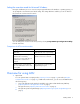
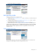
Setting the execution mode for Microsoft Windows During the installation process on a server using a supported Microsoft® Windows® operating system, you are prompted to select the Execution Mode setting. This setting determines whether you can run ACU on the server from a remote network location. You can change the execution mode at any time by selecting Setup HP Array Configuration Utility from the Start menu.
NOTE: Some advanced tasks are not available in all operating modes. For further information, refer to "Tasks possible in each operating mode ("Choosing an operating mode" on page 7)." 2. If you opened ACU in GUI mode: a. Select the controller that you want to configure. b. Select the configuration mode that you want to use ("GUI operating modes" on page 10). 3. Configure the controller.
The browser opens and launches ACU, which then identifies the controllers that are connected to the system. This process could take a minute or two. 2. When controller detection is complete, select a controller from the list on the left side of the screen. The main ACU configuration screen appears. Opening ACU in Browser mode 1. Open ACU on the host. 2.
The main ACU configuration screen appears. Opening ACU through Systems Insight Manager 1. On the server that has ACU loaded, confirm that the utility is running in Remote Service mode ("Setting the execution mode for Microsoft Windows" on page 6). 2. On the remote server, connect to the Systems Insight Manager server (port :280), and log in. 3. Select Device Queries. 4. Under Device by Type, select All Servers. 5. Connect to the server that is running ACU. 6.
The main ACU configuration screen appears. GUI operating modes The GUI format of ACU has three configuration modes: • Standard mode ("Typical Standard mode screen" on page 10) enables you to manually configure all options on the controller. • Configuration Wizards mode ("Typical Configuration Wizards mode screen" on page 11) guides you through each step of a manual configuration process.
Typical Configuration Wizards mode screen The Configuration Wizards mode screen consists of four regions: the Devices list, the Configuration View panel, the Main Menu, and the FAQ column. • The Devices list on the left side of the screen shows all the identifiable controllers that are connected to the system.
Typical Express Configuration mode screen NOTE: Express mode is listed as a configuration option only if the controller that you select has unused space on an array or physical drives that are not assigned to an array. Express Configuration mode screens are similar in appearance to Configuration Wizards mode screens ("Typical Configuration Wizards mode screen" on page 11), but the directive text is different.
Configuring a new controller In this section Using Standard Configuration mode......................................................................................................... 13 Using Express Configuration mode........................................................................................................... 14 Using the configuration wizards...............................................................................................................
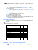
Menu item Possible tasks Array Assign Spare Create Logical Drive Delete Expand Re-Mirror Array Remove Spare Split Mirrored Array More Information Logical drive Delete Extend Size Migrate RAID/Stripe Size Selective Storage Presentation (for RA4x00 controllers) More Information Unused space Create Logical Drive More Information Using Express Configuration mode 1. Click Express Configuration in the lower right panel of the main ACU configuration screen. The Express mode start screen appears. 2.
3. Select a RAID level, and then click Next. 4. If you select a fault-tolerant RAID method and an unassigned physical drive of the appropriate capacity is available, ACU asks if you want to assign spare drives to the array. • If you do not want this array to have a spare, click No, and then click Next. • To assign spares to the array, click Yes, and then click Next. On the next screen, select the drives that you want to be the spares, and then click Next.
The Configuration View panel displays a placeholder for the array that you are about to create. (If there are many physical drives connected to the controller, use the scrollbars in the Configuration View panel to see all the physical drives and arrays.) 3. Select the type of drive that you will use in the array. 4. Select the physical drives that you want to use in the array. • Use physical drives of comparable capacity. ACU uses the same amount of space from each physical drive to build an array.
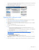
7. Click Finish to confirm the configuration. The drives are now configured as unused space on the new array. To create more arrays on the same controller, repeat the previous steps. Creating a logical drive 1. Click Create a logical drive, and then click Begin. 2. Select an array that has unused space, and then click Next. (The array must have unused space for logical drive creation to be possible.) The screen displays a list of the fault-tolerance levels that are possible for this configuration.
6. Set the size that you want the logical drive to be, and then click Next. If the controller has an array accelerator, a screen appears that gives you the option of disabling it for the currently selected logical drive. NOTE: Disabling the array accelerator for a logical drive reserves use of the accelerator cache for other logical drives on the array.
Modifying an existing configuration In this section Choices available after opening ACU....................................................................................................... 19 Modifying a configuration using Standard Configuration mode ................................................................... 19 Modifying a configuration using Express mode..........................................................................................
Modifying a configuration using Express mode NOTE: Express mode is listed as a configuration option only if the controller that you select has unused space on an array or physical drives that are not assigned to an array. 1. Click Express Configuration, and then click Begin. If there are unassigned physical drives on the controller, you can create a new array or expand an existing array. Make your choice, and then click Next.
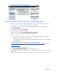
Controller settings The default controller settings that ACU provides are adequate for many purposes. When necessary, however, you can use the Controller Settings task to: • Alter the priority that the system gives to an array expansion or rebuild • Disable the array accelerator (if one is present) • Change the ratio of read cache to write cache (if the controller has battery-backed cache) To change the controller settings: 1. Click Controller Settings, and then click Begin.
• For better system performance, use physical drives that are attached to different ports on the controller. • In RAID 5 configurations, keep the risk of logical drive failure low by assigning no more than 14 physical drives to the array. Each time that you add a physical drive to the array, the configuration view is updated to show how much free space remains on the array. 4. Click Next when you have finished adding physical drives to the array. 5.
The next screen enables you to set the size of the logical drive. The default size shown is the largest possible logical drive size for the RAID level that you chose and the set of physical drives that is being used. Reducing the size of the logical drive liberates drive space, which you can use to build additional logical drives on the same array. 6. Set the size that you want the logical drive to be, and then click Next.
Delete logical drives This task deletes the selected logical drive and converts it into unused drive space. You can then use this unused drive space to: • Create new logical drives ("Create a logical drive" on page 22). • Migrate the RAID level or stripe size of an existing logical drive ("Migrate a logical drive" on page 25). • Extend existing logical drives on the same array ("Extend logical drive" on page 25), if the operating system allows logical drive extension. To delete a logical drive: 1.
To check the progress of an array expansion, click the icon for that array in the Configuration View panel. A More Information pop-up window opens that describes the array status. Extend logical drive This option increases the storage capacity of a logical drive by adding unused space on an array to a logical drive on the same array.
6. Click Finish to accept the changes. At this point (before clicking Save in the next step), you can arrange to migrate another logical drive on the same controller by repeating the previous steps. However, the controller can migrate only one logical drive at a time. Remaining migrations are queued. 7. Click Save. Migration begins. To check the progress of a migration, click the icon for that logical drive in the Configuration View panel.
NOTE: Be sure that every HBA in the system has access to the logical drives for which multi-path will be used. 5. Click Finish. MSA and Smart Array Cluster storage controllers 1. Click Selective Storage Presentation, and then click Begin. On the next screen that appears, select the appropriate radio button to enable or disable SSP, and then click Next. • If you disable SSP, all host controllers have access to all logical drives.
Configuring switches If the selected controller supports switch configuration, the menu link for this feature is given in the Wizards panel in the lower right-hand corner of the main ACU configuration screen. 1. Use the PING command to confirm that the connections between the management server running ACU and the LAN management ports on the switches are reliable. 2. Click Switch Configuration (in the Wizards panel). 3. Select the switch that you want to configure, and then click Next. 4.
The screen now displays a URL for launching the Switch Configuration Utility. This utility is a Java™ applet that enables you to further configure the switch. You might need to load the most current Java™ plug-in to be able to use the applet. 6. Click the URL link. 7. Follow the on-screen prompts and instructions to use the switch configuration utility.
3. Insert the CD that contains ACU into the CD-ROM drive. 4. Open ACU, and stay in Standard configuration mode (the default). 5. Select the controller that contains the array that you want to be re-mirrored. 6. In the Configuration View panel, select the array that you want to use as the source array in the recombined mirrored array. 7. In the Select a Task panel, click Re-Mirror Array. 8. Select the array that is to be mirrored to the source array.
Scripting in ACU In this section Introduction to scripting in ACU ............................................................................................................... 31 Operating modes ................................................................................................................................... 31 Command line syntax ............................................................................................................................. 31 Sample custom input script ....
If you do not specify a capture file name, ACU gives the file the default name of ACUCAPT.INI and places it in the ACU working directory. In Input mode: cpqacuxe -i FILENAME If you do not specify an input file name, ACU gives the file the default name ACUINPUT.INI and places it in the ACU working directory. If any errors occur during either process, these errors are noted in the file ERROR.INI that is logged to the default working directory.
* LogicalDriveSSPState = Enable|Disable * SSPAdaptersWithAccess = [N],[N]...|None HBA_WW_ID = WWN ConnectionName = UserDefinedName HostMode = Default|Windows|Windows(degrade)|openVMS|Tru64|Linux |Solaris|Netware|HP|Windows Sp2 Script file options There are four categories of options in ACU script files: Control, Controller, Array, and Logical Drive. Each category has several scripting options, but you do not always need to assign values to every option.
Category Options Comments Logical drive LogicalDrive These options define a logical drive that is to be configured on an array that is defined previously in the script. (If no array is previously defined, ACU sends an error message.) The LogicalDrive option must be at the beginning of this section of the script, but you can script the other options in this category in any order.
Controller You must enter a value for this option because it identifies the controller that is to be configured. • All—Configure all detected controllers in the system identically. • Slot [N]—Configure the internal controller in slot number N. • WWN [N]—Configure the external controller that has the World Wide Name N. • SerialNumber [N]—Configure the shared storage controller that has serial number N.
Read:write ratio RA4x00 with 16MB cache RA4x00 with 48MB cache All other controllers with battery-backed cache All other controllers without battery-backed cache 70:30 Y Y -- -- 60:40 Y Y -- -- 50:50 Y Y Y -- 40:60 -- Y -- -- 30:70 -- Y -- -- 25:75 -- Y Y -- 0:50* Y -- -- -- 0:75* -- Y -- -- 0:100 -- -- Y -- * The cache ratio percentages do not total 100 in these cases because the additional 16-MB or 48-MB cache modules are not used.
• In Reconfigure mode, ACU can either create a new array or reconfigure an existing array. In this case, the letter value that you specify can identify an existing array, or it can correspond to the next available array letter in the existing configuration. OnlineSpare • • In Automatic mode, the choices are Yes and No. • In Configure mode, the default setting is Yes. • In Reconfigure mode, ACU ignores this option and keeps any spares that the existing configuration already has.
RAID Specify the RAID level that you want for the logical drive. • In Configure mode, the default setting is the highest RAID level that the configuration can support. • In Reconfigure mode, the default setting is the existing RAID level for that logical drive. If you specify a different RAID setting, then ACU either ignores the new setting (in Automatic mode) or attempts to migrate the logical drive to the specified RAID level (in Custom mode).
• For new logical drives, the default value is Disabled. • For existing logical drives, the default value is the current logical drive setting. SSPAdaptersWithAccess Enter values here to identify the SSP adapters that you want to have access to a logical drive. The values are processed only if either SSPState or LogicalDriveSSPState is set to Enable. Otherwise, the values are ignored. NOTE: Be sure that every HBA in the system has access to the logical drives for which multi-path will be used.
ACU scripting error messages Message Comment or explanation (if not self-explanatory) (text) is not a controller command -- (text) is not a logical drive command -- (text) is not a supported command -- (text) is not an array command -- (text) command expected The specified command is missing or in the incorrect place in the file. Array not specified Some commands in the script require an array, but no array is specified in the script file.
Message Comment or explanation (if not self-explanatory) Controller does not support logical drive SSP states. Use the SSPState command to set the controller SSP state. -- Controller does not support redundancy settings The controller is not redundant or does not support redundancy settings.
Message Comment or explanation (if not self-explanatory) Invalid read cache/write cache ratio The specified cache ratio is not supported by either the controller or the current controller configuration. Invalid rebuild priority -- Invalid Sectors The specified Max Boot setting is invalid or is not supported with the current configuration. Invalid Size The specified size is invalid or is not possible with the current configuration.
Using the Command Line Interface In this section Overview of the ACU CLI ........................................................................................................................ 43 Typical procedures ................................................................................................................................. 45 Overview of the ACU CLI The ACU CLI is an interactive command console that provides immediate feedback to the user and is functionally equivalent to the ACU GUI.
The remaining examples in this chapter are described as if entered in Console mode. CLI syntax Whether entered in Command mode or Console mode, a typical ACU CLI command line consists of three parts: a target device, a command, and a parameter with values if necessary.
Keyword Abbreviation in ACU CLI Keyword Abbreviation in ACU CLI chassisname* ch rebuildpriority rp chassisslot chs redundantcontroller rc connectionname cn serialnumber sn controller ctrl stripesize ss drivetype dt surfacescandelay ssd drivewritecache dwc tapedrive td expandpriority ep *The CLI also uses this keyword and abbreviation for the terms box name and RAID array ID.
Creating a logical drive When you use the CLI to create a logical drive, the array that holds the logical drive is created implicitly. (This is different from the GUI procedure, in which the array is created explicitly). Syntax create type=ld [parameter=value] • To create a logical drive on a new array, specify both the controller and the drives that are to constitute the new array.
physicaldrive 1:12 (box 1:bay12, Parallel SCSI, 36.4 GB, OK) unassigned physicaldrive 1:13 (box 1:bay13, Parallel SCSI, 9.1 GB, OK) physicaldrive 1:14 (box 1:bay14, Parallel SCSI, 9.1 GB, OK) The second array is to be created on the two remaining physical drives.
=> ctrl ch="Lab 4" modify ch="Lab 6" Using Selective Storage Presentation SSP (also known as Access Control List commands) enables you to specify which host controllers are to have access to particular logical drives. This feature prevents data corruption that can occur when different servers using different operating systems access the same data. Using SSP requires two commands: • The first command activates the SSP feature on the controller.
=> ctrl ch="Lab 4" MSA1000 at Lab 4 array A logicaldrive array B logicaldrive logicaldrive ld all show 1 (33.
NetWare HP Deleting target devices Syntax: delete [forced] where can be a controller, array, or logical drive. Except in the case of controllers, you can delete several devices simultaneously if they are of similar type by using the all keyword. Because deleting a target device can result in data loss, the screen displays a warning prompt unless you include the forced parameter.
IMPORTANT: An array expansion, logical drive extension, or logical drive migration takes about 15 minutes per gigabyte, or considerably longer if the controller does not have a battery-backed cache. While this process is occurring, no other expansion, extension, or migration can occur simultaneously on the same controller. Syntax: modify size=#|max|? [forced] where is a logical drive.
where is a logical drive. The following limitations apply to this command: • You cannot simultaneously query the RAID level and the stripe size of any given logical drive. • If you do not specify a RAID level for a query or migration, the CLI uses the existing value by default. • If you do not specify a stripe size, the CLI uses the default stripe size value for the RAID level that you specify.
if the controller has a battery-backed cache (because only battery-backed cache can be used for write cache) and if there are logical drives configured on the controller. Syntax: modify cr=#/#|? where is a controller, and #/# is the cache ratio in the format read percentage/write percentage.
Enabling or disabling the array accelerator If the controller has an array accelerator, you can disable it or re-enable it for specified logical drives. NOTE: Disabling the array accelerator for a logical drive reserves use of the accelerator cache for other logical drives on the array. This feature is useful if you want the other logical drives to have the maximum possible performance (for example, if the logical drives contain database information).
array A Interface Type: Parallel SCSI Unused Space: 7949 MB Status: OK Note that the controller does not need to be specified because it is currently the set target. Now clear the target, reset it, and enter a few commands for the new set target: => clear target => set target ctrl slot=3 => array A add drives=1:7,1:8,1:9 => array B add spares=1:10,1:11 => ctrl slot=4 ld 3 modify ss=64 => modify rp=high This sequence includes a command for a different target (the controller in slot 4) as a demonstration.
Probability of logical drive failure In this section Factors involved in logical drive failure ..................................................................................................... 56 Factors involved in logical drive failure The probability that a logical drive will fail depends on the RAID-level setting and on the number and type of physical drives in the array.
Probability of logical drive failure vs.
Drive arrays and fault-tolerance methods In this section Drive arrays........................................................................................................................................... 58 Fault-tolerance methods........................................................................................................................... 60 Drive arrays The capacity and performance of a single physical (hard) drive is adequate for home users.
With an array controller installed in the system, the capacity of several physical drives can be combined into one or more virtual units called logical drives (also called logical volumes and denoted by Ln in the figures in this section). Then, the read/write heads of all the constituent physical drives are active simultaneously, reducing the total time required for data transfer.
logical drive, the term array is often used as a synonym for logical drive. However, an array can contain several logical drives, each of a different size. Each logical drive in an array is distributed across all of the physical drives within the array. A logical drive can also extend across more than one port on the same controller, but it cannot extend across more than one controller. Drive failure, although rare, is potentially catastrophic.
• RAID 1+0—Drive Mirroring • RAID 5—Distributed Data Guarding • RAID 6 (ADG)—Advanced Data Guarding RAID 0—No fault tolerance A RAID 0 configuration provides data striping, but there is no protection against data loss when a drive fails. However, it is useful for rapid storage of large amounts of noncritical data (for printing or image editing, for example) or when cost is the most important consideration. Advantages: • Has the highest write performance of all RAID methods.
RAID 1+0—drive mirroring In a RAID 1+0 configuration, data is duplicated to a second drive. When the array has more than two physical drives, drives are mirrored in pairs. In each mirrored pair, the physical drive that is not busy answering other requests answers any read requests that are sent to the array. (This behavior is called load balancing.) If a physical drive fails, the remaining drive in the mirrored pair can still provide all the necessary data.
• No data is lost when a drive fails, as long as no failed drive is mirrored to another failed drive (up to half of the physical drives in the array can fail). Disadvantages: • This method is expensive (many drives are needed for fault tolerance). • Only half of the total drive capacity is usable for data storage. RAID 5—distributed data guarding In a RAID 5 configuration, data protection is provided by parity data (denoted by Px,y in the figure).
and Qx,y in the figure), allowing data to still be preserved if two drives fail. Each set of parity data uses a capacity equivalent to that of one of the constituent drives. This method is most useful when data loss is unacceptable but cost is also an important factor. The probability that data loss will occur when an array is configured with RAID 6 (ADG) is less than it would be if it was configured with RAID 5. Advantages: • This method has a high read performance.
Item RAID 0 RAID 1+0 RAID 5 RAID 6 (ADG) Tolerates simultaneous failure of more than one physical drive No Only if no two failed drives are in the same mirrored pair No Yes Read performance High High High High Write performance High Medium Low Low Relative cost Low High Medium Medium *Values for the fraction of drive space usable are calculated with these assumptions: (1) all physical drives in the array have the same capacity; (2) online spares are not used; (3) no more than 14 phy
Diagnosing array problems In this section Diagnostic tools ..................................................................................................................................... 66 Diagnostic tools Several diagnostic tools provide feedback about problems with arrays. The most important are: • ADU This utility is available on the SmartStart CD. The meanings of the various ADU error messages are provided in the HP Servers Troubleshooting Guide.
Acronyms and abbreviations ACR Array Configuration Replicator ADG Advanced Data Guarding (also known as RAID 6) ADU Array Diagnostics Utility CLI Command Line Interface GUI graphical user interface HBA host bus adapter MSA Modular Smart Array MTBF mean time between failures POST Power-On Self Test PSP ProLiant Support Pack RAID redundant array of inexpensive (or independent) disks SA Smart Array Acronyms and abbreviations 67
SSP Selective Storage Presentation WBEM Web-Based Enterprise Management WWN World Wide Name Acronyms and abbreviations 68
Index extending logical drive capacity 25, 38 A ADU (Array Diagnostic Utility) 66 array accelerator, disabling 17, 21, 54 array capacity expansion 24 array concepts 58 array configuration, copying 31 array expansion, setting priority of 21 array, creating 14, 15 B browser mode 8 C cache ratio, setting 21, 35 clear a configuration 20 CLI (Command Line Interface) 43 configuration modes 10 configuring an array 15, 21 connection name 39, 49 controller duplexing 65 D data protection methods 60, 65 default se
RAID levels 60, 61, 62, 63 RAID levels, comparison of features 64 RAID, software-based 65 read-write ratio, setting 21 rebuild priority 21 recombining a split array 29 redundant controller, disabling 54 re-enabling a failed logical drive 53 Remote Service mode 6 replication of array configuration 31 resolution of monitor 5 S sample script 32 screen resolution 5 scripting syntax 31 Selective Storage Presentation 26 Server Diagnostics utility 66 software-based RAID 65 spare drives 14, 15, 26, 51 splitting an