HP Smart Array P800 Controller for HP Integrity Servers User Guide Part Number 432599-003 August 2007 (Third Edition)
© Copyright 2006, 2007 Hewlett-Packard Development Company, L.P. The information contained herein is subject to change without notice. The only warranties for HP products and services are set forth in the express warranty statements accompanying such products and services. Nothing herein should be construed as constituting an additional warranty. HP shall not be liable for technical or editorial errors or omissions contained herein. Microsoft and Windows are U.S.
Contents Hardware features ........................................................................................................................ 5 Main components on the board .................................................................................................................. 5 Controller specifications ............................................................................................................................. 5 Overview of the installation procedure .....................
Diagnosing array problems.......................................................................................................... 34 Controller board runtime LEDs................................................................................................................... 34 Battery pack LEDs.................................................................................................................................... 35 Diagnostic tools ...........................................................
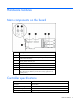
Hardware features Main components on the board Item ID Description 1 Connector for SAS miniports 1E and 2E (external), each 4x wide 2 Heartbeat LED (flashes green when operating normally and amber if the board has failed) 3 Activity LED for external ports 4 SAS port 3I (internal), 4x wide 5 SAS port 4I (internal), 4x wide 6 Cache module (also known as BBWC or array accelerator) 7 Batteries for cache module (Two batteries are normally sufficient, but a third can be added to provide extra secu
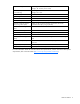
Temperature range Operating, 10° to 55°C (50° to 131°F) Storage, -30° to 60°C (-22° to 140°F) Relative humidity (noncondensing) Operating, 10% to 90% Storage, 5% to 90% RAID levels supported 0, 1, 1+0, and 5; also 6 if the batteries are used Type of edge connector PCIe x8 PCIe transfer rate Up to 2 GB/s in each direction Number of SAS ports Two internal, two external; each port has four 1x links Maximum number of physical drives (using all four ports) 108 (8 can be connected internally, and a f
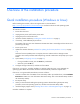
Overview of the installation procedure Quick installation procedure (Windows or Linux) Before installing the controller, refer to the support matrix on the HP website (http://www.hp.com/products1/serverconnectivity) to confirm that the server and operating system support the controller. To install the controller: 1. Power down the server. 2. Unplug the AC power cord from the power outlet. 3. Unplug the power cord from the server. 4.
The latest firmware, drivers, utilities, software, and documentation for HP Integrity servers are available on the support page of the HP website (http://www.hp.com/support/itaniumservers).
Installing the controller hardware Preparing the server 1. Back up all data. 2. Close all applications. 3. Power down the server. CAUTION: In systems that use external data storage, be sure that the server is the first unit to be powered down and the last to be powered back up. Taking this precaution ensures that the system does not erroneously mark the drives as failed when the server is powered up. 4. Power down all peripheral devices that are attached to the server. 5.
CAUTION: Do not operate the server for long periods with the access panel open or removed. Operating the server in this manner results in improper airflow and improper cooling that can lead to thermal damage. Connecting storage devices You can connect SAS or SATA drives to the controller internally ("Connecting internal storage" on page 10) or externally ("Connecting external storage" on page 10). For information about supported drive models, see the controller-specific page on the HP website (http://www.
o If the enclosure uses a mini SAS 4x connector, pull back the tab on the cable connector, insert the cable connector into the enclosure connector, and then release the tab. 4. Power up the enclosure. 5. Power up the server. SAS cable part numbers To order additional cables, use the option kit part number.
Updating the firmware Methods for updating the firmware (Windows or Linux) To update the firmware on the server, controller, or hard drives, use Smart Components. The most recent version of a particular component is available on the support page of the HP website (http://www.hp.com/support). Some components are also available on the Smart Setup media. 1. Find the most recent version of the component that you require. 2. Follow the instructions for installing the component on the server.
Configuring an array Utilities available for configuring an array Two utilities are available for configuring an array on an HP Smart Array controller in an HP Integrity server: ORCA and ACU. • ORCA is a simple utility that is used mainly to configure the first logical drive in a new server before the operating system is loaded. • ACU is an advanced utility that enables you to perform many complex configuration tasks.
Supported procedures ACU ORCA Assignment of RAID level + + Sharing of spare drives among several arrays + -- Assignment of multiple spare drives per array + -- Setting of stripe size + -- Migration of RAID level or stripe size + -- Configuration of controller settings + -- Expansion of an array + -- Creation of multiple logical drives per array + -- Using ORCA 1. Power up the server. POST runs, and any array controllers that are in the server are initialized one at a time.
You can now create another logical drive by repeating the previous steps. NOTE: Newly created logical drives are invisible to the operating system. To make the new logical drives available for data storage, format them using the instructions given in the operating system documentation. Using ACU For detailed information about using ACU, see the Configuring Arrays on HP Smart Array Controllers Reference Guide.
Installing device drivers and Management Agents Systems using Microsoft Windows You can use the Integrity Support Pack to automatically install the device drivers, Event Notification Service, and Management Agents, or you can install these items manually. The Integrity Support Pack is located on the Smart Setup media. To install the Integrity Support Pack, launch Express Setup from EBSU and follow the on-screen instructions.
3. Follow the standard procedure for installing Linux. As Linux is installed, it recognizes the controller and automatically loads the correct driver. In a system that already has Linux installed: 1. Power down the system. 2. Follow the standard controller installation procedure. 3. Power up the system. As Linux boots, it recognizes the controller. 4.
Upgrading or replacing controller options Replacing or adding a battery CAUTION: Electrostatic discharge can damage electronic components. Be sure you are properly grounded before beginning this procedure. For more information, see "Electrostatic Discharge (on page 38)." 1. Close all applications, and then power down the server. This procedure flushes all data from the cache. 2. Observe the BBWC Status LED ("Battery pack LEDs" on page 35).
6. While holding the battery assembly, tilt the clip until it is at about 30 degrees to the batteries, and then push the clip in line with the clip hinges until the clip detaches from the batteries. The rest of the procedure depends on whether you are replacing a battery or adding one. 7. o If you are replacing a battery, continue with the next step. o If you are only adding an optional third battery, go to step 9. Separate the batteries. a. Turn the batteries over. b.
9. Position the new battery and the remaining good battery as indicated, and then push them together and slide them until they are aligned. The batteries combine into one unit. 10. Install the battery clip. a. Position the clip so that the hinges on the clip are next to the appropriate hinge pillars on the batteries. b. Hold the clip at about 30 degrees to the batteries. c. 11. Push the clip at the hinges until the clip clicks into place. Reinstall the batteries. a.
b. Position the batteries so that the pegs A on the underside of each battery are in the appropriate holes B on the controller board and pegs C are in slots D. c. 12. Slide the batteries toward the board bracket until they are firmly seated against the connectors on the cache module. Secure the battery clip to the controller board: a. Swivel the clip over the cache module (1).
b. Push the clip firmly at both ends (2) until it clicks into place under the controller board. 13. Reinstall the controller in the server. After installing a battery pack, you might see a POST message during reboot indicating that the array accelerator (cache) is temporarily disabled. This behavior is normal because the new battery pack is likely to have a low charge. You do not need to take any action because the recharge process begins automatically when the battery pack is installed.
4. Pull the flanges on the battery clip outward (1), and then swivel the clip 180 degrees so that it rests on the batteries (2). 5. Swivel the latches on the DIMM connector outward (1). 6. Slide the battery assembly and the cache module off the controller board (2). The procedure at this point depends on whether you are replacing the controller or the cache module. 7. o If you are replacing the controller, go directly to the next step.
b. Position the batteries so that the pegs A on the underside of each battery are in the appropriate holes B on the controller board and pegs C are in slots D. c. 8. Slide the batteries toward the board bracket until the connectors on the cache module are firmly seated in the DIMM connector. (When the cache module is correctly seated, the gold contacts on the cache module are completely hidden within the DIMM connector.) Secure the battery clip to the controller board. a.
b. Push the clip firmly at both ends (2) until it clicks into place under the controller board. 9. Reinstall the controller in the server.
Replacing, moving, or adding hard drives Identifying the status of a hard drive When a drive is configured as a part of an array and connected to a powered-up controller, the condition of the drive can be determined from the illumination pattern of the hard drive status lights (LEDs).
Online/activity LED (green) Fault/UID LED (amber/blue) Interpretation Flashing regularly (1 Hz) Amber, flashing regularly (1 Hz) Do not remove the drive. Removing a drive may terminate the current operation and cause data loss. The drive is part of an array that is undergoing capacity expansion or stripe migration, but a predictive failure alert has been received for this drive. To minimize the risk of data loss, do not replace the drive until the expansion or migration is complete.
Effects of a hard drive failure When a hard drive fails, all logical drives that are in the same array are affected. Each logical drive in an array might be using a different fault-tolerance method, so each logical drive can be affected differently. • RAID 0 configurations cannot tolerate drive failure. If any physical drive in the array fails, all nonfault-tolerant (RAID 0) logical drives in the same array will also fail.
Replacing hard drives The most common reason for replacing a hard drive is that it has failed. However, another reason is to gradually increase the storage capacity of the entire system. If you insert a hot-pluggable drive into a drive bay while the system power is on, all disk activity in the array pauses for a second or two while the new drive is spinning up.
Automatic data recovery (rebuild) When you replace a hard drive in an array, the controller uses the fault-tolerance information on the remaining drives in the array to reconstruct the missing data (the data that was originally on the replaced drive) and write it to the replacement drive. This process is called automatic data recovery, or rebuild. If fault tolerance is compromised, this data cannot be reconstructed and is likely to be permanently lost.
Observation Cause of rebuild termination None of the drives in the array have an illuminated amber Fault LED. One of the drives in the array has experienced an uncorrectable read error. The replacement drive has an illuminated amber Fault LED. The replacement drive has failed. One of the other drives in the array has an illuminated amber Fault LED. The drive with the illuminated Fault LED has now failed. Each of these situations requires a different remedial action.
Upgrading hard drive capacity You can increase the storage capacity on a system even if there are no available drive bays by swapping drives one at a time for higher capacity drives. This method is viable as long as a fault-tolerance method is running. CAUTION: Because it can take up to 15 minutes per gigabyte to rebuild the data in the new configuration, the system is unprotected against drive failure for many hours while a given drive is upgraded.
4. Power up the system. If a 1724 POST message appears, drive positions were changed successfully and the configuration was updated. If a 1785 (Not Configured) POST message appears: a. Power down the system immediately to prevent data loss. b. Return the drives to their original locations. c. 5. Restore the data from backup, if necessary. Verify the new drive configuration by running ORCA or ACU ("Configuring an array" on page 13).
Diagnosing array problems Controller board runtime LEDs Immediately after the server is powered up, the controller runtime LEDs illuminate briefly in a predetermined pattern as part of the POST sequence. At all other times during server operation, the illumination pattern of the runtime LEDs indicates the status of the controller, as described in the following table. LED ID Color LED name and interpretation 1 Green CR502: Expander Heartbeat LED.
LED ID Color LED name and interpretation 9 Green CR504: Gas Pedal LED. This LED, together with item 10, indicates the amount of controller CPU activity. For details, see the following table. 10 Green CR503: Idle Task LED. This LED, together with item 9, indicates the amount of controller CPU activity. For details, see the following table.
LED3 pattern LED4 pattern Interpretation — One blink every two seconds The system is powered down, and the cache contains data that has not yet been written to the drives. Restore system power as soon as possible to prevent data loss. Data preservation time is extended any time that 3.3 V auxiliary power is available, as indicated by LED 2. In the absence of auxiliary power, battery power alone preserves the data. A fullycharged battery can normally preserve data for at least two days.
Smart Array controllers produce diagnostic error messages at reboot. Many of these POST messages are self-explanatory and suggest corrective actions. For more information about POST messages, refer to the HP Servers Troubleshooting Guide.
Electrostatic discharge Preventing electrostatic discharge To prevent damaging the system, be aware of the precautions you need to follow when setting up the system or handling parts. A discharge of static electricity from a finger or other conductor may damage system boards or other static-sensitive devices. This type of damage may reduce the life expectancy of the device. To prevent electrostatic damage: • Avoid hand contact by transporting and storing products in static-safe containers.
Regulatory compliance notices Federal Communications Commission notice This equipment has been tested and found to comply with the limits for a Class A digital device, pursuant to Part 15 of the FCC Rules. These limits are designed to provide reasonable protection against harmful interference when the equipment is operated in a commercial environment.
This marking is valid for non-Telecom products and EU harmonized Telecom products (e.g. Bluetooth). This marking is valid for EU non-harmonized Telecom products. *Notified body number (used only if applicable—refer to the product label) Hewlett-Packard GmbH, HQ-TRE, Herrenberger Strasse 140, 71034 Boeblingen, Germany BSMI notice Japanese class A notice Korean class A notice Battery replacement notice This component uses a nickel metal hydride (NiMH) battery pack.
WARNING: There is a risk of explosion, fire, or personal injury if a battery pack is mishandled. To reduce this risk: • Do not attempt to recharge the batteries if they are disconnected from the controller. • Do not expose the battery pack to water, or to temperatures higher than 60°C (140°F). • Do not abuse, disassemble, crush, or puncture the battery pack. • Do not short the external contacts. • Replace the battery pack only with the designated HP spare.
Acronyms and abbreviations ACU Array Configuration Utility ADG Advanced Data Guarding (also known as RAID 6) ADU Array Diagnostics Utility BBWC battery-backed write cache DIMM dual inline memory module EBSU EFI-based setup utility EFI extensible firmware interface LED light-emitting diode ORCA Option ROM Configuration for Arrays PCIe peripheral component interconnect express POST Power-On Self Test Acronyms and abbreviations 42
Index A ACU (Array Configuration Utility) 13, 15 adding drives 33 ADU (Array Diagnostic Utility) 36 Array Configuration Utility (ACU) 13, 15 array controller installation overview 7 Array Diagnostic Utility (ADU) 36 array expansion 33 array, configuring 13 array, moving 32 automatic data recovery (rebuild) 30 B batteries, replacing 18 batteries, specifications 5 battery pack LEDs 35 battery replacement notice 40 board components 5 BSMI notice 40 C cable part numbers 11 cables 39 cache, features 5 cache, r
J S Japanese notice 40 spares, battery pack, part number 5 spares, cable part numbers 11 specifications, controller 5 static electricity 38 status lights, battery pack 35 status lights, controller 34 status lights, hard drive 26 storage capacity, increasing 32 storage devices, connecting 10 summary of installation procedure 7 K Korean notices 40 L LEDs, battery pack 35 LEDs, controller 34 LEDs, hard drive 26 logical drive capacity extension 33 logical drive, creating 13 logical drives, maximum number o