installation guide hp StorageWorks host bus adapter for Windows and Linux Third Edition (April 2003) Part Number: AA–RTD1C–TE This guide describes how to install, configure, and use the diagnostic utilities for the HP StorageWorks A7298A host bus adapter for Windows Server 2003 and Linux platforms.
© Hewlett-Packard Company, 2003. All rights reserved. Hewlett-Packard Company makes no warranty of any kind with regard to this material, including, but not limited to, the implied warranties of merchantability and fitness for a particular purpose. Hewlett-Packard shall not be liable for errors contained herein or for incidental or consequential damages in connection with the furnishing, performance, or use of this material. This document contains proprietary information, which is protected by copyright.
contents Contents About this Guide. . . . . . . . . . . . . . . . . . . . . . . . . . . . . . . . . . . . . . . . . . . . . . . . . . . .7 Overview. . . . . . . . . . . . . . . . . . . . . . . . . . . . . . . . . . . . . . . . . . . . . . . . . . . . . . . . . . . . . . . . . . 8 Intended Audience . . . . . . . . . . . . . . . . . . . . . . . . . . . . . . . . . . . . . . . . . . . . . . . . . . . . . . . 8 Related Documentation . . . . . . . . . . . . . . . . . . . . . . . . . . . . . . . . . . . . . . .
Contents 3 Installing the SCSI Miniport Driver . . . . . . . . . . . . . . . . . . . . . . . . . . . . . . . . . . . . . .31 Introduction. . . . . . . . . . . . . . . . . . . . . . . . . . . . . . . . . . . . . . . . . . . . . . . . . . . . . . . . . . . . . . . 31 Windows Server 2003 Device Driver Installation . . . . . . . . . . . . . . . . . . . . . . . . . . . . . . . . . 32 Windows Server 2003 System Requirements . . . . . . . . . . . . . . . . . . . . . . . . . . . . . . . . .
Contents Test Host Bus Adapters (For lputilnt Only). . . . . . . . . . . . . . . . . . . . . . . . . . . . . . . . . . . Modify Test Options (For lputilnt Only) . . . . . . . . . . . . . . . . . . . . . . . . . . . . . . . . . . . . . Reset Host Bus Adapters . . . . . . . . . . . . . . . . . . . . . . . . . . . . . . . . . . . . . . . . . . . . . . . . . Input/Output . . . . . . . . . . . . . . . . . . . . . . . . . . . . . . . . . . . . . . . . . . . . . . . . . . . . . . . . . . .
Contents 6 Host Bus Adapter for Windows and Linux Installation Guide
about this guide About this Guide This installation guide provides information to help you: ■ Install, configure, and About use the utilities for the HP StorageWorks this diagnostic Guide A7298A host bus adapter for Windows and Linux platforms. ■ Contact technical support for additional assistance.
About this Guide Overview This section covers the following topics: ■ Intended Audience ■ Related Documentation Intended Audience This book is intended for use by system administrators who are experienced with the following: ■ Windows Server 2003 ■ Linux Red Hat Advanced Workstation v2.
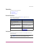
About this Guide Conventions Conventions consist of the following: ■ Document Conventions ■ Text Symbols ■ Equipment Symbols Document Conventions The document conventions included in Table 1 apply in most cases.
About this Guide Caution: Text set off in this manner indicates that failure to follow directions could result in damage to equipment or data. Note: Text set off in this manner presents commentary, sidelights, or interesting points of information. Equipment Symbols The following equipment symbols may be found on hardware for which this guide pertains. They have the following meanings.
About this Guide Power supplies or systems marked with these symbols indicate the presence of multiple sources of power. WARNING: To reduce the risk of personal safety from electrical shock, remove all power cords to completely disconnect power from the power supplies and systems. Any product or assembly marked with these symbols indicates that the component exceeds the recommended weight for one individual to handle safely.
About this Guide Rack Stability Rack stability protects personnel and equipment. WARNING: To reduce the risk of personal safety or damage to the equipment, be sure that: ■ The leveling jacks are extended to the floor. ■ The full weight of the rack rests on the leveling jacks. ■ In single rack installations, the stabilizing feet are attached to the rack. ■ In multiple rack installations, the racks are coupled. ■ Only one rack component is extended at any time.
About this Guide Getting Help If you still have a question after reading this guide, contact an HP authorized service provider or access our website: http://www.hp.com. HP Technical Support Telephone numbers for worldwide technical support are listed on the following HP website: http://www.hp.com/support/. From this website, select the country of origin. Note: For continuous quality improvement, calls may be recorded or monitored.
About this Guide 14 Host Bus Adapter for Windows and Linux Installation Guide
1 Introduction 1 This user guide provides information to help you install, configure, and use the diagnostic utilities for the HP StorageWorks A7298A host bus adapter for Windows and Linux platforms.
Introduction Product Description The HBA has the following characteristics: 16 ■ Robust suite of software supporting Windows Server 2003 and Linux Red Hat Advanced Workstation v2.1. ■ Optical small form factor (LC) interface LC Fibre connector. ■ Embedded optical short-wave laser, multi-mode Fibre Channel interface. ■ Designed using a single custom Application Specific Integrated Circuit (ASIC).
Introduction Figure 1: Host Bus Adapter Table 2: Host Bus Adapter Diagram Description Figure Legend Description 1 Fibre Channel (LC) connectors. 2 POST LEDs indicators Note: See Table 3 and Table 4 for detailed descriptions.
Introduction Performance Specifications The PCI-X host bus adapter offers a highly integrated 2Gbps Fibre Channel HBA for use in servers based on either PCI or the latest PCI-X expansion bus. The features of this PCI-X based HBA provide the flexibility and broad interoperability needed for complex, highly scalable SANs. The HBA also features sophisticated hardware that provides superior performance in SANs and provides best in class server CPU offload.
Introduction Boot BIOS Specifications Boot BIOS is a set of x86 instructions in the Host Bus Adapter (HBA) flash ROM that lets you designate a Fibre Channel attached drive as the boot drive. Boot BIOS works with the existing system BIOS on Intel Pentium class PCI system boards. Boot BIOS supports: ■ Multiple topologies: Fabric Point-to-Point and FC-AL Private Loop ■ Multiple boot compliance ■ Supports Enhanced Disk Driver Services (EDD) Version 3.
Introduction Standards The HBA conforms to the following standards: 20 ■ ANSI Fibre Channel FC-PH, Revision 4.3 ■ ANSI Fibre Channel FC-AL, Revision 4.5 ■ PCI Local Bus, Revisions 2.1 and 2.
Introduction Agency Approvals The HBA has the following agency approvals: ■ CFR Title 21, Laser AEL Class 1, FDA/CDRH ■ UL recognized to UL1950 ■ CUR recognized to CSA22.2, No.
Introduction 22 Host Bus Adapter for Windows and Linux Installation Guide
2 Installation 2 Installation Overview This chapter provides step-by-step instructions for installing the HP StorageWorks A7298A Host Bus Adapter (HBA) including: ■ Hardware Requirements ■ Recording Reference Numbers ■ Installing the HBA into a Computer ■ Verifying the Installation ■ Configuration Guidelines This chapter also provides information on installation guidelines and supported configurations for the operating systems. IMPORTANT: The HBA contains static-sensitive components.
Installation Hardware Requirements The system hardware requirements for installing the HBA include: 24 ■ A host computer that provides 3.3VDC PCI and PCI-X bus power ■ One open 64-bit 33/66 MHz PCI or 66/100/133 MHz PCI-X bus slot with either a 3.3 or a 5.
Installation Recording Reference Numbers Each HBA ships with a unique address identifier that is stored in flash memory. Fibre Channel industry standards issue two unique identifiers: WorldWide Port Name (WWPN) and Node Name (NN), each of which is derived from the HBA’s IEEE address. Combined, the WWPN and NN create the WorldWide Name (WWN) which is an 8-byte field that uniquely identifies an HBA on a FC circuit. The WWN address and serial number are clearly marked on the HBA.
Installation Installing the HBA into a Computer Following is the procedure for installing the HBA into a computer. WARNING: Be sure to observe the ESD precautions for this procedure. 1. Make sure the computer is powered off. 2. Remove the screws on the computer cover, and then remove the cover. 3. Wearing a static wrist strap, remove the blank panel from an empty 64-bit PCI or PCI-X bus slot. Compare the removed panel to the bracket on the host bus adapter.
Installation 11. Attach media: a. Connect the fiber optic cable to the LC connector on the HBA. b. Connect the other end of the cable to the Fibre Channel device. Note: The HBA does not allow normal data transmission on an optical link unless it is connected to a similar or compatible laser product. That is, both products are multimode to multimode.
Installation Verifying the Installation To verify the HBA is properly installed and is operating: 1. Turn on the computer. 2. At power up, observe the POST LED indicators on the HBA. The position of the POST LED indicators is defined in Figure 1 and Table 2 of this guide. The green LED indicates power functions and the amber LED signifies port activity. The amber LED blinks at all times during normal operation. Table 3 lists normal LED indications.
Installation Configuration Guidelines The software for loading the driver also contains the default registry parameter settings that are loaded as part of the driver installation. Consult the following sources for any restriction and for information on supported configurations specific to your operating system and topology. ■ Release Notes ■ HP Website at: http://www.hp.com/support/itaniumservers.
Installation 30 Host Bus Adapter for Windows and Linux Installation Guide
Installing the SCSI Miniport Driver 3 3 Introduction This chapter contains step-by-step instructions for installing the Windows Server 2003 and Linux SCSI Miniport drivers. System managers must be familiar with the operating system under which the PCI or PCI-X-to-Fibre Channel Host Bus Adapter (HBA) is to operate. System managers must also have access to standard system documentation.
Installing the SCSI Miniport Driver Windows Server 2003 Device Driver Installation This section describes the instructions for installing the Windows Server 2003 SCSI Miniport driver. Windows Server 2003 System Requirements Ensure that your system meets these minimum requirements: ■ Installed HBA ■ Ensure the HP Setup and Configuration CD for Itanium(R) 2-based servers is in the server or the driver has been downloaded from the web and copied to the server hard drive.
Installing the SCSI Miniport Driver d. Verify that the SCSI Miniport driver is present and started. Removing the Windows Server 2003 SCSI Device Driver To remove the device driver from the Windows Server 2003 desktop: 1. Click Start > Settings > Control Panel. 2. Double-click the System icon. 3. Click Device Manager. 4. Open the SCSI and RAID controllers item in the list. 5. Click Remove. 6. Choose Yes to confirm. 7. Click OK. 8. Reboot the computer to restart Windows Server 2003.
Installing the SCSI Miniport Driver Linux Device Driver Installation This section describes the instructions for installing the Linux SCSI Miniport driver.
Installing the SCSI Miniport Driver Installing the Linux Driver Using a Tar File To install the driver and boot the system, you must be running as root. 1. Enter the following command to create a temporary directory (for example, emlxtemp). # mkdir emlxtemp 2. Enter the following command to change directory to the temporary directory. # cd emlxtemp 3. Copy or download the device driver file to the temporary directory. 4. Enter the following command if the file is in the format filename.rpm.
Installing the SCSI Miniport Driver Installing the Linux Driver Using an RPM File To install the driver and boot the system, you must be running as root. 1. Enter the following command to create a temporary directory (for example, emlxtemp). # mkdir emlxtemp 2. Enter the following command to change directory to the temporary directory. # cd emlxtemp 3. Copy or download the device driver RPM file to the temporary directory. 4. Enter the following command if the file is in the format filename.rpm.
Installing the SCSI Miniport Driver Building the Driver as a Module Once you have installed the source file, you can build the driver as a module. 1. At the shell prompt, edit lpfc.conf.c to reflect your desired configuration. 2. Enter the following command to verify that both kernel-headers and kernel-source RPMs are installed: # rpm -a -q | grep kernel 3.
Installing the SCSI Miniport Driver The edited text should now display as follows: # For 32-bit # If this is CFLAGSCFLAGS $[MODINC] environment not a SMP environment remove the -D__SMP__=1 from = -D__KERNEL__=1 \ $[INCLUDEDIR] 7. For SuSE Linux, enter the following ifconfig command (all on one line): # cp /boot/vmlinuz.version.h /lib/modules/'uname-r'/build/include/linux/version.h 8.
Installing the SCSI Miniport Driver Loading the Driver There are two ways to load the driver: manually or through the RAM disk image. Loading the Driver Manually 1. Enter the following commands: # insmod lpfcdd # insmod lpfndd lpfcdd - main driver, SCSI functionality, FCP support, diagnostic support lpfndd - IP support (this driver is dependent on lpfcdd being loaded first) 2. Enter the following command to bring up the interface: Edit /etc/sysconfig/network-scripts/ifcfg-lpfnX. 3.
Installing the SCSI Miniport Driver Loading the Driver Through the RAM Disk Image 1. To add SCSI and IP modules, edit /etc/conf.modules or modules.conf, depending on the Linux release. Add the following line to add a SCSI module: alias scsi_hostadapter lpfcdd Add the following line to add an IP module: alias lpfnX lpfndd where X is the interface number, 0 through 7. Note: If you want to configure SCSI only, just add the scsi_hostadapter line.
Installing the SCSI Miniport Driver timeout=50 default=linux image=/boot/vmlinuz-kernel_version label=linux root=/dev/sda8 initrd=/boot/initrd-kernel_version.imgread-only 4. Add the following lines to the end of the file to add a new boot record for the driver: image=/boot/vmlinuz-kernel_version label=new_label root=/dev/sda8 initrd=/boot/new_image_filenameread-only append=”max_scsi_luns=128” Note: Currently, lpfc is not supported as the root device, so keep the “root=/dev/xxx” parameter the same. 5.
Installing the SCSI Miniport Driver Building the Driver Into the Kernel SCSI Functionality Once you have installed the source files, you can build the driver into the kernel. 1. Enter the following commands: # # # # mkdir /usr/src/linus/scsi/lpfc find . -print | cpio -pdumv /usr/src/linux/drivers/scsi/lpfc cd /usr/src/linux/drivers/scsi/lpfc cp Makefile.kernel Makefile 2. Edit the Makefile and the lpfc.conf.c files, if needed. 3.
Installing the SCSI Miniport Driver The edited lines should now display as follows: subdir-$(CONFIG_IDE) += ide subdir-$(CONFIG_SCSI_LPFC) += scsi/lpfc subdir-$(CONFIG_SCSI) += scsi 8. Go to the scsi directory: # cd /usr/src/linux/drivers/scsi Edit Config.in and locate the following lines (the lines may wrap.): dep_tristate 'EATA-PIO [old DPT PM2001, PM2012A] support' CONFIG_SCSI_EATA_PIO $CONFIG_SCSI dep_tristate 'Future Domain 16xx sCSI/AHA-2920A support' CONFIG_SCSI_FUTURE_DOMAIN $CONFIG_SCSI 9.
Installing the SCSI Miniport Driver 14. At the end of the definition for Scsi_Host_Template, before “Removable host adapters”, add the following lines: #ifdef CONFIG_SCSI_LPFC EMULEXFC, #endif IP Functionality 1. Go to the net directory: # cd /usr/src/linux/drivers/net 2. Edit Config.in.
Installing the SCSI Miniport Driver 5.
Installing the SCSI Miniport Driver “fc1”, 0, 0, 0, 0, 0, 0, 0, 0, 0, NEXT_DEV, fcif_probe}; static struct net_device fc0_dev = { “fc0”, 0, 0, 0, 0, 0, 0, 0, 0, 0, &fc1_dev, fcif_probe}; # undef NEXT_DEV # define NEXT_DEV (&fc0_dev)static struct net_device lpfn_dev = { “lpfn”, 0, 0, 0, 0, 0, 0, 0, 0, 0, NEXT_DEV, lpfnif_probe}; # undef NEXT_DEV # define NEXT_DEV (&lpfn_dev) #endif 8.
Installing the SCSI Miniport Driver Setting up and Running Diagnostic Utilities 1. Go to the driver source directory. # cd driver_installation_directory 2. Enter one of the following commands to run the diagnostic utilities: # ./lputil or # ./dfc Installing the Latest Version of HBA API and Utilities 1. Enter the following command to install the latest version of HBA API and utilities: # sh Install.
Installing the SCSI Miniport Driver 48 Host Bus Adapter for Windows and Linux Installation Guide
4 Troubleshooting 4 Introduction The Power-On Self Test (POST) and the Windows Event Viewer are troubleshooting utilities you can use for the Host Bus Adapter (HBA). This chapter explains the use of these utilities in the event of an HBA problem.
Troubleshooting POST Conditions and Results Table 4 lists the HBA LED states with descriptions of each.The position of the POST LED indicators is defined in Figure 1 and Table 2 of this guide. If the LEDs indicate a failure during POST: 1. Make sure that the HBA is seated firmly in the PCI slot. 2. Verify that the fibre cable connection to the HBA is secure.
Troubleshooting Using The Event Viewer The Windows SCSI driver verifies the condition of the HBA POST. If there is a failure or a suspected failure, an error log entry is issued to the Windows Event log. Following is the procedure for viewing the event log. From the Main menu: 1. Double-click or choose the Administrative Tools program group. 2. Double-click or choose the Event Viewer.
Troubleshooting Windows Miniport Event Log Codes The Windows Miniport driver logs events and errors in the Windows Event log. Serious errors are always logged. Informational events are only logged if the registry parameter LogError=1 is used. All Miniport logged events are issued with an Event ID of 11 (INTERNAL ADAPTER ERROR) but do not necessarily indicate an HBA error occurred. Byte offset 0x10 of the event is the driver event code. Byte offsets 0x11 to 0x13 contain event-specific information.
Troubleshooting Table 5: SCSI Port Error Log Codes (Continued) 0x10 Offset Explanation 0x11 to 0x13 Further Information 0xE2 Mailbox cmd time-out 0x11 = command 0xE3 Mailbox rsp err 0x11 = command, 12-13 = mbxstatus 0xE4 HBA not ready after init Status register bytes 1-3 in event 11-13 0xE5 Requested loop but link = PT-PT 0xE6 Mailbox int.
Troubleshooting Table 5: SCSI Port Error Log Codes (Continued) 0x10 Offset Explanation 0x11 to 0x13 Further Information 0xF6 PCP_IXXX_CR IOCB rsp err 0x11 = cmdstat, 12 = parm err, 13 = ALPA 0xF7 Ring hd !=0 && pendingsrb!=NULL 0xF8 Invalid FCP_RSP 0xF9 Two consec.
Troubleshooting Table 7: Parameter Error Values Valid only when CmdStat=0x3 0x12 Offset Explanation 0x00 IOERR_SUCCESS 0x01 IOERR_MISSING_CONTINUE 0x02 IOERR_SEQUENCE_TIMEOUT 0x03 IOERR_INTERNAL_ERROR 0x04 IOERR_INVALID_RPI 0x05 IOERR_NO_XRI 0x06 IOERR_ILLEGAL_COMMAND 0x07 IOERR_XCHG_DROPPED 0x08 IOERR_ILLEGAL_FIELD 0x09 IOERR_BAC_CONTINUE 0x0A IOERR_TOO_MANY_BUFFERS 0x0B IOERR_RCV_BUFFER_WAITING 0x0C IOERR_NO_CONNECTION 0x0D IOERR_TX_DMA_FAILED 0x0E IOERR_RX_DMA_FAILED 0x0F
Troubleshooting Table 7: Parameter Error Values Valid only when CmdStat=0x3 (Continued) 0x12 Offset 56 Explanation (Continued) 0x1C IOERR_CORRUPTED_RPI 0x1D IOERR_OUT_OF_ORDER 0x1E IOERR_OUT_OF_ORDER_ACK 0x1F IOERR_DUPLICATE_FRAME 0x20 IOERR_INVALID_ACK 0x21 IOERR_BAD_40BIT_ADDRESS 0x1A IOERR_RESERVED 0x1B IOERR_RESERVED 0x1C IOERR_RESERVED 0x1D IOERR_ABORT_MULTI_REQUESTED 0x1E IOERR_RESERVED 0x1F IOERR_RESERVED 0x20 IOERR_LINK_BUFFER_SHORTAGE 0x21 IOERR_RCV_XRIBUF_WAITING 0x
Troubleshooting SCSI Address Mapping The driver emulates six SCSI buses per HBA to map all 126 possible AL_PA to Target IDs. The first bus is a dummy bus used to delay the initial inquiry scan until after discovery completes. The 31 target IDs per bus are then mapped to either ascending or descending SEL_IDs (based on the ScanDown registry parameter). Note: The driver uses the first bus if the parameter MapBus0=1 is used.
Troubleshooting The index into Table 8 can be derived by: #define TARGETS_PER_BUS 32 i = (Srb->PathId > 0) ? Srb->PathId-1 : 0; //Bus 0 = dummy bus nodeInx = ((I * (TARGETS_PER_BUS-1)) + Srb->TargetId;w Table 8: Current Private Loop Device Mapping Bus # 0 Target # 0-31 Lun# 0-7 *AL_PA None SEL_ID None **AL_P A None SEL_ID None IMPORTANT: 0 0-7 0x01 0x7D 0xEF 0x00 1 0-7 0x02 0x7C 0xE8 0x01 2 0-7 0x04 0x7B 0xE4 0x02 3 0-7 0x08 0x7A 0xE2 0x03 4 0-7 0x0F 0x79 0xE1 0x04 5
Troubleshooting Table 8: Current Private Loop Device Mapping (Continued) Bus # 0 Target # 0-31 Lun# 0-7 *AL_PA None SEL_ID None **AL_P A None SEL_ID None 21 0-7 0x2E 0x68 0xC7 0x15 22 0-7 0x31 0x67 0xC6 0x16 23 0-7 0x32 0x66 0xC5 0x17 24 0-7 0x33 0x65 0xC3 0x18 25 0-7 0x34 0x64 0xBC 0x19 26 0-7 0x35 0x63 0xBA 0x1A 27 0-7 0x36 0x62 0xB9 0x1B 28 0-7 0x37 0x61 0xB6 0x1C 29 0-7 0x3A 0x60 0xB5 0x1D 30 0-7 0x3C 0x5F 0xB4 0x1E 31 0-7 None None
Troubleshooting Table 8: Current Private Loop Device Mapping (Continued) Bus # 0 Target # 0-31 Lun# 0-7 *AL_PA None SEL_ID None **AL_P A None SEL_ID None 14 0-7 0x55 0x50 0x9E 0x2D 15 0-7 0x56 0x4F 0x9D 0x2E 16 0-7 0x59 0x4E 0x9B 0x2F 17 0-7 0x5A 0x4D 0x98 0x30 18 0-7 0x5C 0x4C 0x97 0x31 19 0-7 0x63 0x4B 0x90 0x32 20 0-7 0x65 0x4A 0x8F 0x33 21 0-7 0x66 0x49 0x88 0x34 22 0-7 0x67 0x48 0x84 0x35 23 0-7 0x69 0x47 0x82 0x36 24 0-7 0x6A 0x46
Troubleshooting Table 8: Current Private Loop Device Mapping (Continued) Bus # 0 Target # 0-31 Lun# 0-7 *AL_PA None SEL_ID None **AL_P A None SEL_ID None 7 0-7 0x80 0x38 0x6B 0x45 8 0-7 0x81 0x37 0x6A 0x46 9 0-7 0x82 0x36 0x69 0x47 10 0-7 0x84 0x35 0x67 0x48 11 0-7 0x88 0x34 0x66 0x49 12 0-7 0x8F 0x33 0x65 0x4A 13 0-7 0x90 0x32 0x63 0x4B 14 0-7 0x97 0x31 0x5C 0x4C 15 0-7 0x98 0x30 0x5A 0x4D 16 0-7 0x9B 0x2F 0x59 0x4E 17 0-7 0x9D 0x2E 0x
Troubleshooting Table 8: Current Private Loop Device Mapping (Continued) Bus # 0 Target # 0-31 Lun# 0-7 *AL_PA None SEL_ID None **AL_P A None SEL_ID None IMPORTANT: 0 0-7 0xB2 0x20 0x45 0x5D 1 0-7 0xB3 0x1F 0x43 0x5E 2 0-7 0xB4 0x1E 0x3C 0x5F 3 0-7 0xB5 0x1D 0x3A 0x60 4 0-7 0xB6 0x1C 0x39 0x61 5 0-7 0xB9 0x1B 0x36 0x62 6 0-7 0xBA 0x1A 0x35 0x63 7 0-7 0xBC 0x19 0x34 0x64 8 0-7 0xC3 0x18 0x33 0x65 9 0-7 0xC5 0x17 0x32 0x66 10 0-7 0xC6 0x16
Troubleshooting Table 8: Current Private Loop Device Mapping (Continued) Bus # 0 Target # 0-31 Lun# 0-7 *AL_PA None SEL_ID None **AL_P A None SEL_ID None 25 0-7 0xDA 0x07 0x18 0x76 26 0-7 0xDC 0x06 0x17 0x77 27 0-7 0xE0 0x05 0x10 0x78 28 0-7 0xE1 0x04 0x0F 0x79 29 0-7 0xE2 0x03 0x08 0x7A 30 0-7 0xE4 0x02 0x04 0x7B 31 0-7 None None None None IMPORTANT: 0 0-7 0xE8 0x01 0x02 0x7C 1 0-7 0xEF 0x00 0x01 0x7D 2 0-7 None None None None 3 0-7 None
Troubleshooting Table 8: Current Private Loop Device Mapping (Continued) Bus # 0 Target # 0-31 Lun# 0-7 *AL_PA None SEL_ID None **AL_P A None SEL_ID None 18 0-7 None None None None 19 0-7 None None None None 20 0-7 None None None None 21 0-7 None None None None 22 0-7 None None None None 23 0-7 None None None None 24 0-7 None None None None 25 0-7 None None None None 26 0-7 None None None None 27 0-7 None None None None 28 0-7 None None
Diagnostic and Configuration Utilities 5 5 This chapter contains instructions for installing and using the following Windows NT and Windows 2000 utilities: ■ DOS Diagnostic utility, x86DNLD, a DOS-based diagnostic and firmware download utility. This utility is used exclusively in standalone environments. ■ LightPulse Utility/NT, LP6DUTIL is a Windows-based graphical user interface for updating firmware and Boot code. This utility is used in Software Solution kits.
Diagnostic and Configuration Utilities The DOS Diagnostic Utility The supplied software kit contains the DOS Diagnostic and firmware download utility. Functionally, the utility program performs: ■ Discovery and preliminary testing of the HBA in the system. ■ Functional testing and operational checks on the HBA. ■ The use of input and output files for automating the use of the diagnostic utility program. ■ Updating HBA firmware.
Diagnostic and Configuration Utilities The options for X86DNLD are listed in Table 9. The syntax for using options is: A:\X86DNLD.EXE {I = infilename} {o = outfilename} The following example shows a sample command: C:\ X86DNLD.EXE o = PCIHA001 PCIHA001 is the output filename. Table 9: DOS Diagnostic Utility Command Options Option Description Infilename Script input file that is read and executed by the program.
Diagnostic and Configuration Utilities The following is a sample output of the DOS Diagnostic Utility Start-Up Procedure. ************************************************************* ** WARNING: This utility may not work with the Expanded Memory Manager (EMM386). Please read LP6DUTIL documentation for further details.
Diagnostic and Configuration Utilities NOTE: Enter 0 in 'Option:' prompt to display previous menu NOTE: All values entered are hexadecimal LP6DUTIL Main Menu Revision x.x 1 - Test Host Adapters 2 - Modify Test Options 3 - Restart Host Adapters 4 - Input/Output 5 - Maintenance 6 - Show Host Adapters Info 7 - Quit Option: DOS Diagnostic Utility Main Menu After the diagnostic and firmware download utility goes through its start-up procedure, the Main menu displays and handles user requests.
Diagnostic and Configuration Utilities Table 10: DOS Diagnosis Utility Main Menu Selections 5 – Maintenance Updates firmware or non-volatile parameters in FLASH ROM. Displays program images stored in memory. 6 – Show Host Adapters Info Displays configuration and status data used by HP Technical Support. 7 – Quit Exits the program. Note: Enter zero (0) at the Option prompt to display the previous menu. All values are in reported hexadecimal.
Diagnostic and Configuration Utilities LightPulse Utility/NT Utility The LightPulse Utility/NT utility (lputilnt and lputil64) is a Host Bus Adapter (HBA) monitoring and management utility that lets you: ■ View HBA parameters ■ Modify driver parameters in the Windows registry These parameters have been set by the Original Equipment Manufacturer (OEM) setup file provided in the software kit. The Fibre Channel setup file, run as part of the platform kit configuration, will also modify them.
Diagnostic and Configuration Utilities ■ PCI Registers—Maintain the values of the PCI configuration registers of the selected HBA. ■ Configuration Data—Maintain information about the data in each of the configuration regions in the flash ROM of the selected HBA. ■ Driver Parameters—Maintain information about device driver parameters that are maintained in the Windows/NT registry. ■ Persistent Bindings—Maintain information about persistent bindings of the selected HBA.
Diagnostic and Configuration Utilities Caution: Do not modify the registry parameters unless specifically instructed to do so by support personnel. Modifying registry parameters can result in an unstable SAN. The data display lists all available device driver parameters, along with the current, minimum, maximum, and default values. Parameters that have their value specified in the system registry are denoted with either a G or an L in the left-most column of the screen.
Diagnostic and Configuration Utilities Table 11: Driver Parameters (Continued) 74 ARBTOV = n Values are milliseconds form 500 to 10000. Default = 1000. Represents FC_AL arbitration time-out prior to LIP. Class = n Values from 0-2. Default = 2. Controls which Fibre Channel Class will be used: 0 = Class 1, 1 = Class 2, 2 = Class 3. EDTOV = n Values are in milliseconds form 500 to 10000. Default = 1000. Represents error detect time-out value prior to LIP. EnableDPC = n Values 0 or 1. Default = 0.
Diagnostic and Configuration Utilities Table 11: Driver Parameters (Continued) ResetFF = n Values 0 or 1. Default = 1. 0 = ResetBus translates to LIP (F7). 1 = ResetBus translates to LIP (FF). Used for WolfPack to force reservations to be freed when ResetBus issued. Only meaningful for FC_AL topology and Seagate native FC hard drives. ResetTPRLO = n Values 0 or 1. Default = 1. 0 = ResetBus translates to LIP (). 1 = ResetBus translates to ThirdPartyProcessLogout + LIP ().
Diagnostic and Configuration Utilities Table 12 lists the Arbitrated Loop Physical Addresses you can set.
Diagnostic and Configuration Utilities Modify Test Options (For lputilnt Only) Use this option to specify the number of passes on one or more of these tests: PCI loopback, internal loopback, external Loopback, or all three. From the LightPulse Utility/NT Main menu screen: 1. Choose Test. 2. Choose the following data for the PCI loopback, Internal loopback, External Loopback tests: a. The number of passes. The default is 0x50. 0=infinity b. The action to take upon encountering errors.
Diagnostic and Configuration Utilities ■ Link Attention Quit the LightPulse Utility/NT Utility Choose this option to exit the program. A warning message indicates if any errors were encountered during the session.
Regulatory Compliance Notices A A FCC Compliance Information Statement This device complies with Part 15 of the FCC Rules. Operation is subject to the following two conditions: (1) This device may not cause harmful interference, and (2) this device must accept any interference received, including interference that may cause undesired operation. This equipment has been tested and found to comply with the limits for a Class A digital device, pursuant to part 15 of the FCC Rules.
Regulatory Compliance Notices The above statement applies to products marketed in the USA. Japanese Notice Canadian Notice This Class A digital apparatus meets all requirements of the Canadian Interference-Causing Equipment Regulations. Avis Canadien Cet appareil numérique de la classe A respecte toutes les exigences du Règlement sur le matériel brouilleur du Canada.
Regulatory Compliance Notices Federal Communications Commission Notice This equipment has been tested and found to comply with the limits for a Class B digital device, pursuant to Part 15 of the FCC rules. These limits are designed to provide reasonable protection against harmful interference in a residential installation. Any modifications to this device - unless expressly approved by the manufacturer - can void the user’s authority to operate this equipment under part 15 of the FCC rules.
Regulatory Compliance Notices Japanese Notice Canadian Notice This Class B digital apparatus meets all requirements of the Canadian Interference-Causing Equipment Regulations. Avis Canadien Cet appareil numérique de la classe B respecte toutes les exigences du Règlement sur le matériel brouilleur du Canada.
glossary Glossary This glossary defines terms used in this guide or related to this product and is not a comprehensive glossary of computer terms. Glossary AL-PA Arbitrated Loop Physical Address. The address of a Fibre Channel node in an arbitrated loop. Arbitration The process of selecting one respondent from a collection of several candidates that request service at the same time. b/s (or bps) Bits per second.
Glossary Cladding The dielectric material surrounding the core of an electrical fiber or material surrounding the core of a fiber optic cable. It usually refers to diameter, often 125 m, measured in microns. Connector A mechanical device used to align and join two fibers together to provide a means for attaching and decoupling it to a transmitter, receiver, or another fiber. Core The central region of an optical fiber through which light is transmitted.
Glossary Fiber Thin filament of glass. An optical waveguide consisting of a core and cladding, which is capable of carrying information in the form of light. Fibre is also a general term used to cover all physical media types supported by Fibre Channel, such as optical fiber, twisted pair, and coaxial cable. Fiber Optics Light transmission through optical fibers for communication or signaling.
Glossary Light In the laser and optical communication fields, the portion of the electromagnetic spectrum that can be handled by the basic optical techniques used for the visible spectrum extending from the near ultraviolet region of approximately 0.3 micron, through the visible region, and into the mid-infrared region of about 30 microns. Light Emitting Diode (LED) A device used in a transmitter to convert information from electrical to optical form. It typically has a large spectral width.
Glossary Multi-initiators Two different Fibre Channel HBAs in one arbitrated loop sharing the same storage devices, but not communicating with each other. Multi-Mode Fiber An optical waveguide in which light travels in multiple modes. Typical core/cladding sizes (measured in microns) are 50/125, 62.5/125, and 100/140. Multiplexing The process by which two or more signals are transmitted over a single communications channel.
Glossary Protocol A data transmission convention encompassing timing, control, formatting, and data representation. SCSI Small Computer Systems Interface. SelectID Used to configure Seagate drives. A matrix for relating ALPA (hex) numbers to SelectID (hex) numbers. Shortwave Refers to length of the wave or frequency in the spectrum of light. 780 nm is the operating range of short wave lasers, while 1300nm describes the range of long wave lasers. Simplex Cable A term sometimes used for a single-fiber cable.
index A E A7298A host bus adapter See HBAs agency approvals 21 Al_PA addresses, table of 76 audience 8 authorized reseller, HP 13 equipment symbols 10 F fabric device mapping 57 FCC Compliance notice 79 Federal Communications Commission notice 81 B Boot BIOS definition 19 G C H Index Index CmdStat values 54 configuration guidelines for HBAs 29 utilities 65 conventions document 9 equipment symbols 10 text symbols 9 getting help 13 D diagnostic utilities 65 document conventions 9 related documen
Index I installation DOS Diagnostic utility 66 HBA overview 23 HBA requirements 24 HBAs 26 verifying HBA installation 28 L LightPulse Utility/NT input and output files 77 modifying driver parameters 73, 76, 77 modifying test options 77 overview 71 restarting HBAs 77 showing HBA information 77 viewing HBA parameters 71 lputilnt, See LightPulse Utility/NT 71 M mapping fabric device 57 private loop device 57 SCSI address 57 P parameter error values 55 POST LED indicators, verifying HBA installation 28, 50
Index websites HP storage 13 Windows Event log 51 Windows Event Viewer 51 Windows Server 2003 SCSI Miniport drivers installing 32 Host Bus Adapter for Windows and Linux Installation Guide removing 33 system requirements 32 X x86DNLD, See DOS Diagnostic utility 66 91
Index 92 Host Bus Adapter for Windows and Linux Installation Guide