
McDATA® 4Gb SAN Switch for HP p-Class BladeSystem Installation Guide (AA-RW1XA-TE, June 2005)


36 Diagnostics and troubleshooting
Power On Self Test diagnostics
The switch performs a series of tests as part of its power-up procedure. The Power On Self Test (POST)
diagnostic program performs the following tests:
• Checksum tests on the boot firmware in PROM and the switch firmware in flash memory
• Internal data loopback test on all ports
• Access and integrity test on the ASIC
During the POST, the switch logs any errors encountered. Some POST errors are critical, others are not. The
switch uses the Heartbeat LED and the Logged-in LED to indicate switch and port status. A critical error
disables the switch so that it will not operate. A non-critical error allows the switch to operate, but disables
the ports that have errors. Whether the problem is critical or not, contact your authorized maintenance
provider.
If there are no errors, the Heartbeat LED blinks at a steady rate of once per second. If a critical error
occurs, the Heartbeat LED will show an error blink pattern and the System Fault LED will illuminate. If there
are non-critical errors, the switch disables the failed ports and flashes the associated Logged-in LEDs. Refer
to ”Heartbeat LED blink patterns” on page 36 for more information about Heartbeat LED blink patterns.
Heartbeat LED blink patterns
The Heartbeat LED indicates the operational status of the switch. When the POST completes with no errors,
the Heartbeat LED blinks at steady rate of once per second. When the switch is in maintenance mode, the
Heartbeat LED illuminates continuously. Refer to ”Recovering a switch using maintenance mode” on
page 41 for more information about maintenance mode. All other blink patterns indicate critical errors. In
addition to producing a Heartbeat error blink patterns, a critical error also illuminates the System Fault
LED.
The Heartbeat LED shows an error blink pattern for the following conditions:
• 2 blinks - Internal firmware failure blink pattern, page 36
• 3 blinks - System error blink pattern, page 36
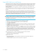
• 4 blinks - Configuration file system error blink pattern, page 37
• 5 blinks - Over temperature blink pattern, page 38
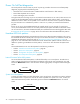
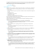
Internal firmware failure blink pattern
An internal firmware failure blink pattern is 2 blinks followed by a two second pause. The 2-blink error
pattern indicates that the firmware has failed, and that the switch must be reset. Momentarily press and
release the Maintenance button to reset the switch. Gather logging data, call support before resetting the
switch.
System error blink pattern
A system error blink pattern is 3 blinks followed by a two second pause. The 3-blink error pattern indicates
that a POST failure or a system error has left the switch inoperable. If a system error occurs, contact your
authorized maintenance provider. Momentarily press and release the Maintenance button to reset the
switch.
2 seconds
2 seconds