
McDATA® 4Gb SAN Switch for HP p-Class BladeSystem Installation Guide (AA-RW1XA-TE, June 2005)


McDATA® 4Gb SAN Switch for HP p-Class BladeSystem installation guide 35
4 Diagnostics and troubleshooting
Diagnostic information about the switch is available through the switch LEDs and the port LEDs. Diagnostic
information is also available through the McDATA Web Server and CLI event logs and error displays. This
section describes the following types of diagnostics:
• ”Switch diagnostics” on page 35 describes the Power LED and System Fault LED indications.
• ”Power On Self Test diagnostics” on page 36 describe the Heartbeat LED and the port Logged-in LED
indications.
This section also describes how to use maintenance mode to recover a disabled switch.
Switch diagnostics
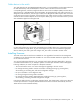
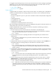
Switch diagnostics are indicated by the switch LEDs as shown in Figure 12.
Figure 12 Switch LED diagnostics
The following conditions are described:
• Power LED is extinguished, page 35
• System Fault LED is illuminated, page 35
Power LED is extinguished
The Power LED illuminates to indicate that the switch logic circuitry is receiving proper voltages. If the Power
LED is extinguished, contact your authorized maintenance provider.
System Fault LED is illuminated
The System Fault LED illuminates to indicate that the switch logic circuitry is overheating, or that a POST
error has occurred. The System Fault LED is always accompanied by a Heartbeat LED error blink code. If
the System Fault LED illuminates, identify the Heartbeat LED error blink pattern and take the necessary
actions. Refer to ”Heartbeat LED blink patterns” on page 36. The System Fault LED is also illuminated on
an internal firmware error, corrupt configuration, and voltage fault (input power never is turned off once the
switch is powered on even during a voltage fault).
Heartbeat LED
System Fault LED
Power LED