McDATA® 4Gb SAN Switch for HP p-Class BladeSystem command line interface guide Part number: AA-RWEJA-TE First edition: November 2006
Legal and notice information © Copyright 2006 Hewlett-Packard Development Company, L.P. © Copyright 2006 McDATA Corporation. © Copyright 2006. This software includes technology under a license from QLogic Corporation. All rights reserved. Hewlett-Packard Company makes no warranty of any kind with regard to this material, including, but not limited to, the implied warranties of merchantability and fitness for a particular purpose.
Contents About this guide . . . . . . . . . . . . . . . . . . . . . . . . . . . . . . . . . . . . . . . . . . . . . . . . . . . . . . . 9 Intended audience . . . . . . . . . . . . . . . . . . . . . . . . . . . . . . . . . . . . . . . . . . . . . . . . . . . . . . . . . . Prerequisites. . . . . . . . . . . . . . . . . . . . . . . . . . . . . . . . . . . . . . . . . . . . . . . . . . . . . . . . . . . . . . . Related documentation . . . . . . . . . . . . . . . . . . . . . . . . . . . . . . . . . . . . . . . .
Setting the date and time. . . . . . . . . . . . . . . . . . . . . . . . . . . . . . . . . . . . . . . . . . . . . . . . . . . . . . . Resetting a switch . . . . . . . . . . . . . . . . . . . . . . . . . . . . . . . . . . . . . . . . . . . . . . . . . . . . . . . . . . . . Installing firmware . . . . . . . . . . . . . . . . . . . . . . . . . . . . . . . . . . . . . . . . . . . . . . . . . . . . . . . . . . . Non-disruptive activation . . . . . . . . . . . . . . . . . . . . . . . . . . . . . . . . . . . . .
8 Device security configuration . . . . . . . . . . . . . . . . . . . . . . . . . . . . . . . . . . . . . . . . . . . 73 Displaying security database information. . . . . . . . . . . . . . . . . . . . . . . . . . . . . . . . . . . . . . . . . . . . . . Configured security set information . . . . . . . . . . . . . . . . . . . . . . . . . . . . . . . . . . . . . . . . . . . . . . . Active security set information . . . . . . . . . . . . . . . . . . . . . . . . . . . . . . . . . . . . . . . . . . . . . . . . .
Date command. . . . . . . . . . . . . . . . . . . . . . . . . . . . . . . . . . . . . . . . . . . . . . . . . . . . . . . . . . . . . . . . Exit command . . . . . . . . . . . . . . . . . . . . . . . . . . . . . . . . . . . . . . . . . . . . . . . . . . . . . . . . . . . . . . . . Fcping command . . . . . . . . . . . . . . . . . . . . . . . . . . . . . . . . . . . . . . . . . . . . . . . . . . . . . . . . . . . . . . Fctrace command . . . . . . . . . . . . . . . . . . . . . . . . . . . . . . . . . . . . . .
Show Port command . . . . . . . . . . . . . . . . . . . . . . . . . . . . . . . . . . . . . . . . . . . . . . . . . . . . . . . . . . Show Post Log command . . . . . . . . . . . . . . . . . . . . . . . . . . . . . . . . . . . . . . . . . . . . . . . . . . . . . . . Show Setup Mfg command . . . . . . . . . . . . . . . . . . . . . . . . . . . . . . . . . . . . . . . . . . . . . . . . . . . . . Show Setup Radius command . . . . . . . . . . . . . . . . . . . . . . . . . . . . . . . . . . . . . . . . . . . . . .
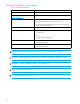
32 33 34 35 8 Port activity data . . . . . . . . . . . . . . . . . . . . . . . . . . . . . . . . . . . . . . . . . . . . . . . . . . . . . . . . . Switch operational parameters . . . . . . . . . . . . . . . . . . . . . . . . . . . . . . . . . . . . . . . . . . . . . . . Port test parameters . . . . . . . . . . . . . . . . . . . . . . . . . . . . . . . . . . . . . . . . . . . . . . . . . . . . . . . Zoning database limits . . . . . . . . . . . . . . . . . . . . . . . . . . . . . . . . . . . . . . . . . . .
About this guide The McDATA 4Gb SAN Switch is a 10-port non-blocking Fibre Channel (FC) switch. This guide describes the Command Line Interface (CLI) management tool for the switch and defines its features, components, and performance characteristics.
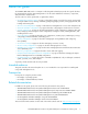
Document conventions and symbols Table 1 Document conventions Convention Element Medium blue text: Figure 1 Cross-reference links and e-mail addresses Medium blue, underlined text (http://www.hp.
HP technical support Telephone numbers for worldwide technical support are listed on the HP support web site: http://www.hp.com/support/. Collect the following information before calling: • Technical support registration number (if applicable) • Product serial numbers • Product model names and numbers • Applicable error messages • Operating system type and revision level • Detailed, specific questions For continuous quality improvement, calls may be recorded or monitored.
1 Command Line Interface Usage This section describes the following tasks: • Logging in to the switch, page 13 • Opening and closing an Admin session, page 14 • Entering commands, page 14 • Getting help, page 14 • Setting page breaks, page 15 • Creating a support file, page 15 • Downloading and uploading files, page 17 NOTE: Throughout this document, references in text to commands and operands use initial capitalization for clarity.
Opening and closing an Admin session The command line interface performs monitoring and configuration tasks. Commands that perform monitoring tasks are available to all user accounts. Commands that perform configuration tasks are available only after entering the Admin Start command to open an Admin session. A user account must have Admin authority to enter the Admin Start command. The following is an example of how to open and close an Admin session: McDATA4GbSAN #> admin start McDATA4GbSAN (admin) #> . .
Setting page breaks Some display commands deliver so much information to the screen that it scrolls off too quickly to read it. You can limit the display to 20 lines by turning on page breaks. By default, page breaks are turned off. The following is an example of how to turn page breaks on and off: McDATA4GbSAN #> set pagebreak on McDATA4GbSAN $> set pagebreak off See the ”Set Pagebreak command” on page 161.
If your workstation does not have an FTP server, enter the Create Support command to create the support file, and use FTP to download the support file from the switch to your workstation as shown in the following example: McDATA4GbSAN #> create support Log Msg:[Creating the support file - this will take several seconds] FTP the dump support file to another machine? (y/n): n To download the support file from the switch to the workstation, perform the following procedure: 1.
Downloading and uploading files There are several files that reside on the switch that you can download to the workstation for examination or for safekeeping. These files include the following: • Backup configuration file (configdata) • Log files (logfile) • Support files (dump_support.tgz) You can upload firmware image files or backup configuration files to the switch to reinstall firmware or restore a corrupted configuration. The switch uses FTP to exchange files between the switch and the workstation.
2 User Account Configuration User accounts and their respective passwords are the first line of switch security. A user account consists of an account name, an authority level, and an expiration date. Switches come from the factory with certain user accounts defined for special purposes. Table 3 describes these accounts, their passwords, and their purposes. These accounts cannot be deleted from the switch.
Displaying user account information You can display all user accounts defined on the switch (User Accounts command) or just those user accounts that are logged on (User List or Show Users commands). Account information includes account name, authority, and expiration date.
Modifying user accounts and passwords Only the Admin user account can modify a user account, delete a user account, or change the password of another user account. However, all user accounts can change their own passwords. The User command modifies and deletes user accounts. The Passwd command changes passwords. The following example removes the expiration date and admin authority for the user account named user1: McDATA4GbSAN (admin) #> user edit Press 'q' and the ENTER key to abort this command.
3 Network and fabric configuration The switch network configuration consists of the following: • Network discovery method • IP address • Subnet mask • IP gateway address The network discovery method determines how the switch acquires its IP address. The IP address can come from the IP address that resides on the switch or from a server.
Displaying name server information The Show Ns command displays the domain ID information for the fabric as shown in the following example: McDATA4GbSAN #> show ns all Seq Domain Port Port No ID ID Type COS PortWWN --- ----------- ---- --- ------No entries found for domain ID 1. Seq Domain Port No ID ID --- ----------No entries found for Port Type COS PortWWN ---- --- ------domain ID 4.
The Show Setup System command displays the switch network configuration as shown in the following example: McDATA4GbSAN #> show setup System Information -----------------EthNetworkEnable EthNetworkDiscovery EthNetworkAddress EthNetworkMask EthGatewayAddress AdminTimeout InactivityTimeout LocalLogEnabled RemoteLogEnabled RemoteLogHostAddress NTPClientEnabled NTPServerAddress EmbeddedGUIEnabled system True Static 10.20.11.32 255.255.252.0 10.20.8.254 30 0 True False 10.0.0.254 True 51.68.85.
Verifying a switch in the network You can verify that a switch is communicating in the network using the Ping command. The following example successfully tests the network for a switch with IP address 10.20.11.57: McDATA4GbSAN #> ping 10.20.11.57 Ping command issued. Waiting for response... McDATA4GbSAN #> Response successfully received from 10.20.11.57. If the switch is unreachable, you will see the following display: McDATA4GbSAN #> ping 10.20.11.57 Ping command issued. Waiting for response...
4 Switch configuration Switch configuration consists of the following tasks: • Displaying switch information, page 27 • Managing switch services, page 33 • Managing switch configurations, page 34 • Switch binding, page 38 • Paging a switch, page 39 • Setting the date and time, page 40 • Resetting a switch, page 41 • Installing firmware, page 41 • Managing switch feature upgrades, page 44 Displaying switch information You can display the following types of the switch information: • Switch operational infor
Switch operational information The Show Switch command displays a variety of switch operational information.
System process information The Ps displays system process information to help you determine what processes are running and CPU usage. The following example displays current system processes: McDATA4GbSAN #> ps PID 338 339 340 341 342 343 344 345 346 347 348 349 350 351 352 404 405 406 PPID %CPU TIME 327 0.0 00:00:00 327 0.0 00:00:01 327 0.0 00:00:21 327 0.1 00:05:35 327 0.2 00:11:29 327 0.0 00:00:04 327 0.0 00:02:16 327 0.0 00:02:44 327 0.8 00:35:12 327 0.0 00:00:29 327 0.0 00:02:46 327 0.0 00:00:21 327 5.
Configuration information The Show Config command displays a variety of configuration information at the port and switch levels. In addition to the basic switch configurations, the Show Config command displays parameters that control how data is maintained in the security and zoning databases.
Security configuration parameters Enter the Show Config Security command to display security configuration and port binding parameters. These parameters determine how security is applied to the switch. See Table 20 for a description of the switch security configuration parameters. See Table 21 for a description of the port binding parameters.
Hardware information Enter the Show Chassis command to display the status of the switch hardware including fans, power supplies, internal temperature, and Heartbeat LED status.
Managing switch services You can configure your switch to suit the demands of your environment by enabling or disabling a variety of switch services. You manage the switch services using the Show Setup Services and Set Setup Services commands. See Table 27 for a description of the switch services.
Managing switch configurations Successful management of switches and fabrics depends on the effective use of switch configurations. The switch configuration determines the basic operational characteristics of the switch. A switch supports up to 10 configurations including the default configuration, which is named Default Config. The current switch operating characteristics are determined by the active configuration. Only one configuration can be active at one time.
Modify a switch configuration To modify a switch configuration, you must open an Admin session with the Admin Start command. An Admin session prevents other accounts from making changes at the same time through Telnet, McDATA Web Server, or another management application. You must also open a Config Edit session with the Config Edit command and indicate which configuration you want to modify. If you do not specify a configuration name the active configuration is assumed.
Back up and restore a switch configuration Backing up and restoring a configuration is useful to protect your work or for use as a template in configuring other switches. Backing up and restoring the switch configuration involves the following: • Creating the backup file, page 36 • Downloading the configuration file, page 36 • Restoring the configuration file, page 36 Creating the backup file The Config Backup command creates a file on the switch, named configdata.
The restore process replaces all configuration information on the switch and afterwards the switch is automatically reset. If the restore process changes the IP address, all management sessions are terminated. Use the Set Setup System command to return the IP configuration to the values you want.
Switch binding IMPORTANT: Switch binding is available only with the McDATA SANtegrity Enhanced PFE key. See ”Managing switch feature upgrades” on page 44 for more information about installing a PFE key. To obtain the McDATA 4Gb SAN Switch serial number and PFE key, follow the step-by-step instructions on the firmware feature entitlement request certificate for the PFE key. You can obtain a PFE key from the web at: www.webkey.external.hp.com.
The Set Config Security Switchbinding command is used to enable switch binding and to specify the WWNs of the authorized ports/devices. The following example enables switch binding for devices and switches, and specifies two WWNs. McDATA4GbSAN #> admin start McDATA4GbSAN (admin) #> config edit The config named default is being edited. McDATA4GbSAN (admin-config) #> set config security switchbinding A list of attributes with formatting and current values will follow.
Setting the date and time The switch date and time can be set explicitly using the Date command or can be set automatically through a Network Time Protocol (NTP) server. The Date command also displays the current time. Unlike the Date command, the NTP server also synchronizes the date and time on the switch with the date and time on the workstation. Synchronized date and time is required for Secure Socket Layer (SSL) connections.
Resetting a switch Table 5 describes the methods for resetting a switch, the corresponding command, and the impact on the switch.
Non-disruptive activation You can load and activate new firmware on a switch disruptively or non-disruptively depending on the condition of the fabric and the commands you choose. If you attempt to perform a non-disruptive activation without satisfying the following conditions, the activation will fail. If the non-disruptive activation fails, you will usually be prompted to try again later. If you are not prompted to try again later, the switch will perform a disruptive activation.
3. Enter your account name on the remote host (FTP only) and the IP address of the remote host. When prompted for the source file name, enter the path for the firmware image file. User Account : johndoe IP Address : 10.0.0.254 Source Filename : 6.4.00.11_mpc About to install image. Do you want to continue? [y/n] y 4. When prompted to install the new firmware, enter Yes to continue or No to cancel. Entering Yes will disrupt traffic. This is the last opportunity to cancel. About to install image.
Managing switch feature upgrades Additional features are available to upgrade your switch through the purchase of a Product Feature Enablement (PFE) key, which is a password you can purchase from your switch distributor or authorized reseller. The following features are available with a PFE key: • The SANtegrity Enhanced® PFE key enables device security on the switch.
Installing a feature license Enter the Feature Add command within an Admin session to install a license key on your switch as shown in the following example: McDATA4GbSAN #> admin start McDATA4GbSAN (admin) #> feature add 120-LCGYKRFCH8WNC Switch already licensed for McDATA Fabric Mode License upgrade for EFCM capability This feature upgrade does NOT require a switch reset. Do you want to continue with license upgrade procedure? (y/n): [n] y Log Msg: [Mon Jul 31 10:08:29.520 CDT 2006][C][8400.
5 Port configuration This section describes the following port configuration tasks: • Displaying port information, page 47 • Modifying port operating characteristics, page 51 • Port binding, page 52 • Resetting a port, page 53 • Configuring port threshold alarms, page 53 • Testing a port, page 55 Displaying port information You can display the following port information: • Port configuration parameters, page 47 • Port operational information, page 48 • Port threshold alarm configuration parameters, page 4
Port operational information Enter the Show Port command to display port operational information.
Port threshold alarm configuration parameters Enter the Show Config Threshold command to display the port threshold alarm parameters. These parameters determine the error thresholds at which the switch issues alarms. Refer to Table 24 for a description these parameters.
Port performance Enter the Show Perf command to display port performance in terms of the volume of data transmitted, data received, or errors. You can display continuous live performance information for one or more ports, or an instantaneous summary. The following example displays an instantaneous summary in bytes and frames. Values are expressed in thousands (K) and millions (M) of bytes or frames per second.
Modifying port operating characteristics You can make permanent or temporary changes to port operating characteristics. You make permanent changes by modifying the switch configuration as described in ”Modify a switch configuration” on page 35. These changes are saved in the active configuration and are preserved across switch or port resets. The Set Port command makes temporary changes that apply until the next port or switch reset, or until you activate a configuration.
Port binding Port binding establishes up to 32 switches or devices that are permitted to log in to a particular switch port. Switches or devices that are not among the 32 are refused access to the port. You apply port binding changes by modifying the switch configuration as described in ”Modify a switch configuration” on page 35.
Resetting a port Enter the Reset Port command to reinitialize one or more ports and to discard any temporary changes that have been made to the administrative state or link speed. The following example reinitializes port 0: McDATA4GbSAN #> reset port 0 See the ”Reset command” on page 132. Configuring port threshold alarms The switch can monitor a set of port errors and generate alarms based on user-defined sample windows and thresholds.
Enter the Set Config Threshold command within an Admin session to enable and configure port threshold monitoring on the switch as shown in the following example: McDATA4GbSAN #> admin start McDATA4GbSAN (admin) #> config edit McDATA4GbSAN (admin-config) #> set config threshold A list of attributes with formatting and current values will follow. Enter a new value or simply press the ENTER key to accept the current value.
Testing a port You can test a port using the Test Port command within an Admin session using online or offline tests. The following sections describe the port test types, how to display port test results, and how to cancel a port test: • Online tests for ports, page 55 • Offline tests for ports, page 56 • Display port tests results, page 56 • Cancel a port test, page 56 Online tests for ports An online test is a non-disruptive test that exercises the port, transceiver, and device connections.
Offline tests for ports An offline test is a disruptive test that exercises the port connections. You must place the port in the diagnostics state using the Set Port command before starting the test. There are two types of offline tests: internal loopback and external loopback. • An internal loopback test exercises the internal port connections. • An external loopback test exercises the port and its transceiver. A transceiver with a loopback plug is required for this test.
6 Zoning configuration This section describes the following tasks: • Displaying zoning database information, page 58 • Configuring the zoning database, page 63 • Modifying the zoning database, page 64 • Resetting the zoning database, page 64 • Managing zone sets, page 65 • Managing zones, page 67 Consider device access needs within the fabric. Access is controlled by the use of zoning. Some zoning strategies include the following: • Separate devices by operating system.
Displaying zoning database information You can display the following information about the zoning database: • Configured zone set information, page 58 • Active zone set information, page 60 • Zone set membership information, page 60 • Zoning modification history, page 61 • Zoning database limits, page 62 Configured zone set information The Zoneset List and the Zoning List commands display information about the all zone sets in the zoning database.
Enter the Zoning List command to display all zone sets, zones, and zone members in the zoning database as shown in the following example: McDATA4GbSAN #> zoning list Active ZoneSet Information ZoneSet Zone ZoneMember -------------------------------wwn wwn_b0241f 50:06:04:82:bf:d2:18:c2 50:06:04:82:bf:d2:18:d2 21:00:00:e0:8b:02:41:2f wwn_23bd31 50:06:04:82:bf:d2:18:c2 50:06:04:82:bf:d2:18:d2 10:00:00:00:c9:23:bd:31 wwn_221416 50:06:04:82:bf:d2:18:c2 50:06:04:82:bf:d2:18:d2 10:00:00:00:c9:22:14:16 wwn_2215c3
Active zone set information The Zoning Active and Zoneset Active commands display information about the active zone set.
Enter the Zone Zonesets command to display the zone sets for which a specified zone is a member as shown in the following example: McDATA4GbSAN #> zone zonesets zone1 Current List of ZoneSets for Zone: zone1 ---------------------------------zone_set_1 See the ”Zone command” on page 223.
Zoning database limits Enter the Zoning Limits command to display a summary of the objects in the zoning database and their maximum limit as shown in the following example: McDATA4GbSAN #> zoning limits Zoning Attribute ---------------MaxZoneSets MaxZones MaxTotalMembers MaxZonesInZoneSets MaxMembersPerZone Maximum ------1 2047 10000 2047 4096 See the ”Zoning command” on page 228.
Configuring the zoning database You can configure how the zoning database is applied to the switch and exchanged with the fabric through the switch and zoning configuration parameters. The following zoning configuration parameters are available through the Set Config Zoning command and are described in more detail in Table 25: • InteropAutoSave–This parameter enables or disables the saving of changes to the active zone set in the switch’s permanent memory.
Modifying the zoning database To modify the zoning database, you must open an Admin session with the Admin Start command. An Admin session prevents other accounts from making changes at the same time through Telnet, McDATA Web Server, or another management application. You must also open a Zoning Edit session with the Zoning Edit command. The Zoning Edit session provides access to the Zoneset, Zone, and Zoning commands with which you make modifications to the zoning database.
Managing zone sets Managing zone sets consists of the following tasks: • Create a zone set, page 65 • Delete a zone set, page 65 • Rename a zone set, page 65 • Add zones to a zone set, page 65 • Remove zones from a zone set, page 65 • Activate a zone set, page 66 • Deactivate a zone set, page 66 All of these tasks except ”Activate a zone set” and ”Deactivate a zone set” require an Admin session and a Zoning Edit session. See the ”Zoneset command” on page 226.
Activate a zone set Enter the Zoneset Activate command to apply zoning to the fabric as shown in the following example: McDATA4GbSAN #> admin start McDATA4GbSAN (admin) #> zoneset activate zoneset_1 Deactivate a zone set Enter the Zoneset Deactivate command to deactivate the active zone set and disable zoning in the fabric: McDATA4GbSAN #> admin start McDATA4GbSAN (admin) #> zoneset deactivate 66
Managing zones Managing zones consists of the following tasks: • Create a zone, page 67 • Delete a zone, page 67 • Rename a zone, page 67 • Copy a zone, page 67 • Add members to a zone, page 67 • Remove members from a zone, page 68 All of these tasks require an Admin session and a Zoning Edit session. See the ”Zone command” on page 223.
Remove members from a zone Enter the Zone Remove command to remove ports/devices from zone_1 as shown in the following example: McDATA4GbSAN McDATA4GbSAN McDATA4GbSAN McDATA4GbSAN 68 #> admin start (admin) #> zoning edit (admin-zoning) #> zone remove zone_1 1,4 1,5 (admin-zoning) #> zoning save
7 Connection security This section describes the following tasks: • Managing SSL and SSH services, page 70 • Displaying SSL and SSH services, page 71 • Creating an SSL security certificate, page 71 The switch supports secure connections with Telnet and switch management applications. The Secure Shell protocol (SSH) secures Telnet connections to the switch.
Managing SSL and SSH services Consider the following when enabling SSH and SSL services: • To establish a secure Telnet connection, your workstation must use an SSH client. • To enable secure SSL connections, you must first synchronize the date and time on the switch and workstation. Refer to ”Setting the date and time” on page 40. • The SSL service must be enabled to authenticate users through a RADIUS server. Refer to ”Configuring a RADIUS server on the switch” on page 86.
Displaying SSL and SSH services Enter the Show Setup Services command to display the status of the SSH and SSL services as shown in the following example: McDATA4GbSAN #> show setup services System Services ----------------------------TelnetEnabled True SSHEnabled False GUIMgmtEnabled True SSLMgmtEnabled False EmbeddedGUIEnabled True SNMPEnabled True NTPEnabled True CIMEnabled True FTPEnabled True MgmtServerEnabled True See the ”Show Setup Services command” on page 204.
8 Device security configuration IMPORTANT: Device security is available only with the McDATA SANtegrity PFE key. See ”Managing switch feature upgrades” on page 44 for more information about installing a PFE key. To obtain the McDATA 4Gb SAN Switch serial number and PFE key, follow the step-by-step instructions on the firmware feature entitlement request certificate for the PFE key. You can obtain a PFE key from the web at: www.webkey.external.hp.com.
Configured security set information The Securityset List and the Security List commands display information about the all security sets in the security database. Enter the Securityset List command to display a list of the security sets as shown in the following example: McDATA4GbSAN #> securityset list Current list of SecuritySets ---------------------------alpha beta See the ”Securityset command” on page 142.
Active security set information The Security Active and Securityset Active commands display information about the active security set.
Security set membership information The Securityset Groups and Group Securitysets commands display security set membership information.
Security database modification history Enter the Security History command to display a record of security database modifications as shown in the following example: McDATA4GbSAN #> security history Active Database Information --------------------------SecuritySetLastActivated/DeactivatedBy SecuritySetLastActivated/DeactivatedOn Database Checksum Inactive Database Information ----------------------------ConfigurationLastEditedBy ConfigurationLastEditedOn Database Checksum Remote day month date time year 0000
Configuring the security database You can configure how the security database is applied to the switch and exchanged with the fabric through the security configuration parameters. The following security configuration parameters are available through the Set Config Security command: • AutoSave–This parameter enables or disables the saving of changes to the active security set in the switch’s permanent memory.
Modifying the security database To modify the security database, you must open an Admin session with the Admin Start command. An Admin session prevents other accounts from making changes at the same time either through Telnet or McDATA Web Server. You must also open a Security Edit session with the Security Edit command. The Security Edit session provides access to the Securityset, Group, and Security commands with which you make modifications to the security database.
Managing security sets Managing security sets consists of the following tasks: • Create a security set, page 80 • Delete a security set, page 80 • Rename a security set, page 80 • Copy a security set, page 80 • Add groups to a security set, page 80 • Remove groups from a security set, page 80 • Activate a security set, page 80 • Deactivate a security set, page 80 All of these tasks except ”Activate a security set” and ”Deactivate a security set” require a Security Edit session.
Managing groups Managing groups consists of the following tasks: • Create a group, page 81 • Delete a group, page 81 • Rename a group, page 81 • Copy a group, page 81 • Add members to a group, page 82 • Modify a group member, page 82 • Remove members from a group, page 83 All of these tasks require an Admin session and a Security Edit session. See the ”Group command” on page 113. Create a group Creating a group involves specifying a group name and a group type.
Add members to a group Adding a member to a group involves specifying a group, the member WWN, and the member attributes. The member attributes define the authentication method, encryption method, secrets, and fabric binding, depending on the group type. • For ISL Group member attributes, refer to Table 6. • For Port Group member attributes, refer to Table 7. • For MS Group member attributes, refer to Table 8.
Remove members from a group Enter the Group Remove command to remove a member from a group as shown in the following example: McDATA4GbSAN (admin-security) #> group remove group_1 10:00:00:c0:dd:00:90:a3 McDATA® 4Gb SAN Switch for HP p-Class BladeSystem command line interface guide 83
9 RADIUS server configuration Authentication can be performed locally using the switch’s security database, or remotely using a Remote Dial-In User Service (RADIUS) server such as Microsoft RADIUS. With a RADIUS server, the security database for the entire fabric resides on the server. In this way, the security database can be managed centrally, rather than on each switch. You can configure up to five RADIUS servers to provide failover.
Configuring a RADIUS server on the switch Enter the Set Setup Radius command to configure a RADIUS server on the switch as shown in the following example. Refer to Table 26 for a description of the RADIUS server configuration parameters. McDATA4GbSAN (admin) #> set setup radius A list of attributes with formatting and current values will follow. Enter a new value or simply press the ENTER key to accept the current value.
10 Event log configuration This section describes the following tasks: • Starting and stopping event logging, page 87 • Displaying the event log, page 88 • Managing the event log configuration, page 90 • Clearing the event log, page 91 • Logging to a remote host, page 91 • Creating and downloading a log file, page 92 Event messages originate from the switch or from the management application in response to events that occur in the fabric.
Displaying the event log Enter the Show Log command to display the event log. Each message has the following format: [ordinal][time_stamp][severity][message_ID][source][message_text] [ordinal]—A number assigned to each message in sequence since the last time the alarm history was cleared [time_stamp]—The time the alarm was issued in the format day month hh:mm:ss.ms UTC yyyy.
Filtering the event log display You can customize what events are displayed according to the component or severity level. Enter the Show Log Display command to filter the events in the display.
Managing the event log configuration Managing the event log configuration consists of the following tasks: • Configure the event log, page 90 • Display the event log configuration, page 90 • Restore the event log configuration, page 90 Configure the event log You can customize what events are recorded in the switch event log according to component, severity level, and port. Enter the Set Log Component, Set Log Level, and Set Log Port commands to filter the events to be recorded.
Clearing the event log Enter the Set Log Clear command to delete all entries in the event log as shown in the following example: McDATA4GbSAN (admin) #> set log clear See the ”Set Log command” on page 158. Logging to a remote host The switch comes from the factory with local logging enabled, which instructs the switch firmware to maintain an event log in switch memory. The switch can also be configured to log events to a remote host that supports the syslog protocol.
Creating and downloading a log file Enter the Set Log Archive command to collect the event log messages in a file on the switch named logfile. This file can have a maximum of 1200 event messages. Use FTP to download the file from the switch to your workstation as follows: 1. Log into the switch through Telnet and create an archive of the event log. The Set Log Archive command creates a file on the switch named logfile. McDATA4GbSAN #> admin start McDATA4GbSAN (admin) #> set log archive 2.
11 Simple Network Management Protocol configuration The Simple Network Management Protocol (SNMP) provides for the management of the switch through third-party applications that use SNMP. Security consists of a read community string and a write community string which serve as passwords that control read and write access to the switch. These strings are set at the factory to well-known defaults and should be changed if SNMP is to be enabled.
Displaying SNMP information Enter the Show Setup Snmp command to display SNMP configuration information as shown in the following example. Refer to Table 28 for a description of the SNMP parameters. McDATA4GbSAN #> show setup snmp SNMP Information ---------------SNMPEnabled True Contact Location System Lab Description McDATA 4Gb SAN Switch Trap1Address 10.0.0.254 Trap1Port 162 Trap1Severity warning Trap1Version 2 Trap1Enabled False Trap2Address 0.0.0.
Modifying the SNMP configuration Enter the Set Setup Snmp command within an Admin session to modify the SNMP configuration as shown in the following example. Refer to Table 28 for descriptions of SNMP parameters. McDATA4GbSAN #> admin start McDATA4GbSAN (admin) #> set setup snmp A list of attributes with formatting and current values will follow. Enter a new value or simply press the ENTER key to accept current value.
Resetting the SNMP configuration Enter the Reset Snmp command within and Admin session to reset the SNMP configuration back to the factory defaults as shown in the following example. Refer to Table 14 for a listing of the SNMP configuration factory defaults. McDATA4GbSAN (admin) #> reset snmp See the ”Reset command” on page 132.
12 Command reference This chapter describes the commands of the CLI, the formats in which they are presented, and the following information for each: • Access authority, page 97 • Syntax and operands, page 97 • Notes and examples, page 97 The commands are listed in ”Command listing” on page 98. Access authority The Authority paragraph in each command description indicates what types of sessions are required to enter that command.
Command listing The commands are listed in alphabetical order as follows: A Passwd command Ping command Ps command Set Config Zoning command Set Log command Set Pagebreak command Set Port command Set Setup Radius command Set Setup Services command Set Setup SNMP command, Set Setup System command Set Switch State command Set Timezone command Show About command Show Alarm command Show Broadcast command Show Chassis command Show Domains command Show Fabric command Show FDMI command Show Interface command Sho
Admin command Description Starts and ends an Admin session. The Admin session allows commands that change the fabric and switch configurations. Only one Admin session can be started on the switch at any time. An idle Admin session will timeout after a set period of time (the default is 30 minutes) which can be changed using the Set Setup System command. Authority User account with Admin authority Syntax admin start (or begin) end (or stop) cancel Operands start or begin Opens the Admin session.
Config command Description Manages the FC configurations on a switch. For information about setting the port and switch configurations, see the Set Config Switch command. Authority Admin session for all operands except List. Syntax config activate [config_name] backup cancel copy [config_source] [config_destination] delete [config_name] edit [config_name] list restore save [config_name] Operands activate [config_name] Activates the configuration given by [config_name].
restore Restores configuration settings to an out-of-band switch from a backup file named configdata, which must be first uploaded on the switch using FTP. You create the backup file using the Config Backup command. Use FTP to load the backup file on a switch, then enter the Config Restore command. After the restore is complete, the switch automatically resets. See ”Back up and restore a switch configuration” on page 36. NOTE: All management sessions are terminated because the switch is reset.
The following is an example of how to upload a configuration backup file (configdata) from the workstation to the switch, and then restore the configuration: #> ftp symbolic_name or ip_address user: images password: images ftp> bin ftp> put configdata ftp> quit McDATA4GbSAN #> admin start McDATA4GbSAN (admin) #> config restore The switch will be reset after restoring the configuration. Please confirm (y/n): [n] y Alarm Msg: [day month date time year][A1005.
Create command Description Creates support files for troubleshooting switch problems and certificates for secure communications for McDATA Web Server and Element Manager. Authority Admin session Syntax create certificate support Operands certificate Creates a security certificate on the switch. The security certificate is required to establish an SSL connection with a management application such as McDATA Web Server.
Examples The following is an example of the Create Support command when an FTP server is available on the workstation: McDATA4GbSAN #> create support Log Msg:[Creating the support file - this will take several seconds] FTP the dump support file to another machine? (y/n): y Enter IP Address of remote computer: 10.20.33.130 Login name: johndoe Enter remote directory name: bin/support Would you like to continue downloading support file? (y/n) [n]: y Connected to 10.20.33.130 (10.20.33.130). 220 localhost.
The following is an example of the Create Certificate command: McDATA4GbSAN (admin) #> create certificate The current date and time is day mon date hh:mm:ss UTC yyyy. This is the time used to stamp onto the certificate. Is the date and time correct? (y/n): [n] y Certificate generation successful.
Date command Description This command displays or sets the system date and time. To set the date and time the information string must be provided in this format: MMDDhhmmCCYY. The new date and time takes effect immediately. Authority Admin session except to display the date. Syntax date [MMDDhhmmCCYY] Operands [MMDDhhmmCCYY] Specifies the date – this requires an Admin session. If you omit [MMDDhhmmCCYY], the current date is displayed, which does not require an Admin session.
Exit command Description Closes the Telnet session Authority None Syntax exit Notes You can also press Control-D to close the Telnet session.
Fcping command Description Verifies an FC connection with another switch or a device and reports status. Authority None Syntax fcping destination [address] count [number] timeout [seconds] Operands [address] The address of the port or device with which to verify the Fibre Channel connection. [address] can have one of the following formats: • 6-character hexadecimal device FC address (hex). Enter addresses with or without the “0x” prefix.
Fctrace command Description Displays the path from one port in the fabric to another in the same zone. Path information includes the following: • Domain IDs • Incoming port name and physical port number • Outgoing port name and physical port number Authority None Syntax fctrace [port_source] [port_destination] [hop_count] Operands [port_source] The FC port from which to begin the trace. [port_source] can have the following formats: • 6-character hexadecimal device FC address (hex).
Feature command Description Adds Product Feature Enablement (PFE) key features to the switch and displays the PFE key log. A PFE key is a password that you can purchase from your switch distributor or authorized reseller to enable particular features in your switch. Authority Admin session for Add operand only Syntax feature add [pfe_key] log Operands add [pfe_key] Adds the feature that corresponds to the value given by [pfe_key]. [pfe_key] is case insensitive.
Firmware Install command Description Downloads firmware from a remote host to the switch, installs the firmware, then resets the switch (without a POST) to activate the firmware.
The following is an example of the Firmware Install command using TFTP: McDATA4GbSAN #> admin start McDATA4GbSAN (admin) #> firmware install The switch will be reset. This process will cause a disruption to I/O traffic. Continuing with this action will terminate all management sessions, including any Telnet sessions. When the firmware activation is complete, you may log in to the switch again. Do you want to continue? [y/n]: y Press 'q' and the ENTER key to abort this command.
Group command Description Creates groups, manages membership within the group, and manages the membership of groups in security sets. IMPORTANT: This command is available only with the SANtegrity Enhanced PFE key. Authority Admin session and a Security Edit session. See the Security command for information about starting a Security Edit session. The List, Members, Securitysets, and Type operands are available without an Admin session.
Table 6 ISL Group member attributes (Continued) Attribute Description Secondary Hash Hash function to use to decipher the encrypted Secondary Secret sent by the ISL group member. Hash values are MD5 or SHA-1. The Secondary Hash is used when the Primary Hash is not available on the ISL group member. The Primary Hash and the Secondary Hash cannot be the same. NOTE: Secondary Hash is not supported when connecting to other McDATA products.
Table 7 Port Group member attributes (Continued) Attribute Description Secondary Hash Hash function to use to decipher the encrypted Secondary Secret sent by the Port group member. Hash values are MD5 or SHA-1. The Secondary Hash is used when the Primary Hash is not available on the Port group member. The Primary Hash and the Secondary Hash cannot be the same. NOTE: Secondary Hash is not supported when connecting to other McDATA products.
edit [group] [member] Initiates an editing session in which to change the attributes of a WWN given by [member] in a group given by [group]. Member attributes that can be changed are described in Table 9. Table 9 Group member attributes Attribute Description Authentication Enables (CHAP) or disables (None) authentication using Challenge Handshake Authentication Protocol. The default is None.
list Displays a list of all groups and the security sets of which they are members. This operand is available without an Admin session. members [group] Displays all members of the group given by [group]. This operand is available without an Admin session. remove [group] [member_list] Remove the port/device WWN given by [member] from the group given by [group].
The following is an example of the Group Edit command: McDATA4GbSAN (admin-security) #> group edit G1 10:00:00:c0:dd:00:90:a3 A list of attributes with formatting and current values will follow. Enter a new value or simply press the ENTER key to accept the current value. If you wish to terminate this process before reaching the end of the list press 'q' or 'Q' and the ENTER key to do so.
Hardreset command Description Resets the switch and performs a POST. This reset disrupts traffic, activates the pending firmware, and clears the alarm log. To save the alarm log before resetting, see the Set Log command. Authority Admin session Syntax hardreset Notes To reset the switch without a POST, see the Reset command. To reset the switch without disrupting traffic, see the Hotreset command.
Help command Description Displays a brief description of the specified command, its operands, and usage. Authority None Syntax help [command] [operand] Operands [command] Displays a summary of the command given by [command] and its operands. If you omit [command], the system displays all available commands. [operand] Displays a summary of the operand given by [operand] belonging to the command given by [command].
History command Description Displays a numbered list of the previously entered commands from which you can re-execute selected commands. Authority None Syntax history Notes Use the History command to provide context for the ! command: • Enter ![command_string] to re-execute the most recent command that matches [command_string].
Hotreset command Description Resets the switch for the purpose of activating the pending firmware without disrupting traffic. This command terminates all management sessions, saves all configuration information, and clears the event log. After the pending firmware is activated, the configuration is recovered. This process takes less than 80 seconds. To save the event log to a file before resetting, see the Set Log command.
Image command Description Manages and installs switch firmware. Authority Admin session Syntax image cleanup fetch [account_name] [ip_address] [file_source] [file_destination] install list tftp [ip_address] [file_source] [file_destination] unpack [file] Operands cleanup Removes all firmware image files from the switch. All firmware image files are removed automatically each time the switch is reset.
Notes To provide consistent performance throughout the fabric, ensure that all switches are running the same version of firmware. To install firmware when the management workstation has an FTP server, use the Image Install command or the Firmware Install command. To install firmware when the management workstation does not have an FTP server, perform the following procedure: 1. Connect to the switch through the Ethernet port. 2.
Examples The following is an example of the Image Install command: McDATA4GbSAN #> admin start McDATA4GbSAN (admin) #> image install Warning: Installing new firmware requires a switch reset. Continuing with this action will terminate all management sessions, including any Telnet sessions. When the firmware activation is complete, you may log in to the switch again. Do you want to continue? [y/n]: y Press 'q' and the ENTER key to abort this command. FTP or TFTP : ftp User Account : johndoe IP Address : 10.
Lip command Description Re-initializes the specified loop port. Authority Admin session Syntax lip [port_number] Operands [port_number] The number of the port to be re-initialized.
Logout command Description Closes the Telnet session Authority None Syntax logout Notes You can also press Control-D to close the Telnet session.
Passwd command Description Changes a user account’s password. Authority Admin account name and an Admin session to change another account’s password. You can change your own password without an Admin session. Syntax passwd [account_name] Operands [account_name] The user account name. To change the password for an account name other than your own, you must open an Admin session with the account name admin.
Ping command Description Initiates an attempt to communicate with another switch over an Ethernet network and reports the result. Authority None Syntax ping [ip_address] Operands [ip_address] The IP address of the switch you want to query. Broadcast IP addresses, such as 255.255.255.255, are not valid. Examples The following is an example of a successful Ping command: McDATA4GbSAN #> ping 10.20.11.57 Ping command issued. Waiting for response...
Ps command Description Displays current system process information. Authority None Syntax ps Examples The following is an example of the Ps command: McDATA4GbSAN #> ps PID 338 339 340 341 342 343 344 345 346 347 348 349 350 351 352 404 405 406 130 PPID %CPU TIME 327 0.0 00:00:00 327 0.0 00:00:01 327 0.0 00:00:21 327 0.1 00:05:35 327 0.2 00:11:29 327 0.0 00:00:04 327 0.0 00:02:16 327 0.0 00:02:44 327 0.8 00:35:12 327 0.0 00:00:29 327 0.0 00:02:46 327 0.0 00:00:21 327 5.6 04:08:24 327 0.
Quit command Description Closes the Telnet session. Authority None Syntax quit Notes You can also press Control+D to close the Telnet session.
Reset command Description Resets the switch configuration parameters. If you omit the operand, the default is Reset Switch. Authority Admin session Syntax reset config [config_name] factory port [port_number] radius security services snmp switch (default) system zoning Operands config [config_name] Resets the configuration given by [config_name] to the factory default values for switch, port, port threshold alarm, and zoning configuration as described in Table 10 through Table 13.
switch Resets the switch without a POST. This is the default. This reset disrupts traffic and does the following: • Activates the pending firmware • Closes all management sessions • Clears the event log. To save the event log before resetting, see the Set Log command To reset the switch with a POST, see the Hardreset command. To reset the switch without disrupting traffic, see the Hotreset command. system Resets the system configuration settings to the factory default values.
Enter the Show Config Port command to display port configuration values.
Enter Show Config Threshold command to display threshold alarm configuration values.
Enter the Show Config Zoning command to display zoning configuration values. Table 13 Zoning configuration defaults Parameter Default InteropAutoSave True DefaultZone False Enter the Show Setup SNMP command to display SNMP configuration values. Table 14 SNMP configuration defaults Parameter Default SNMPEnabled True Contact Location Description McDATA 4Gb SAN Switch Trap [1-5] Address Trap 1: 10.0.0.254; Traps 2–5: 0.0.0.
Enter the Show Setup Services command to display switch service configuration values. Table 16 Switch services configuration defaults Parameter Default TelnetEnabled True SSHEnabled False GUIMgmtEnabled True SSLMgmtEnabled False EmbeddedGUIEnabled True SNMPEnabled True NTPEnabled False CIMEnabled True FTPEnabled True MgmtServerEnabled False Enter the Show Setup System command to display system configuration values.
Enter the Show Config Security command to display security configuration values.
Security command Description Opens a Security Edit session in which to manage the security database on a switch. IMPORTANT: This command is available only with the SANtegrity Enhanced PFE key. Authority Admin session. The operands active, history, limits, and list are available without an Admin session. Syntax security active cancel clear edit history limits list restore save Operands active Displays the active security set, its groups, and group members.
save Saves the changes that have been made to the security database during a Security Edit session. Changes that you make to any security set will not take effect until you activate that security set. See the Securityset command for information about activating a security set.
The following is an example of the Security List command: McDATA4GbSAN #> security list Active Security Information SecuritySet Group GroupMember ----------- ----- ----------No active securityset defined.
Securityset command Description Manages security sets in the security database. NOTE: This command is available only with the SANtegrity Enhanced PFE key. Authority Admin session and a Security Edit session. See the Security command for information about starting a Security Edit session. The active, groups, and list operands are available without an Admin session. You must end the Security Edit session before using the activate and deactivate operands.
list Displays a list of all security sets. This operand is available without an Admin session. remove [security_set] [group] Removes a group given by [group] from the security set given by [security_set]. If [security_set] is the active security set, the group will not be removed until the security set has been deactivated. rename [security_set_old] [security_set_new] Renames the security set given by [security_set_old] to the name given by [security_set_new].
Set Alarm command Description Controls the display of alarms in the session output stream or clears the alarm log. Authority Admin session for the Clear operand. Otherwise, none. Syntax set alarm [option] Operands [option] can be one of the following: clear Clears the alarm log history. This value requires an Admin session. on Enables the display of alarms in the session output stream. off Disables the display of alarms in the session output stream.
Set Beacon command Description Enables or disables the flashing of the Logged-In LEDs. Authority None Syntax set beacon [state] Operands [state] can be one of the following: on Enables the flashing beacon. off Disables the flashing beacon.
Set Config Port command Description Sets the port configuration parameters for one or more ports. The changes you make with this command are not retained when you reset or power cycle the switch unless you save them using the Config Save command.
Table 19 Set Config Port parameters (Continued) Parameter Description ForceOfflineRSCN Enables (False) or disables (True) the immediate transmission of RSCN messages when communication between a port and a device is interrupted. If enabled, the RSCN message is delayed for 200 ms for locally attached devices and 400 ms for devices connected through other switches. The default is False. ARB_FF Send ARB_FF (True) instead of IDLEs (False) on the loop. The default is False.
Examples The following is an example of the Set Config Port command: McDATA4GbSAN #> admin start McDATA4GbSAN (admin) #> config edit McDATA4GbSAN (admin-config) #> set config port 0 A list of attributes with formatting and current values will follow. Enter a new value or simply press the ENTER key to accept the current value. If you wish to terminate this process before reaching the end of the attributes for the port being processed, press 'q' or 'Q' and the ENTER key to do so.
Set Config Security command Description Configures the security database for the automatic saving of changes to the active security set and fabric binding. The changes you make with this command are not retained when you reset or power cycle the switch unless you save them using the Config Save command. IMPORTANT: This command is available only with the SANtegrity Enhanced PFE key.
Set Config Security Portbinding command Description Configures a list of device WWNs that are permitted to log in to a port. The changes you make with this command are not retained when you reset or power cycle the switch unless you save them using the Config Save command.
Set Config Security Switchbinding command Description Configures a list of device WWNs that are permitted to log in to the switch. The changes you make with this command are not retained when you reset or power cycle the switch unless you save them using the Config Save command. Authority Admin session and a Config Edit session Syntax set config security switchbinding This command initiates an editing session in which to change the binding configuration for the switch.
Examples The following is an example of the Set Config Security Switchbinding command: McDATA4GbSAN #> admin start McDATA4GbSAN (admin) #> config edit The config named default is being edited. McDATA4GbSAN (admin-config) #> set config security switchbinding A list of attributes with formatting and current values will follow. Enter a new value or simply press the ENTER key to accept the current value.
Set Config Switch command Description Sets the switch configuration parameters. The changes you make with this command are not retained when you reset or power cycle the switch unless you save them using the Config Save command. Authority Admin session and a Config Edit session Syntax set config switch This command initiates an editing session in which to change switch configuration settings. The system displays each parameter one line at a time and prompts you for a value.
Table 23 Set Config Switch parameters (Continued) Parameter Description InteropMode Interoperability mode. This setting must be the same on all switches in the fabric, otherwise the inter-switch links will not connect. Choose from the following: • Use Standard to connect to FC-SW-2-compliant switches including McDATA switches in Open Fabric Mode. This is the default. • Use the McDATA Fabric Mode to connect to McDATA switches in McDATA Fabric Mode. 239DomainSupport Examples 239 domain ID support.
Set Config Threshold command Description Sets the port alarm threshold parameters by which the switch monitors port performance and generates alarms. The changes you make with this command are not retained when you reset or power cycle the switch unless you save them using the Config Save command. Authority Admin session and a Config Edit session Syntax set config threshold This command initiates a configuration session by which to generate and log alarms for selected events.
Examples The following is an example of the Set Config Threshold command: McDATA4GbSAN #> admin start McDATA4GbSAN (admin) #> config edit McDATA4GbSAN (admin-config) #> set config threshold A list of attributes with formatting and current values will follow. Enter a new value or simply press the ENTER key to accept the current value. If you wish to terminate this process before reaching the end of the list press 'q' or 'Q' and the ENTER key to do so.
Set Config Zoning command Description Configures the zoning database. The changes you make with this command are not retained when you reset or power cycle the switch unless you save them using the Config Save command. Authority Admin session and a Config Edit session Syntax set config zoning This command initiates an editing session in which to change the zoning database configuration. The system displays each parameter one line at a time and prompts you for a value.
Set Log command Description Specifies the events to record in the event log and display on the screen. You determine what events to record in the switch event log using the component, level, and port operands. You determine what events are automatically displayed on the screen using the display operand. Alarms are always displayed on the screen.
display [filter] Specifies the log events to automatically display on the screen according to the event severity levels given by [filter]. [filter] can be one of the following values: critical Critical severity level events. The critical level describes events that are generally disruptive to the administration or operation of the fabric, but require no action. warn Warning severity level events.
Notes In addition to critical, warn, and informative severity levels, the highest event severity level is alarm. The alarm level describes events that are disruptive to the administration or operation of a fabric and require administrator intervention. Alarms are always logged and always displayed on the screen.
Set Pagebreak command Description Specifies how much information is displayed on the screen at one time. This command is useful for disabling page breaks to allow command scripts to run without interruption. Authority None Syntax pagebreak [state] Operands [state] [state] can be one of the following: on Limits the display of information to 20 lines at a time.
Set Port command Description Sets port state and speed for the specified port temporarily until the next switch reset or new configuration activation. This command also clears port counters. Authority Admin session except for the clear operand. Syntax set port [port_number] bypass [alpa] clear enable speed [transmission_speed] state [state] Operands [port_number] Specifies the port. External ports are numbered 0 and 9; internal ports are numbered 1–8.
Set Setup Radius command Description Configures RADIUS servers on the switch. Authority Admin session Syntax set setup radius This command prompts you in a line-by-line fashion to configure RADIUS servers for user account and device authentication. Table 26 describes the RADIUS server configuration settings.
Table 26 RADIUS service settings (Continued) Entry Description AccountingServer Enable (True) or disable (False) this server for auditing of activity during a user session. When enabled, user activity is audited whether UserAuthServer is enabled or not. The default is False. The accounting server UDP port number is the ServerUDPPort value plus 1. The default is 1813. Examples Timeout Number of seconds to wait to receive a response from the RADIUS server before timing out. The default is 2.
Set Setup Services command Description Configures services on the switch. Authority Admin session Syntax set setup services This command prompts you in a line-by-line fashion to enable or disable switch services. Table 27 describes the switch service parameters. For each parameter, enter a new value or press Enter to accept the current value shown in brackets. NOTE: Use caution when disabling TelnetEnabled and GUIMgmtEnabled; it is possible to disable all Ethernet access to the switch.
Table 27 Examples Switch services settings (Continued) Entry Description NTPEnabled Enables (True) or disables (False) the Network Time Protocol (NTP) which allows the synchronizing of switch and workstation dates and times with an NTP server. This helps to prevent invalid SSL certificates and timestamp confusion in the event log. The default is False. This parameter is the master control for the Set Setup System command parameter, NTPClientEnabled.
Set Setup SNMP command Description Configures SNMP on the switch. Authority Admin session Syntax set setup snmp This command prompts you in a line-by-line fashion to change SNMP configuration settings. Table 28 describes the SNMP fields. For each parameter, enter a new value or press Enter to accept the current value shown in brackets. Table 28 SNMP configuration settings Entry Description SNMPEnabled Enables (True) or disables (False) SNMP on the switch. The default is True.
Table 28 Examples SNMP configuration settings (Continued) Entry Description TrapCommunity Trap community password that authorizes an SNMP agent to receive traps. This is a write-only field. The value on the switch and the SNMP management server must be the same. The trap community password can be up to 32 characters. The pound (#), semicolon (;), and comma (,) characters are not permitted. The default is public.
Set Setup System command Description Configures the network, session, and logging settings on the switch. Authority Admin session Syntax set setup system This command prompts you in a line-by-line fashion to change system configuration settings. Table 29 describes the system configuration fields. For each parameter, enter a new value or press Enter to accept the current value shown in brackets. NOTE: Table 29 Changing the IP address will terminate all Ethernet management sessions.
Examples The following is an example of the Set Setup System command: McDATA4GbSAN (admin) #> set setup system A list of attributes with formatting and current values will follow. Enter a new value or simply press the ENTER key to accept the current value. If you wish to terminate this process before reaching the end of the list press 'q' or 'Q' and the ENTER key to do so.
Set Switch State command Description Changes the administrative state for all ports on the switch. The previous Set Config Switch settings are restored after a switch reset or a reactivation of a switch configuration. Authority Admin session Syntax set switch state [state] Operands [state] [state] can be one of the following: online Activates and prepares the ports to send data. This is the default. offline Prevents the ports from receiving signal and accepting a device login.
Set Timezone command Description Specifies the time zone for the switch and the workstation. The default is Universal Time (UTC) also known as Greenwich Mean Time (GMT). This operand prompts you to choose a region, then a subregion to specify the time zone.
Show About command Description Displays an introductory set of information about operational attributes of the switch. This command is equivalent to the Show Version command.
Show Alarm command Description Displays the alarm log and session output stream display setting. Authority None Syntax show alarm settings Operands settings Displays the status of the parameter that controls the display of alarms in the session output stream. This parameter is set using the Set Alarm command. Notes The alarm log is cleared when the switch is reset or power cycled.
Show Broadcast command Description Displays the broadcast tree information and all ports that are currently transmitting and receiving broadcast frames.
Show Chassis command Description Displays chassis component status and temperature.
Show Config Port command Description Displays configuration parameters for one or more ports. Authority None Syntax show config port [port_number] Operands [port_number] The number of the port. External ports are numbered 0 and 9; internal ports are numbered 1–8. If [port_number] is omitted, all ports are specified.
Show Config Security command Description Displays the security database configuration, port binding, and switch binding parameters. Authority None Syntax show config security portbinding [port_nmber] switchbinding Operands portbinding [port_number] Displays the port binding status for the port given by [port_number] and the device or switch WWNs that are permitted to log into the port. If you omit [port_number], all ports are displayed.
Show Config Switch command Description Displays the switch configuration parameters.
Show Config Threshold command Description Displays alarm threshold parameters for the switch.
Show Config Zoning command Description Displays zoning configuration parameters for the switch.
Show Domains command Description Displays list of each domain and its WWN in the fabric.
Show Fabric command Description Displays list of each domain, WWN, node IP address, port IP address, and symbolic name. Authority None Syntax show fabric Examples The following is an example of the Show Fabric command: McDATA4GbSAN #> show fabric Domain WWN -------16 (0x10) 10:00:00:c0:dd:00:77:81 17 (0x11) 10:00:00:c0:dd:00:6a:2d 18 (0x12) 10:00:00:c0:dd:00:c3:04 19 (0x13) 10:00:00:c0:dd:00:bc:56 Enet IP Addr -----------10.20.68.11 10.20.68.12 10.20.68.160 10.20.68.108 FC IP Addr ---------0.0.0.
Show FDMI command Description Displays detailed information about the device HBA. Authority None Syntax show fdmi [port_wwn] Operands [port_wwn] The device WWPN for which to display information. If you omit [port_wwn], the command displays a summary of HBA information for all attached devices in the fabric. Illegal characters in the display appear as question marks (?).
Show Interface command Description Displays the status of the active network interfaces. Authority None Syntax show interface Examples The following is an example of the Show Interface command: McDATA4GbSAN #> show interface eth0 Link encap:Ethernet HWaddr 00:C0:DD:00:BD:ED inet addr:10.20.68.107 Bcast:10.20.68.255 Mask:255.255.255.
Show Log command Description Displays the contents of the log or the parameters used to create and display entries in the log. The log contains a maximum of 1200 entries. When the log reaches its entry capacity, subsequent entries overwrite the existing entries, beginning with the oldest. Authority None Syntax show log [number_of_events] component display [filter] level options port settings Operands [number_of_events] Specifies the number of the most recent events to display from the event log.
display [filter] Displays log events on the screen according to the component or severity level filter given by [filter].
The following is an example of the Show Log Options command: McDATA4GbSAN #> show log options Allowed options for log ----------------------FilterComponent All,None,NameServer,MgmtServer,Zoning,Switch,Blade,Port,Eport,Snmp,CLI FilterLevel Critical,Warn,Info,None DisplayLevel Critical,Warn,Info,None The following is an example of the Show Log command: McDATA4GbSAN #> show log [327][day month date time year][I][Eport Port:0/8][Eport State=E_A0_GET_DOMAIN_ID] [328][day month date time year][I][Eport Port: 0/8
Show LSDB command Description Displays Link State database information, Authority None Syntax show lsdb Examples The following is an example of the Show LSDB command: McDATA4GbSAN #> show lsdb Link State Database Information ------------------------------LsID 34: Age=1176, Incarnation=0x800000e5 NeighborDomain=36, LocalPort=6, RemotePort=7, Cost=500 NeighborDomain=35, LocalPort=16, RemotePort=16, Cost=100 NeighborDomain=35, LocalPort=18, RemotePort=19, Cost=100 NeighborDomain=35, LocalPort=7, RemoteP
Show Media command Description Displays transceiver operational and diagnostic information for one or more ports. Authority None Syntax show media [port_number] all installed Operands [port_number] The external port for which to display transceiver information. External ports are numbered 0 and 9. all Displays transceiver information for all ports. installed Displays transceiver information for all ports that have transceivers installed.
Table 30 Examples Transceiver Information (Continued) Information Type Description HighWarning Vendor-specified threshold above which a warning is issued LowWarning Vendor-specified threshold below which a warning is issued LowAlarm Vendor-specified threshold below which an alarm is issued The following is an example of the Show Media command for port 0: McDATA4GbSAN #> show media 0 Port Number: 0 ------------MediaType 400-M5-SN-I MediaVendor FINISAR CORP.
Show Mem command Description Displays information about memory activity. Displayed memory values are in 1K block units. NOTE: This command will display memory activity updates until [count] is reached – it cannot be interrupted. Therefore, avoid using large values for [count]. Authority None Syntax show mem [count] Operands [count] The number of seconds for which to display memory activity. If you omit [count], the value 1 is used.
Show NS command Description Displays name server information. Authority None Syntax show ns [option] Operands [option] The domain IDs or port IDs for which to display name server information. If you omit [option], name server information for the local domain ID is displayed. [option] can have the following values: all Displays name server information for all switches and ports. [domain_id] Displays name server information for the switch given by [domain_id]. [domain_id] is a switch domain ID.
Show Pagebreak command Description Displays the current pagebreak setting. Authority None Syntax show pagebreak Notes The pagebreak setting limits the display of information to 20 lines at a time (ON) or allows the continuous display of information without a break (OFF).
Show Perf command Description Displays port performance in frames/second and bytes/second. If you omit the operand, the command displays data transmitted (out), data received (in), and total data transmitted and received in frames per second and bytes per second. Transmission rates are expressed in thousands (K) and millions (M).
outframe [port_list] Displays continuous performance data in frames/second transmitted given by [port_list]. [port_list] can be a set of port numbers and ranges delimited by spaces. For example, 0 2 7-9 specifies ports 0, 2, 7, 8, and 9. If you omit [port_list], the command displays performance data for all ports. Press any key to stop the display. errors [port_list] Displays continuous error counts given by [port_list]. [port_list] can be a set of port numbers and ranges delimited by spaces.
Show Port command Description Displays operational information for one or more ports. Authority None Syntax show port [port_number] Operands [port_number] The port for which to display operational information. External ports are numbered 0 and 9; internal ports are numbered 1–8. If you omit [port_number], information for all ports is displayed. Notes Table 31 describes the port configuration parameters. Table 32 describes the port activity data.
Table 32 198 Port activity data Entry Description ALinit Number of arbitrated loop port initializations ALinitError Number of times the port entered initialization and the initialization failed BadFrames Number of frames that have framing errors BBCR_FrameFailures Number of times more frames were lost during a credit recovery period than the recovery process could resolve. This causes a Link Reset to recover the credits.
Table 32 Port activity data (Continued) Entry Description Link Failures Number of optical link failures detected by this port. A link failure is a loss of synchronization or a loss of signal while not in the offline state. A loss of signal causes the switch to attempt to re-establish the link. If the link is not re-established, a link failure is counted. A link reset is performed after a link failure.
Examples The following is an example of the Show Port command for a single port: McDATA4GbSAN #> show port 0 Port Number: 0 -----------AdminState Online AsicNumber 0 AsicPort 0 ConfigType GL DiagStatus Passed EpConnState None EpIsoReason NotApplicable IOStreamGuard Disabled LinkSpeed Auto LinkState Inactive LoginStatus NotLoggedIn MaxCredit 8 MediaSpeeds 1Gb/s, 2Gb/s, 4Gb/s ALInit ALInitError BadFrames BBCR_FrameFailures BBCR_RRDYFailures Class2FramesIn Class2FramesOut Class2WordsIn Class2WordsOut Class3Fr
Show Post Log command Description Displays the POST log, which contains results from the most recently failed POST.
Show Setup Mfg command Description Displays manufacturing information about the switch.
Show Setup Radius command Description Displays the RADIUS server configuration. Authority None Syntax show setup radius Examples The following is an example of the Show Setup RADIUS command: McDATA4GbSAN #> show setup radius Radius Information -----------------DeviceAuthOrder RadiusLocal UserAuthOrder RadiusLocal TotalServers 1 Server: 1 ServerIPAddress ServerUDPPort DeviceAuthServer UserAuthServer AccountingServer Timeout Retries SignPackets Secret See also 10.20.11.
Show Setup Services command Description Displays switch service status information.
i Show Setup Snmp command Description Displays the current SNMP settings. Authority None Syntax show setup snmp Examples The following is an example of the Show Setup Snmp command: McDATA4GbSAN #> show setup snmp SNMP Information ---------------SNMPEnabled True Contact Location System Lab Description McDATA 4Gb SAN Switch Trap1Address 10.0.0.254 Trap1Port 162 Trap1Severity warning Trap1Version 2 Trap1Enabled False Trap2Address 0.0.0.
Show Setup System command Description Displays the current system settings.
Show Steering command Description Displays the routes that data takes in the fabric. Authority None Syntax show steering [domain_id] Operands [domain_id] The domain ID for which to display route information. If you omit [domain_id], the system displays routes for all switches in the fabric.
Show Switch command Description Displays switch operational information. Authority None Syntax show switch Notes Table 33 describes the switch operational parameters.
Examples The following is an example of the Show Switch command: McDATA4GbSAN #> show switch Switch Information -----------------SymbolicName SwitchWWN BootVersion CreditPool DomainID FirstPortAddress FlashSize - MBytes LogFilterLevel MaxPorts NumberOfResets ReasonForLastReset ActiveImageVersion - build date PendingImageVersion - build date ActiveConfiguration AdminState AdminModeActive BeaconOnStatus OperationalState PrincipalSwitchRole BoardTemp (1) - Degrees Celsius SwitchDiagnosticsStatus SwitchTempera
Show Timezone command Description Displays the current time zone setting.
Show Topology command Description Displays all connected devices.
Show Users command Description Displays a list of logged-in users. This is equivalent to the User List command. Authority None Syntax show users Examples The following is an example of the Show Users command: McDATA4GbSAN (admin) #> show users User ---admin@OB-session1 admin@OB-session2 snmp@OB-session3 snmp@IB-session4 admin@OB-session5 See also 212 User command, page 220 Ethernet Addr-Port -----------------10.20.68.108-1031 10.20.68.
Show Version command Description Displays introductory information about the operational attributes of the switch.
Shutdown command Description Terminates all data transfers on the switch at convenient points and closes the Telnet session. Always power cycle the switch after entering this command.
Test Cancel command Description Cancels a port or switch test that is in progress. Authority Admin session Syntax test cancel port [port_number] Operands port [port_number] Cancel the test for the port given by [port_number]. [port_number] can be 0 or 9. switch Cancel the switch test.
Test Port command Description Tests external ports using an offline or online test. Authority Admin session Syntax test port [port_number] external internal online Operands [port_number] The external port to be tested. [port_number] can be 0 or 9. external Performs a test of the port and its transceiver while the port is in the diagnostic state. A transceiver with a loopback plug is required for the port. Use the Set Port command to place the port in the diagnostics state before running the test.
Examples The following example performs an online test on port 0: McDATA4GbSAN #> admin start McDATA4GbSAN (admin) #> test port 0 online A list of attributes with formatting and current values will follow. Enter a new value or simply press the ENTER key to accept the default value. If you wish to terminate this process before reaching the end of the list press 'q' or 'Q' and the ENTER key to do so.
Test Status command Description Displays the status of a test in progress; or, if there is no test in progress, the status of the test that was executed last.
Uptime command Description Displays the elapsed up time since the switch was last reset, and the reset method used. A hot reset or non-disruptive firmware activation does not reset the elapsed time reported by this command.
User command Description Administers and displays user accounts. Authority Admin account name and an Admin session. The accounts and list operands are available to all account names without an Admin session. Syntax user accounts add delete [account_name] edit list Operands accounts Displays all user accounts that exist on the switch. This operand is available to all account names without an Admin session. add Add a user account to the switch.
The following is an example of the User Add command: McDATA4GbSAN (admin) #> user add Press 'q' and the ENTER key to abort this command.
Whoami command Description Displays the account name, session number, and switch domain ID for the Telnet session.
Zone command Description Manages zones and zone membership on a switch. Authority Admin session and a Zoning Edit session. See the Zoning command for information about starting a Zoning Edit session. The list, members, and zonesets operands are available without an Admin session.
rename [zone_old] [zone_new] Renames the zone given by [zone_old] to the zone given by [zone_new]. zonesets [zone] Displays all zone sets of which the zone given by [zone] is a component. This operand does not require an Admin session.
See also Zoneset command, page 226 Zoning command, page 228 McDATA® 4Gb SAN Switch for HP p-Class BladeSystem command line interface guide 225
Zoneset command Description Manages zone sets and component zones across the fabric. Authority Admin session and a Zoning Edit session. See the Zoning command for information about starting a Zoning Edit session. The active, list, and zones operands are available without an Admin session. You must close the Zoning Edit session before using the activate and deactivate operands.
zones [zone_set] Displays all zones that are components of the zone set given by [zone_set]. This operand does not require an Admin session. Notes • A zone set must be active for its definitions to be applied to the fabric. • Only one zone set can be active at one time. • A zone can be a component of more than one zone set.
Zoning command Description Starts a Zoning Edit session in which to create and manage zone sets and zones. Authority Admin session except for the active, history, limits, and list operands. The Clear operand also requires a Zoning Edit session. Syntax zoning active cancel clear delete orphans edit history limits list restore save Operands active Displays information for the active zone set including component zones and zone members. This operand does not require an Admin session.
limits Displays the number of zone sets, zones, members per zone, and total members in the zoning database. This operand also displays the switch zoning database limits, excluding the active zone set, which are described in Table 35. This operand does not require an Admin session.
The following is an example of the Zoning Limits command: McDATA4GbSAN #> zoning limits Zoning Attribute ---------------MaxZoneSets MaxZones MaxTotalMembers MaxZonesInZoneSets MaxMembersPerZone 230 Maximum ------1 2047 10000 2047 4096 Current ------1 17 166 19 10 23 9 16 5 5 3 3 8 8 24 8 13 21 3 4 [Zoning Name] ------------- D_1_JBOD_1 D_1_Photons D_2_JBOD1 D_2_NewJBOD_2 E1JBOD1 E2JBOD2 LinkResetZone LinkResetZone2 NewJBOD1 NewJBOD2 Q_1Photon1 Q_1_NewJBOD1 Q_1_Photon_1 Q_2_NewJBOD2 ZoneDomainPort ZoneF
The following is an example of the Zoning Limits command: McDATA4GbSAN #> zoning limits Zoning Attribute ---------------MaxZoneSets MaxZones MaxTotalMembers MaxZonesInZoneSets MaxMembersPerZone Maximum ------1 2047 10000 2047 4096 Current ------1 17 166 19 10 23 9 16 5 5 3 3 8 8 24 8 13 21 3 4 [Zoning Name] ------------- D_1_JBOD_1 D_1_Photons D_2_JBOD1 D_2_NewJBOD_2 E1JBOD1 E2JBOD2 LinkResetZone LinkResetZone2 NewJBOD1 NewJBOD2 Q_1Photon1 Q_1_NewJBOD1 Q_1_Photon_1 Q_2_NewJBOD2 ZoneDomainPort ZoneFCAddr
The following is an example of the Zoning List command: McDATA4GbSAN #> zoning list Active ZoneSet Information ZoneSet Zone ZoneMember -------------------------------wwn wwn_b0241f 50:06:04:82:bf:d2:18:c2 50:06:04:82:bf:d2:18:d2 21:00:00:e0:8b:02:41:2f wwn_23bd31 50:06:04:82:bf:d2:18:c2 50:06:04:82:bf:d2:18:d2 10:00:00:00:c9:23:bd:31 wwn_221416 50:06:04:82:bf:d2:18:c2 50:06:04:82:bf:d2:18:d2 10:00:00:00:c9:22:14:16 wwn_2215c3 50:06:04:82:bf:d2:18:c2 50:06:04:82:bf:d2:18:d2 10:00:00:00:c9:22:15:c3 Configured
Glossary Active firmware The firmware image on the switch that is in use Active zone set The zone set that defines the current zoning for the fabric Activity LED A port LED that indicates when frames are entering or leaving the port Administrative state The state that determines the operating state of the port, I/O blade, or switch. The configured administrative state is stored in the switch configuration. The configured administrative state can be temporarily overridden using the CLI.
Fabric port An F_Port Fabric view file A file containing a set of fabrics that were opened and saved during a previous McDATA Web Server session Fan Fail LED An LED that indicates that a cooling fan in the switch is operating below standard Flash memory The memory on the switch that contains the chassis control firmware Frame The data unit consisting of a start-of-frame (SOF) delimiter, header, data payload, CRC, and an end-of-frame (EOF) delimiter FRU Field Replaceable Unit HAFM High Availabil
Product Feature Enablement key A password that you can purchase from your switch distributor or authorized reseller to enable particular features in your switch SFP Small Form-Factor Pluggable transceiver Small Form-Factor Pluggable (SFP) A transceiver device, smaller than a GigaBit Interface Converter, that plugs into the FC port SNMP Simple Network Management Protocol Target A storage device that responds to an initiator device User account An object stored on a switch that consists of an accou
Index A access authority 97 account name admin 13 display 220, 222 factory 19 activation firmware 41, 42 security 79, 80 switch configuration 34, 35 zoning 64 active zone set 57, 60 Admin account name 19, 97 authority 14, 97 session 14 Admin command 99 Admin session timeout 169 administrative state port 162 switch 171 alarm configuration 53, 155 configuration defaults 135 configuration display 49, 180 description 87, 160 log 144, 174 Arbitrated Loop Physical Address 162 audience 9 authentication 73, 85, 114
defaults alarm configuration 135 port configuration 134 RADIUS configuration 136 security configuration 138 services configuration 137 Simple Network Management Protocol configuration 136 switch configuration 133 system configuration 137 zoning configuration 136 device access 57 security configuration 73 discard inactive 63 discovery method 23 display control 15 document conventions 10 prerequisites 9 related documentation 9 documentation, HP web site 9 domain ID binding 114, 116 display 182 E elapsed time
Link control frame preference routing 147 link state database 189 Lip command 126 log archive 158 clear 158 display 159, 187 event 158, 186 local 169 POST 201 remote 169 log file 92 download 17 upload 17 logged in users 212 login errors 53 limit 13 Logout command 127 logout errors 53 loop port bypass 162 enable 162 initialization 126 loss-of-signal errors 53 group (continued) list 117 list members 117 management 81 Management Server 115 membership 76 modify member 82 MS 81 port 81 remove from security set
O online test 55 operational information 28 output stream control 89 P page break 15 Passwd command 21, 128 password change 128 default 13 File Transfer Protocol 17 switch 128 user account 21 performance tuning 147 PFE key - see product feature enablement key Ping command 129 port administrative state 162 binding 52, 150, 178 configuration 47, 146 configuration defaults 134 configuration display 177 configuration parameters 47 counters 162 external test 216 group 73, 81, 115 information 47 initialize 132 i
security edit session cancel 139 initiate 139 revert changes 139 save changes 140 security set activate 80, 142 active 75 add group 80 add member group 142 configured 74 copy 80, 142 create 80, 142 deactivate 80, 142 delete 80, 142 delete member group 143 description 73 display 143 display active 139, 142 display members 142 information 74 management 80 membership 76 remove groups 80 rename 80, 143 Securityset command 142 Activate example 80 Active example 75 Add example 80 Copy example 80 Create example 80
Show Perf command 195 example 50 Show Port command 197 example 48 Show Post Log command 201 Show Setup Mfg command 202 Show Setup Radius command 203 example 85 Show Setup Services command 204 example 33 SSL and SSH example 71 Show Setup SNMP command 205 example 94 Show Setup System command 206 example 25 Show Steering command 207 Show Switch command 208 Show Timezone command 210 Show Topology command 211 Show Users command 212 Show Version command 213 example 32 Shutdown command 214 Simple Network Managemen
User command (continued) Delete example 21 Edit example 21 List example 20 V Virtual Interface preference routing 147 W warning 87 web server 165, 169 web sites HP documentation 9 HP storage 11 HP Subscriber’s choice 11 Whoami command 222 workstation date and time 71 settings 13 Z zone add member port 223 add to zone set 65, 67 copy 67, 223 create 67, 223 definition 57 delete 67, 223 delete member port 223 list 223 list members 223 management 67 membership 61 remove 64 remove from zone set 65 remove port