
User Manual
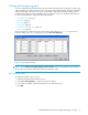


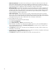

Table Of Contents
- Contents
- About this guide
- Using McDATA Web Server/Element Manager
- Managing Fabrics
- Securing a fabric
- Security consistency checklist
- Connection security
- User account security
- Remote authentication
- Device security
- Edit Security dialog
- Create Security Set dialog
- Create Security Group dialog
- Create Security Group Member dialog
- Editing the security configuration on a switch
- Viewing properties of a security set, group, or member
- Security Config dialog
- Archiving a security configuration to a file
- Activating a security set
- Deactivating a security set
- Configured Security data window
- Active Security data window
- Fabric services
- Rediscovering a fabric
- Displaying the event browser
- Working with device information and nicknames
- Zoning a fabric
- Zoning concepts
- Managing the zoning database
- Managing the active zone set
- Managing zones
- Merging fabrics and zoning
- Securing a fabric
- Managing switches
- Managing user accounts
- Configuring RADIUS servers
- Displaying switch information
- Configuring port threshold alarms
- Paging a switch
- Setting the date/time and enabling NTP client
- Resetting a switch
- Configuring a switch
- Archiving a switch
- Switch binding
- Restoring a switch
- Restoring the factory default configuration
- Downloading a support file
- Installing Product Feature Enablement keys
- Installing firmware
- Displaying hardware status
- Managing ports
- Glossary
- Index
McDATA® 4Gb SAN Switch for HP p-Class BladeSystem user guide 95
Port binding
IMPORTANT: Port binding is available only in Element Manager which requires the Element Manager PFE
key. See ”Installing Product Feature Enablement keys” on page 82 for more information about installing a
PFE key. To obtain the McDATA 4Gb SAN Switch serial number and PFE key, follow the step-by-step
instructions on the firmware feature entitlement request certificate for the PFE key. You can obtain a PFE key
from the web at: www.webkey.external.hp.com
.
Port binding ties one or more device WWNs to a physical port number. The port will accept logins only
from the devices that are on the WWN list. To enable port binding for a port and specify device WWNs:
1. Select a single port on the faceplate display.
2. Select Port > Port Binding to open the Port Binding dialog.
3. Click the Port Binding checkbox to enable port binding.
4. Select each device WWN from the WWN: pull-down menu and click Add. To remove a WWN, select
the WWN in the WWN List and click Remove.
5. Click OK.
Resetting a port
The Reset Port option reinitializes the port using the saved configuration. To reset a port:
1. In the faceplate display, select the ports to be reset.
2. Select Port > Reset Port.
3. Click OK to reset the selected ports.
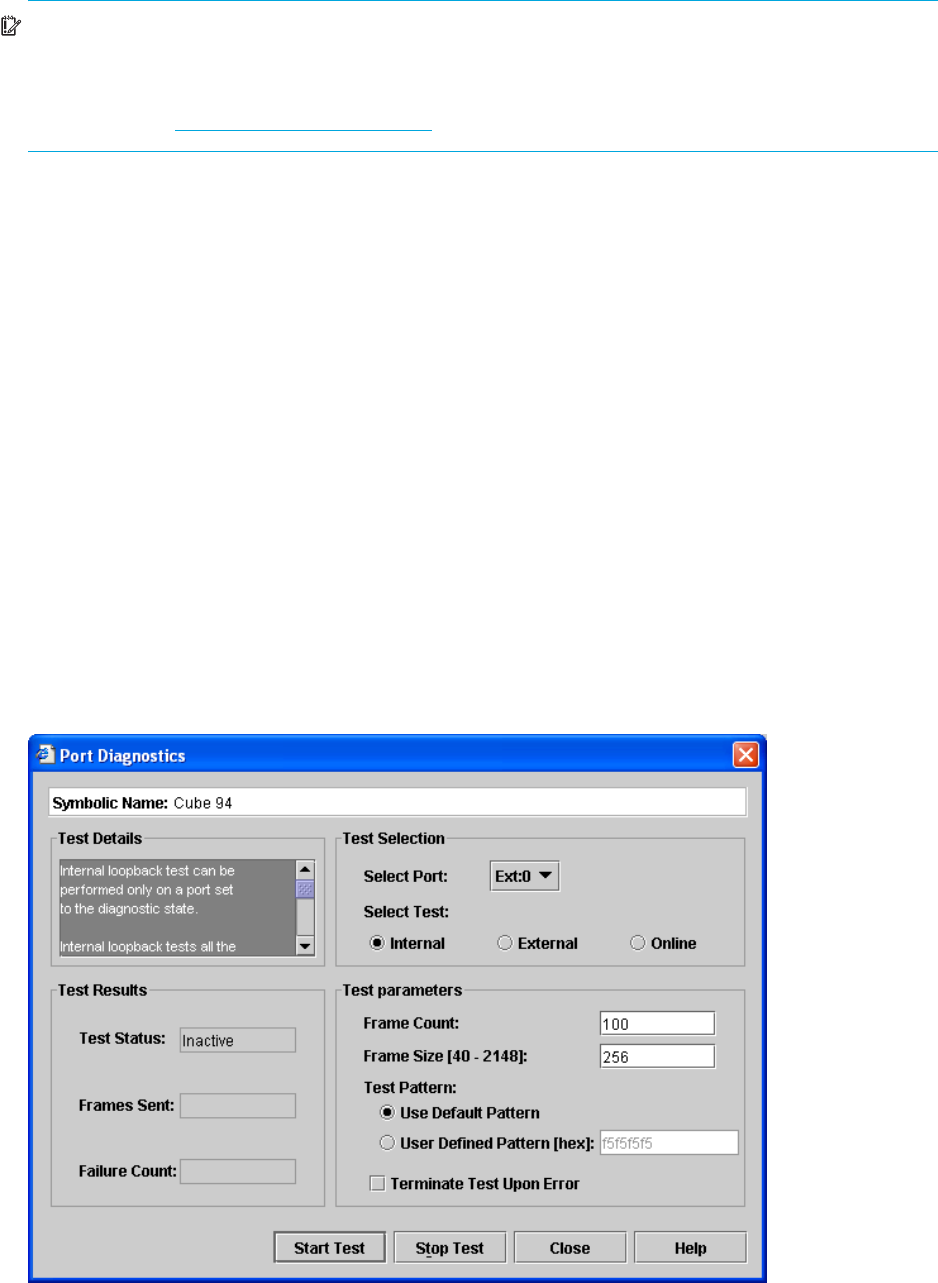
Testing ports
The port diagnostic tests verify correct port operation by sending a frame out through the loop, and then
verifying that the frame received matches the frame that was sent. Only one port can be tested at a time for
each type of test. The Port Diagnostics dialog shown in Figure 42 presents the following loopback tests:
Figure 42 Port Diagnostics dialog