McDATA® 4Gb SAN Switch for HP p-Class BladeSystem user guide Part number: AA-RW20C-TE Third edition: November 2006
Legal and notice information © Copyright 2006 Hewlett-Packard Development Company, L.P. © Copyright 2006 McDATA Corporation. © Copyright 2006. This software includes technology under a license from QLogic Corporation. All rights reserved. Hewlett-Packard Company makes no warranty of any kind with regard to this material, including, but not limited to, the implied warranties of merchantability and fitness for a particular purpose.
Contents About this guide . . . . . . . . . . . . . . . . . . . . . . . . . . . . . . . . . . . . . . . . . . . . . . . . . . . . . 7 Intended audience . . . . . . . . . . . . . . . . . . . . . . . . . . . . . . . . . . . . . . . . . . . . . . . . . . . . . . . . . . Prerequisites. . . . . . . . . . . . . . . . . . . . . . . . . . . . . . . . . . . . . . . . . . . . . . . . . . . . . . . . . . . . . . . Related documentation . . . . . . . . . . . . . . . . . . . . . . . . . . . . . . . . . . . . . . . . . .
Sorting the event browser . . . . . . . . . . . . . . . . . . . . . . . . . . . . . . . . . . . . . . . . . . . . . . . . . . . . . . . Filtering the event browser . . . . . . . . . . . . . . . . . . . . . . . . . . . . . . . . . . . . . . . . . . . . . . . . . . . . . . Saving the event browser to a file . . . . . . . . . . . . . . . . . . . . . . . . . . . . . . . . . . . . . . . . . . . . . . . . . Working with device information and nicknames . . . . . . . . . . . . . . . . . . . . . . . . . . . . . . .
Port status and operational information. . . . . . . . . . . . . . . . . . . . . . . . . . . . . . . . . . . . . . . . . . . . . . McDATA Web Server Configured Zonesets data window . . . . . . . . . . . . . . . . . . . . . . . . . . . . . . . . . Configuring port threshold alarms. . . . . . . . . . . . . . . . . . . . . . . . . . . . . . . . . . . . . . . . . . . . . . . . . . . . Paging a switch . . . . . . . . . . . . . . . . . . . . . . . . . . . . . . . . . . . . . . . . . . . . . . . . . . . . . . . .
10 11 12 13 14 15 16 17 18 19 20 21 22 23 24 25 26 27 28 29 30 31 32 33 34 35 36 37 38 39 40 41 42 Events browser . . . . . . . . . . . . . . . . . . . . . . . . . . . . . . . . . . . . . . . . . . . . . . . . . . . . . . . . . . . . . Filter events dialog. . . . . . . . . . . . . . . . . . . . . . . . . . . . . . . . . . . . . . . . . . . . . . . . . . . . . . . . . . . Devices data window. . . . . . . . . . . . . . . . . . . . . . . . . . . . . . . . . . . . . . . . . . . . . . . . . . . . . . . . .
About this guide This manual describes the McDATA® Web Server™ and McDATA Element Manager™ management tools for the McDATA 4Gb SAN Switch. McDATA Element Manager is referred to as Element Manager throughout this document. The McDATA 4Gb SAN Switch is a 10-port non-blocking Fibre Channel (FC) switch. This manual defines the features, components, and performance characteristics of the McDATA 4Gb SAN Switch.
Document conventions and symbols Table 1 Document conventions Convention Element Medium blue text: Figure 1 Cross-reference links and e-mail addresses Medium blue, underlined text (http://www.hp.
2. Redistributions in binary form must reproduce the above copyright notice, this list of conditions, and the disclaimer that follows these conditions in the documentation and/or other materials provided with the distribution. 3. The name "JDOM" must not be used to endorse or promote products derived from this software without prior written permission. For written permission, please contact license@jdom.org. 4.
Helpful web sites For other product information, see the following HP web sites: • http://www.hp.com • http://www.hp.com/go/storage • http://www.hp.com/support/ • http://www.docs.hp.com • http://h71028.www7.hp.com/enterprise/cache/80316-0-0-0-121.
1 Using McDATA Web Server/Element Manager This section describes how to use the McDATA Web Server and Element Manager applications and their menus. McDATA Web Server is a graphical user interface that provides both fabric and switch module management functions. Because McDATA Web Server resides in the switch firmware, no installation is needed. You can run one instance of the McDATA Web Server at a time by opening the switch IP address with an internet browser.
Workstation requirements The requirements for fabric management workstations running the McDATA Web Server web applet are listed in Table 2. Table 2 Workstation requirements Operating System Microsoft® Windows Server 2000, Windows Server 2003 SP1, Windows XP® Red Hat® Enterprise Linux® 3 and 4 Memory 256 MB or more Processor 500 MHz or faster Hardware RJ-45 Ethernet port, Internet Browser Microsoft Internet Explorer® 5.0 and later Netscape® Navigator® 6.0 and later Mozilla™ 1.
Starting Element Manager in HAFM To use Element Manager, the HAFM client application must be running on your workstation, or you must be accessing HAFM on the HAFM Appliance. See your HAFM documentation for information about starting and using HAFM. To start Element Manager in HAFM, add the switch IP address to the discovery list. Locate and double click the switch in the fabric map to open. You can also select the switch and select Element Manager from the application list.
Setting preferences You can customize the following preference settings for McDATA Web Server and Element Manager: • Change the location of the working directory in which to save files. • Change the location of the browser used to view the online help. • Select a Display Dialog When Making Non-secure Connections option. If enabled, the Non-secure Connections Check dialog is displayed when you attempt to open a non-secure fabric. You then have the option of opening a non-secure fabric.
Using online help Online help is available for the McDATA Web Server and Element Manager applications and their functions. Online help is also context-sensitive, that is, the online help opens to the topic that describes the dialog you have open. To open online help, choose one of the following: • Select Help > Help Topics. • Click Help in dialogs to display context-sensitive help in dialogs.
User interface The McDATA Web Server and Element Manager applications share a common interface as shown in Figure 3. The interface consists of a menu bar, fabric tree, graphic window, data windows (some with buttons), and data window tabs. The switch faceplate is displayed in the graphic window and shows the front of a single switch and its ports. The fabric name is displayed for reference in the fabric tree above the switch names.
Menu bar The McDATA Web Server and Element Manager menu bar options are listed in Table 3.
Table 3 Menu Bar Options (Continued) Menu McDATA Web Server Options Element Manager Options Wizards Configuration Wizard Same as McDATA Web Server Help Help Topics About Same as McDATA Web Server 1. Requires SANtegrity PFE key and Secure Sockets Layer (SSL) enabled. See System services, page 73. Popup menus Popup menus are displayed when you right-click the switch faceplate image in the graphic window.
McDATA Web Server Fabric tree McDATA Web Server enables you to manage McDATA 4Gb SAN Switches and observe other switches in the fabric. The fabric tree, shown in Figure 4, provides access to the faceplate display of each McDATA 4Gb SAN Switch in the fabric, and displays the presence of other switches in the fabric. Click a switch name or icon of a McDATA 4Gb SAN Switch to display that switch faceplate in the graphic window.
Data windows and tabs The data window presents a table of data and statistics associated with the selected tab for the switch displayed in the graphic window. Use the scroll bar to browse through the data. The window length can be adjusted by clicking and dragging the border that it shares with the graphic window. Adjust the column width by moving the pointer over the column heading border shared by two columns until a right/left arrow graphic is displayed. Click and drag the arrow to the desired width.
2 Managing Fabrics This section describes the following tasks that manage fabrics using McDATA Web Server: • Securing a fabric, page 21 • Rediscovering a fabric, page 30 • Displaying the event browser, page 31 • Working with device information and nicknames, page 34 • Zoning a fabric, page 37 Securing a fabric Fabric security consists of the following: • Security consistency checklist, page 21 • Connection security, page 22 • User account security, page 22 • Remote authentication, page 22 • Device securit
Connection security IMPORTANT: The SSL and SSH services can be managed only with Element Manager, which requires the Element Manager PFE key, and the CLI. See ”Installing Product Feature Enablement keys” on page 82 for more information about installing a PFE key. To obtain the McDATA 4Gb SAN Switch serial number and PFE key, follow the step-by-step instructions on the firmware feature entitlement request certificate for the PFE key. You can obtain a PFE key from the web at: www.webkey.external.hp.com.
Device security IMPORTANT: Device security is available only with the McDATA SANtegrity™ Enhanced PFE key and can be managed only with the CLI and Element Manager. Element Manager also requires a PFE key. See ”Installing Product Feature Enablement keys” on page 82 for more information about installing a PFE key. To obtain the McDATA 4Gb SAN Switch serial number and PFE key, follow the step-by-step instructions on the firmware feature entitlement request certificate for the PFE key.
Edit Security dialog Use the Edit Security dialog to edit the security configuration on the switch. You can also open and edit a security configuration saved to a file. Editing security files consists of renaming and removing security sets, groups, and members. The Security dialogs are available only on a secure SSL fabric and on the entry switch (out-of-band switch). To open the Edit Security dialog shown in Figure 5, choose one of the following: • Click Security in the tool bar.
Create Security Set dialog Use the Create Security Set dialog shown in Figure 6 to create a new security set. There is a maximum of 4 security sets. Figure 6 Create Security Set dialog To add a security set from the faceplate display: 1. Click Security on the tool bar, or select Security > Edit Security to open the Edit Security dialog. 2. To open the Create a Security Set dialog, choose one of the following: • Click Security Set in the Edit Security dialog tool bar.
An empty (no members) security group in the active security set will prevent all connections for that security group type. For example, an empty ISL security group will cause the switch to refuse all logins from other switches. To add a security group to a security set: 1. Click Security on the tool bar in the faceplate display or select Security > Edit Security to open the Edit Security dialog. 2.
The conventions for Port security group members are listed below: • You can enter member World Wide Name (WWN), which must be 16 hex characters, or 23 characters with valid WWN format xx:xx:xx:xx:xx:xx:xx:xx. • The authentication choices are None and CHAP. • The Secret field is disabled if authentication is set to None. If authentication is CHAP, the Secret field is enabled. The secondary hash and secret are not supported when connecting to other McDATA products.
Editing the security configuration on a switch To edit a security configuration on the switch from the faceplate display: 1. Choose one of the following to open the Edit Security dialog: • Click Security on the tool bar. • Select Security > Edit Security. By default, the security configuration on the switch is displayed in the Edit Security dialog. 2. Choose one of the following from the Edit Security dialog: • Select File > Open File. Browse for and select the security file. • Press Control+O (letter o).
Security Config dialog Use the Security Config dialog, shown in Figure 9, to save the active security configuration on the switch to non-volatile or to temporary memory, and to require the domain ID of a switch be validated before attaching to the fabric. Figure 9 Security Config dialog To configure switch security from the faceplate display: 1. Select Security > Edit Security Config to open the Security Config dialog. 2. Select the Auto Save option to enable (default) or disable Auto Save mode.
Deactivating a security set Only one security set can be active at one time. To deactivate an active security set from the faceplate display: 1. Select Security > Deactivate Security Set. 2. Select a security set from the drop-down list in the Deactivate Security Set dialog. 3. Click Yes to confirm that you want to deactivate the active security set in the Deactivate Security Set dialog.
Displaying the event browser The Event Browser displays a list of events generated by the switches in the fabric and the McDATA Web Server web applet. Events that are generated by the McDATA Web Server web applet are not saved on the switch, but can be saved to a file during the McDATA Web Server session. To display the Event Browser in McDATA Web Server, choose one of the following: • Select Fabric > Show Event Browser. • Click Events on the tool bar.
Severity is indicated in the severity column using icons as described in Table 4. Table 4 Severity levels Severity Icon Description Alarm — an alarm is a serviceable event. This means that attention by the user or field service is required. Alarms are posted asynchronously to the screen and cannot be turned off. If the alarm denotes that a system error has occurred the customer and/or field representative will generally be directed to provide a support file for the switch.
Filtering the event browser Filtering the Event Browser enables you to display only those events that are of interest based on the event severity, timestamp, source, type, and description. To filter the Event Browser, open the Filter menu and select Filter Entries. This opens the Filter Events dialog shown in Figure 11. The Event Browser displays those events that meet all of the criteria in the Filter Events dialog.
Working with device information and nicknames Devices are hosts and storage targets connected to the switch. A nickname is a user-definable, meaningful name that can be used in place of the World Wide Name. This sub-section describes how to view and manage device information and nicknames.
Displaying detailed device information In addition to the information that is available in the Devices data window, you can click the (i) in the Details column to display more information as shown in Figure 13. Figure 13 Detailed devices display dialog Managing device port nicknames Using McDATA Web Server, you can assign a nickname to a device port World Wide Name. A nickname is a user-definable, meaningful name that can be used in place of the World Wide Name.
Creating a nickname To create a device port nickname: 1. Select Fabric >Nicknames to open the Nicknames dialog. 2. Choose one of the following methods to enter a nickname. A nickname must start with a letter and can have up to 64 characters. Valid characters include alphanumeric characters [aA-zZ][0-9] and special symbols [$ _ - ^ ]. • Double-click a cell in the Nicknames column, and enter a new nickname in the text field. • Click on a device in the table.
Zoning a fabric If HAFM is used to manage the fabric, it is recommended to use HAFM to manage the fabric zoning. If HAFM is not used and other McDATA switch models are in the fabric, it is recommended to use HAFM Basic or EFCM Basic, or in earlier firmware versions, SANpilot or Embedded Web Server to manage the fabric zoning. If all switches in the fabric are McDATA 4Gb SAN switches, use McDATA Web Server to manage the fabric zoning.
Zone sets A zone set is a named group of zones. A zone can be a member of more than one zone set. Each switch in the fabric maintains its own zoning database containing the active zone set. This zoning database resides in non-volatile or permanent memory and is therefore retained after a reset. See ”Displaying the configured and active zone sets” on page 44 for information about displaying the zoning database. The orphan zone set is created automatically to hold the zones that are not in any set.
Zoning limits and properties Zoning limits vary depending on the firmware installed on the switch. To view zoning limits and properties on a switch: 1. Select Zoning > Edit Zoning to open the Edit Zoning dialog. 2. Choose one of the following: • Right-click on the top zonesets entry, a zone set, a zone, or a zone member in the zone sets tree (left windowpane). Select Properties in the popup menu. • Select the top zone sets entry, a zone set, a zone, or a zone member in the zone set tree (left windowpane).
Managing the zoning database Managing the zoning database consists of the following: • Editing the zoning database, page 40 • Configuring the zoning database, page 42 • Saving the zoning database to a file, page 42 • Restoring the zoning database from a file, page 42 • Restoring the default zoning database, page 43 • Removing all zoning definitions, page 43 Editing the zoning database To edit the zoning database for a particular switch, open the Zoning menu and select Edit Zoning to open the Edit Zoning di
• Click a zone, zone set, or port icon. • Right-click to select a zone set or zone, and open the corresponding popup menu. • Hold down the Shift key while clicking several consecutive icons. • Hold down the Control key while clicking several non-consecutive icons. Using tool bar buttons, popup menus, or a drag-and-drop method, you can create and manage zone sets and zones in the zoning database. Table 6 describes the zoning tool bar operations.
Configuring the zoning database Use the Zoning Config dialog to change the Interop Auto Save and Default Zone configuration parameters. The Default Zone parameter applies only when Interop Mode is set to McDATA Fabric Mode. Open the faceplate display. Select Zoning > Edit Zoning Config to open the Zoning Config dialog shown in Figure 15. Click OK after making changes to put the new values into effect.
Restoring the default zoning database Restoring the default zoning clears the switch of all zoning definitions. Restoring default zoning is a fabric-wide action. When you are in Standard mode and restore default zoning, no devices/ports are able to communicate with each other on the switches.
Displaying the configured and active zone sets You can display the contents of the configured zone set and active zone set with the Configured Zoneset data window and the Active Zoneset data window. The Configured Zonesets and Active Zoneset data windows use display conventions for expanding and contracting entries that are similar to the fabric tree. An entry handle located to the left of an entry in the tree indicates that the entry can be expanded.
Creating a zone set To create a zone set: 1. Select Zoning > Edit Zoning to open the Edit Zoning dialog. 2. Select Edit > Create Zone Set to open the Create Zone Set dialog. 3. Enter a name for the new zone set, and click OK. The new zone set name is displayed in the Zone Sets dialog. A zone set name must begin with a letter and be no longer than 64 characters. Valid characters are 0—9, A—Z, a—z, _, -, ^, and $. 4.
Managing zones Managing zones involves the following: • Creating a zone in a zone set, page 46 • Adding zone members, page 47 • Renaming a zone or a zone set, page 47 • Removing a zone member, page 47 • Removing a zone from a zone set, page 48 NOTE: Changes you save to the zoning database on a switch are not propagated to other switches in the fabric unless you activate a zone set or edit the zoning databases on the individual switches in the fabric.
Adding zone members You can zone a port/device by switch domain ID and port number, or the device port WWN. Adding a port/device to a zone affects every zone set in which that zone is a member. Domain ID/port zoning is only supported in McDATA Fabric interop mode for other McDATA switches. To add ports/devices to a zone: 1. Select Zoning > Edit Zoning to open the Edit Zoning dialog. 2.
Removing a zone from a zone set To remove a zone from a zone set: 1. Select the zone to be removed in the Edit Zoning dialog. The selected zone will be removed from that zone set only. 2. Select Edit > Remove. 3. Click Yes in the Remove dialog to save the change. 4. Click Apply in the Edit Zoning dialog to save the change. 5. Click Close to close the Edit Zoning dialog. Zones that are removed from the active zone set are placed in the orphan zone set.
3 Managing switches This section describes the following tasks that manage switches using the McDATA Web Server or Element Manager application.
NOTE: If the same user account exists on a switch and its RADIUS server, that user can login with either password, but the authority and account expiration will always come from the switch database. Creating user accounts A switch can have a maximum of 15 user accounts. To create a new user account on a switch: 1. Select Switch > User Accounts in the faceplate display to open the User Account Administration dialog. 2. Click the Add Account tab to open the Add Account tab page shown in Figure 18. 3.
Removing a user account To remove a user account on a switch: 1. Select Switch > User Accounts in the faceplate display to open the User Account Administration dialog. 2. Click the Remove Account tab to open the Remove Account tab page shown in Figure 19. 3. Select the account (login) name from the list of accounts at the top of the dialog. 4. Click Remove Account. 5. Click Close to close the User Account Administration dialog.
Changing a user account password Any user can change their password for their account, but only the Admin account name can change the password for another user’s account. If the administrator does not know the user’s original password, the administrator must remove the account and add the account. To change the password for an account on a switch: 1. Select Switch > User Accounts in the faceplate display to open the User Account Administration dialog. 2.
Modifying a user account To modify a user account on a switch: 1. Select Switch > User Accounts in the faceplate display to open the User Account Administration dialog. 2. Click the Modify Account tab to open the Modify Account tab page shown in Figure 21. 3. Select the account (login) name from the list of accounts at the top of the dialog. 4. Select the Admin Authority Enabled option to grant admin authority to the account name. 5. Select an Account Expiration Date option.
Configuring RADIUS servers IMPORTANT: RADIUS server support is available only with the McDATA SANtegrity Enhanced PFE key and can be managed only with the CLI and Element Manager. Element Manager also requires a PFE key. See ”Installing Product Feature Enablement keys” on page 82 for more information about installing a PFE key. To obtain the McDATA 4Gb SAN Switch serial number and PFE key, follow the step-by-step instructions on the firmware feature entitlement request certificate for the PFE key.
Adding a RADIUS server A RADIUS server provides a method to centralize user and device authentication over a network. Figure 22 RADIUS Server Information dialog—Add Server tab page To add a RADIUS server: 1. Select Switch > Radius Servers in the faceplate display. The Radius Servers... option will not be available unless the SSL service is enabled. See ”System services” on page 73 for information about enabling the SSL service. 2.
Removing a RADIUS server Removing a RADIUS server, disables the remote authentication of devices or users over the network. Figure 23 RADIUS Server Information dialog—Remove Server tab page To remove a RADIUS server: 1. Select Switch > Radius Servers in the faceplate display. 2. Click the Remove Server tab in the Radius Server Information dialog shown in Figure 23. 3. Select the server to be removed in server list at the top of the dialog. 4. Click Remove Server to remove the server. 5.
Editing RADIUS server information Editing information of a RADIUS server involves changing the configuration of a RADIUS server. Figure 24 RADIUS Server Information dialog—Edit Server tab page To edit information of a RADIUS server: 1. Select Switch > Radius Servers in the faceplate display. 2. Click the Edit Server tab in the Radius Server Information dialog shown in Figure 24. 3. Select the server to be edited in server list at the top of the dialog. 4.
Modifying RADIUS server authentication order Editing information of a RADIUS server involves changing the configuration of a RADIUS server. Figure 25 RADIUS Server Information dialog—Modify Authentication Order tab page To modify the authentication order information of a RADIUS server: 1. Select Switch > Radius Servers in the faceplate display. 2. Click the Modify Authentication Order tab in the Radius Server Information dialog shown in Figure 25. 3.
Displaying switch information The faceplate display and data windows provide the following switch information: • Switch event log, page 59 • Device and Host Bus Adapter information, page 59 • Switch status and operational information, page 60 • Port performance statistics, page 64 • Port status and operational information, page 64 • McDATA Web Server Configured Zonesets data window, page 64 The fabric updates the display by forwarding changes in status to the management workstation as they occur.
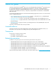
Switch status and operational information The Switch data window, shown in Figure 26, displays the current status and operational information for the selected switch. To open the Switch data window, click the Switch tab below the data window. Figure 26 Switch data window Information in the Switch data window is grouped and accessed by the Summary, Status, Network, User Login, Firmware, Services, Zones/Security, and Advanced buttons.
Table 8 Switch data window entries (Continued) Entry Description Status Operational State Switch operational state: Online, Offline, Diagnostic, Down Administrative State Current switch administrative state Configured Admin State Switch administrative state that is stored in the switch configuration Beacon Status Beacon status. Switch LEDs are blinking (On) or not (off). Reason for Status Additional status information Temperature Internal switch temperature °C Fan 1 Status Not applicable.
Table 8 Switch data window entries (Continued) Entry Description User Login User Name Account name Login Level Authority level Super User Super user privileges enabled/disabled UserAuthentication Enabled Enforcement of account names and authority (always True) Firmware Firmware Version Active firmware version Inactive Firmware Version Not applicable.
Table 8 Switch data window entries (Continued) Entry Description SNMP Enabled SNMP enabled or disabled. Zones/Security Interop Mode Interoperability mode. Use Standard to connect to FC-SW-2 compliant switches and McDATA switches in Open Fabric Mode. Use McDATA Fabric Mode to connect to McDATA switches in McDATA Fabric Mode. The default is Standard. Legacy Address Format Not applicable. Interop Auto Save Zoning auto save status.
Port performance statistics The Port Statistics data window displays port performance data for the selected ports. Click the Port Stats data window tab in the faceplate display to open the Port Statistics data window. See ”Port statistics data window” on page 88 for a description of the Port Statistics data window entries. The Statistics drop-down list is available on the Port Statistics data window, and provides different ways to view detailed port information.
Configuring port threshold alarms IMPORTANT: Port threshold alarms can be managed only with Element Manager, which requires the Element Manager PFE key, and the CLI. See ”Installing Product Feature Enablement keys” on page 82 for more information about installing a PFE key. To obtain the McDATA 4Gb SAN Switch serial number and PFE key, follow the step-by-step instructions on the firmware feature entitlement request certificate for the PFE key. You can obtain a PFE key from the web at: www.webkey.external.
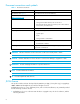
NOTE: The switch will down a port if a rising trigger alarm is not cleared after three consecutive sample windows. Generate rising trigger alarm; eligibility ends Generate rising trigger alarm; eligibility ends Rising trigger Event count Generate falling trigger alarm; eligibility is reset Falling trigger Sample window Figure 29 Port threshold alarm example 8. Enter a sample window in seconds. The sample window defines the period of time in which to count events. 9.
Resetting a switch Resetting a switch reboots the switch using configuration parameters in memory. Depending on the reset type, a switch reset may or may not include a Power-on Self Test (POST), or it may or may not disrupt traffic. Table 9 describes the types of switch resets. During a hot reset operation, fabric services will be unavailable for a short period (30-75 seconds depending on switch model).
Configuring a switch You can configure a switch explicitly or you can use the Configuration Wizard. The Configuration Wizard is a series of dialogs that guide you through the chassis, network, and SNMP configuration steps on new or replacement switches. Select Wizards > Configuration Wizard to launch the Configuration Wizard. Use the Configuration Wizard to configure a new switch in a fabric.
Domain ID and domain ID lock The domain ID is a unique Fibre Channel identifier for the switch. The Fibre Channel address consists of the domain ID, port ID, and the Arbitrated Loop Physical Address (ALPA). Switches come from the factory with the Domain ID Lock setting disabled (False). This means that if there is a domain ID conflict in the fabric, the switch with the highest principal priority, or the principal switch, will reassign any domain ID conflicts and establish the fabric.
Table 10 lists the corresponding domain ID values for each interop mode: Standard mode and McDATA Fabric mode.
Switch administrative states The switch administrative state determines the operational state of the switch. The switch administrative state exists in two forms: the configured administrative state and the current administrative state. • The configured administrative state is the state that is saved in the switch configuration and is preserved across switch resets. McDATA Web Server or Element Manager always makes changes to the configured administrative state.
Fabric Device Management Interface Fabric Device Management Interface (FDMI) provides a means to gather and display device information from the fabric, and allows FDMI capable devices to register certain information with the fabric, if FDMI is enabled. McDATA Web Server or Element Manager will report any and all FDMI information reported by the entry switch, if FDMI is enabled on the entry switch.
Timeout values The switch timeout values determine the timeout values for all ports on the switch. Table 12 describes the switch timeout parameters. The timeout values must be the same for all switches in the fabric. NOTE: Mismatched timeout values will disrupt the fabric. These should not be changed unless absolutely necessary. Therefore, the switch must be offline to change these values. Use the Switch Properties dialog to take the switch offline.
Use caution when disabling the Embedded GUI, GUI Mgmt, Telnet, SSL, and SSH, as it is possible to disable all access to the switch except through a serial connection. IMPORTANT: The SSL and SSH services can be managed only with Element Manager, which requires the Element Manager PFE key, and the CLI. See ”Installing Product Feature Enablement keys” on page 82 for more information about installing a PFE key.
Network properties Use the Network Properties dialog shown in Figure 33 to change IP configuration parameters. To open the Network Properties dialog, choose one of the following: • Select Switch > Network Properties. • Right-click a switch graphic in the faceplate display, and select Network Properties from the popup menu. Click OK to put any new values into effect. Figure 33 Network properties dialog Table 13 describes the IP configuration parameters.
SNMP properties Use the SNMP Properties dialog shown in Figure 34 to change SNMP configuration parameters. After making changes, click the OK button to put the new values into effect. To open the SNMP Properties dialog, choose one of the following: • Select Switch > SNMP Properties. • Right-click a switch graphic in the faceplate display, and select SNMP Properties from the popup menu. Making any changes. Click OK to put the new values into effect.
SNMP configuration The SNMP configuration defines how authentication traps are managed. Table 14 describes the SNMP configuration parameters. The illegal characters for the user-defined fields are the pound sign (#), semi-colon (;), and comma (,). Table 14 SNMP configuration parameters Parameter Description SNMP Enabled Enables or disables SNMP communication with other switches in the fabric.
Archiving a switch You can create an .XML archive file containing the configuration parameters. Basically any data received by McDATA Web Server is archived. This archive file can be used to restore the configuration on the same switch or on a replacement switch. You can also use the archive file as a template for configuring new switches to add to a fabric. Passwords are not archived. Security Group secrets are not included in the archive and must be re-configured using the CLI after a restore.
Restoring a switch Restoring a switch loads the archived switch configuration parameters to the switch. The switch configuration must be archived before it can be restored. The switch archive must be compatible with the switch to be restored; that is, you can restore a McDATA switch only with an archive from a McDATA Web Server switch. See ”Archiving a switch” on page 78 for more information. CAUTION: The switch being restored should be physically disconnected from the fabric.
4. To restore all configuration settings, click the Full Restore tab, then click Restore. To restore selected configuration settings, click the Selective Restore tab and select one or more of the following options, then click Restore: • Network Properties—Restores all settings presented in the Network properties dialog except the IP address. See ”Network properties” on page 75. • IP Address—Restores switch IP address in addition to the other network properties.
Table 16 Factory default configuration settings (Continued) Setting Value FDMI HBA Entry Level 1000 Subnet Mask Address 255.0.0.0 Gateway Address 10.0.0.254 Network Discovery Static Remote Logging False Remote Logging Host Ip Address 10.0.0.254 NTP Client Enabled False NTP Server IP Address 10.0.0.254 Contact Undefined Location Undefined Trap Enabled False Trap Port 162 Trap Address Trap 1: 10.0.0.254; Traps 2-5: 0.0.0.
Installing Product Feature Enablement keys A PFE key is a password that you can purchase from your switch distributor or authorized reseller that enables particular features in your switch. The following PFE keys are available: • SANtegrity Enhanced PFE key enables device security on the switch. This includes support for the following: • RADIUS servers. See ”Configuring RADIUS servers” on page 54. • Device security. See ”Device security” on page 23. • Switch binding. See ”Switch binding” on page 78.
Installing firmware Installing firmware involves loading, unpacking, and activating the firmware image on the switch. McDATA Web Server does this in one operation. To provide consistent performance throughout the fabric, ensure the following: • All McDATA 4Gb SAN Switches are running the same version of firmware. Verify that this version of firmware is compatible with the firmware of other M-series and McDATA switch models in the fabric.
Displaying hardware status To display a summary of the hardware status information in a popup text box, rest the cursor over the chassis LED cluster in the faceplate display. • Power LED—Indicates the voltage status of the switch. • Heartbeat LED—Indicates the general status of the internal switch processor and the results of the POST. • System Fault LED—Indicates an error, such as an over temperature condition, internal system error, voltage fault, or corrupt configuration.
4 Managing ports The data windows provide port information and port statistics for selected ports. This section describes the following tasks that manage ports and devices: • Port information data window, page 85 • Port statistics data window, page 88 • Viewing and configuring ports, page 91 • Port binding, page 95 • Resetting a port, page 95 • Testing ports, page 95 NOTE: External ports are numbered 0 and 9; internal ports are numbered 1–8.
The Port Information data window entries are listed below in Table 17. Table 17 Port information data window entries Entry Description Summary 86 Port Address Port Fibre Channel address. Administrative Port Type The administrative port type (G, GL, F, FL). This value is persistent; it will be maintained during a switch reset. During port auto-configuration, it will be used to determine which operational port states are allowed. Operational Port Type The port type that is currently active.
Table 17 Port information data window entries (Continued) Entry Description Advanced MFS Mode Multiple Frame Sequence bundling status. I/O Stream Guard Not applicable Device Scan Device scan status. Enabled means the switch queries the connected device during login for FC-4 descriptor information. Auto Performance Tuning Enables the switch to dynamically control the MFS_Enable, VI_Enable and LCF_Enable features based on the operational state of the port.
Port statistics data window The Port Statistics data window, shown in Figure 40, displays statistics about port performance. Select one or more ports in the faceplate display that you want to view statistics. Click the Port Stats data window tab to open the Port Statistics window. Figure 40 Port Statistics data window The Statistics drop-down list is available on the Port Statistics data window, and provides different ways to view detailed port information. Click the down arrow to open the drop-down list.
Table 18 Port statistics data window entries (Continued) Entry Description BB_CreditRecoveryFrameFailure Number of times more frames were lost during a credit recovery period than the recovery process could resolve. This causes a Link Reset to recover the credits. BB_CreditRecoveryRRDYFailure Number of times more R_RDYs were lost during a credit recovery period than the recovery process could resolve. This causes a Link Reset to recover the credits.
Table 18 90 Port statistics data window entries (Continued) Entry Description LIP(f7,f7) A loop initialization primitive frame used to acquire an AL_PA. LIP(f8,AL_PS) This LIP denotes a loop failure detected by the L_port identified by AL_PS. LIP(f8,f7) A loop initialization primitive frame used to indicate that a Loop Failure has been detected at its receiver and does not have a valid AL_PA. Login Count Number of device logins that have occurred on the switch.
Viewing and configuring ports Port color and text provide information about the port and its operational state. To display port number and status information for a port, position the cursor over a port on the faceplate display. The status information changes depending on the View menu option selected. Green indicates active; gray indicates inactive. Context-sensitive popup menus are displayed when you right-click a port icon.
Port states The port administrative state determines the operational state of a port. The port administrative state has two forms: the configured administrative state and the current administrative state. Table 19 describes the port administrative and operational states. • The configured administrative state is the state that is saved in the switch configuration and is preserved across switch resets. McDATA Web Server or Element Manager always makes changes to the configured administrative state.
Port types The external ports can be configured to self-discover the proper type to match the device or switch to which it is connected. Table 20 lists the possible port types and their meanings. NOTE: Internal ports can be F_Port or FL_Port only. Port types for internal ports cannot be changed. Select View > View Port Types to display port type status. To change the port type for external ports: 1. Select one or more ports in the faceplate display. 2.
Port speeds External ports are capable of transmitting and receiving at 1-Gbps, 2-Gbps, or 4-Gbps. Internal ports are capable of transmitting and receiving at 1-Gbps or 2-Gbps. The ports can be configured for either transmission speed or to sense the transmission speed of the device to which it is connected. Table 21 lists the possible port speeds. NOTE: The port speed of internal ports is pre-configured and cannot be changed. Select View > View Port Speeds to display the speed of each port.
Port binding IMPORTANT: Port binding is available only in Element Manager which requires the Element Manager PFE key. See ”Installing Product Feature Enablement keys” on page 82 for more information about installing a PFE key. To obtain the McDATA 4Gb SAN Switch serial number and PFE key, follow the step-by-step instructions on the firmware feature entitlement request certificate for the PFE key. You can obtain a PFE key from the web at: www.webkey.external.hp.com.
• SerDes level (internal)—The SerDes level test verifies port circuitry. The SerDes level test sends a test frame from the ASIC through the SerDes chip and back to the ASIC for the selected ports. The port passes the test if the frame that was sent by the ASIC matches the test frame that was received. This test requires that the port be in diagnostics mode, and therefore, disrupts communication. • SFP level (external)—The SFP level test verifies port circuitry.
Glossary Active firmware The firmware image on the switch that is in use Active zone set The zone set that defines the current zoning for the fabric Activity LED A port LED that indicates when frames are entering or leaving the port Administrative state State that determines the operating state of the port, I/O blade, or switch. The configured administrative state is stored in the switch configuration. The configured administrative state can be temporarily overridden using the CLI.
Fabric view file A file containing a set of fabrics that were opened and saved during a previous McDATA Web Server session Fan Fail LED An LED that indicates that a cooling fan in the switch is operating below standard Flash memory Memory on the switch that contains the chassis control firmware Force PROM mode See Maintenance Mode Frame Data unit consisting of a start-of-frame (SOF) delimiter, header, data payload, CRC, and an end-of-frame (EOF) delimiter FRU Field Replaceable Unit HAFM High Av
Principal switch The switch in the fabric that manages domain ID assignments Product Feature Enablement key A password that you can purchase from your switch distributor or authorized reseller to enable particular features in your switch SFP Small Form-Factor Pluggable transceiver Small Form-Factor Pluggable (SFP) A transceiver device, smaller than a GigaBit Interface Converter, that plugs into the Fibre Channel port SNMP Simple Network Management Protocol Target A storage device that responds to
Index A active zone set 38, 44 Active Zoneset data window 44 administrative state configured 71, 92 current 71, 92 port 92 switch 71 alarm configuration 65 archive configuration 78 audience 7 authentication device 54 trap 77 user 54 authorized reseller, HP 9 auto save, zoning 42 B binding, switch 78 BootP boot method 75 broadcast 71 browser 12 browser location 14 C call home 15 certificate 22 checklist 21 Common Information Model 74 configuration archive 78 restore 79 wizard 68 configured administrative s
Fabric Device Management Interface 72 factory defaults 80 FC-4 descriptor 94 FDMI - See Fabric Device Management Interface File Transfer Protocol 74 firmware install with McDATA Web Server 83 non-disruptive activation 83 FL_Port 93 G gateway address 75 generic port 93 graphic window 19 group add member 27 create 26 display 28 display member 28 edit member attributes 28 remove 28 remove member 28 rename 28 GUI management service 74 H HAFM - See High Availability Fabric Manager hard reset 67 hardware status
Q QuickTools 15 R RADIUS - See Remote Authentication Dial-In User Service read community 77 refresh 59 related documentation 7 Remote Authentication Dial-In User Service add server 55 authentication order 58 description 22 edit configuration 57 remove server 56 remote logging 70 reset with POST 67 without POST 67 Resource Allocation Timeout 73 restore configuration 79 Reverse Address Resolution Protocol 75 S scan device 94 Secure Shell description 22 service 74 Secure Socket Layer description 22 service 7
W web server service 74 web sites HP documentation 7 HP storage 10 HP Subscriber’s choice 9 wizard, configuration 68 working directory 14 workstation requirements 12 write community 77 Z zone add member port 47 definition 37 remove member port 47 rename 47 zone merge description 48 failure 48 failure recovery 48 zone set activate 45 active 38, 44 create 45 deactivate 45 definition 38 management 43 orphan 38 remove 45 rename 47 tree 40 zoning 73 configuration 42 database 38, 40 default 43 remove all 43 zoni