HP LTO Ultrium tape drives technical reference manual LTO 4 FC, SCSI and SAS drives volume 2: software integration Edition 1, June 2007 HP restricted
Legal and notice information © Copyright 1999–2007 Hewlett-Packard Development Company, L.P. Hewlett-Packard Company makes no warranty of any kind with regard to this material, including, but not limited to, the implied warranties of merchantability and fitness for a particular purpose. Hewlett-Packard shall not be liable for errors contained herein or for incidental or consequential damages in connection with the furnishing, performance, or use of this material.
Contents Related documents . . . . . . . . . . . . . . . . . . . . . . . . . . . . . . . . . . . . . . . . . . . . . . . . . . . . . . . . . 7 Documents specific to HP Ultrium drives. . . . . . . . . . . . . . . . . . . . . . . . . . . . . . . . . . . . . . 7 Documentation map . . . . . . . . . . . . . . . . . . . . . . . . . . . . . . . . . . . . . . . . . . . . . . . . . . . . . . 7 Drives—general . . . . . . . . . . . . . . . . . . . . . . . . . . . . . . . . . . . . . . . . . . . . . . . . . . . . . .
WORM media . . . . . . . . . . . . . . . . . . . . . . . . . . . . . . . . . . . . . . . . . . . . . . . . . . . . . . . . . . . How WORM media works. . . . . . . . . . . . . . . . . . . . . . . . . . . . . . . . . . . . . . . . . . . . . . Changes to SCSI commands . . . . . . . . . . . . . . . . . . . . . . . . . . . . . . . . . . . . . . . . . . . . Re-writing media labels . . . . . . . . . . . . . . . . . . . . . . . . . . . . . . . . . . . . . . . . . . . . . . . .
Cleaning . . . . . . . . . . . . . . . . . . . . . . . . . . . . . . . . . . . . . . . . . . . . . . . . . . . . . . . . . . Resetting drives . . . . . . . . . . . . . . . . . . . . . . . . . . . . . . . . . . . . . . . . . . . . . . . . . . . . . Further details. . . . . . . . . . . . . . . . . . . . . . . . . . . . . . . . . . . . . . . . . . . . . . . . . . . . . . . Backup software. . . . . . . . . . . . . . . . . . . . . . . . . . . . . . . . . . . . . . . . . . . . . . . . . . . . . . . . . .
HP restricted
Related documents This is one of six volumes that document HP Ultrium drives. This volume provides background information for driver and application developers. The following products are covered: • HP LTO Ultrium 4 full-height SCSI tape drives • HP LTO Ultrium 4 full-height SAS tape drives • HP LTO Ultrium 4 full-height Fibre Channel tape drives NOTE: Throughout this manual frequent reference is made to SCSI commands.
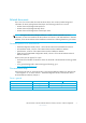
Installation and configuration FC Drives Connectors SCSI Drives 1 HW Integration: ch. 4 SAS Drives 1 HW Integration: ch. 7 Determining the configuration 2 SW Integration: ch. 2 External drives 1 HW Integration: ch. 5 n/a In libraries 1 HW Integration: ch. 1 In servers n/a In tape arrays n/a 1 HW Integration: ch. 4 1 HW Integration: ch. 3 Linux configuration n/a 5 UNIX, Linux, OpenVMS Configuration Modes of usage 1 HW Integration: ch.
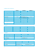
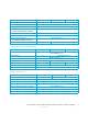
FC Drives SCSI Drives Implementation SAS Drives 3 Host Interface: ch. 1 2 SW Integration: ch. 3 Interpreting sense data Messages 3 Host Interface: ch. 2 Mode pages —see the MODE SENSE command 3 Host Interface: ch. 5 Pre-execution checks 3 Host Interface: ch. 4 Responding to sense keys and ASC/Q 2 SW Integration: ch. 6 Sense keys and ASC/Q —see REQUEST SENSE command 3 Host Interface: ch. 5 Task management functions 3 Host Interface: ch.
LTO Ultrium features FC Drives SCSI Drives Autoload 1 HW Integration: ch. 2 Automation Control Interface (ACI) 1 HW Integration: ch. 2 Cartridge Memory (LTO-CM) 1 HW Integration: ch. 2 2 SW Integration: ch. 5 Data compression, managing 2 SW Integration: ch. 5 OBDR and CD-ROM emulation 2 SW Integration: ch. 7 Performance optimization n/a SAS Drives 1 HW Integration: ch. 8 2 SW Integration: ch. 1 Performance, factors affecting 2 SW Integration: ch. 4 Software design 2 SW Integration: ch.
1 Designing backup applications In today’s computer market, software applications that use tape drives to copy the information from a computer’s hard disk for safe keeping are readily available for many different operating systems. Unfortunately, not all these applications take advantage of the advances made in tape technology over the past few years. This section examines some of the characteristics that a good backup utility should include.
NOTE: Using immediate mode with other commands does not improve performance and can cause problems when writing a driver. The SCSI specification requires that if a command is issued with the IMMEDIATE bit set to 0, the drive must flush its data buffer before it carries out the operation. This takes time. Managing the use of tapes The Ultrium format enables applications to monitor the performance of tapes closely, to indicate when tape heads need cleaning, and when a tape should be discarded.
See “Tape Capacity Log Page” under the LOG SENSE command in Chapter 3 of The SCSI Interface, Volume 3 of the HP LTO Ultrium Technical Reference Manual for more information. While the reliability of tape products and applications is getting better all the time, problems do still occur. There are some very simple techniques that could be incorporated by application developers to simplify the process that a user must go through to resolve problems.
• Use log files to store Inquiry and Sense Key/Error Code information about error conditions. • Allow users to access drive firmware revision and HBA characteristic information • Include the capability to download firmware. • Incorporate simple diagnostic capabilities, such as Write/Read tests and SCSI device discovery. • Incorporate online help.
2 Configuration and initialization This section covers the following topics: • Operating System drivers • Inquiry string recovery, finding information about the drive through the INQUIRY command • Additional LUN support, for operation with an autochanger device • Fibre Channel support Operating system drivers Windows HP have a proprietary driver for Windows 2000 and Windows 2003. It is intended that the driver is freely licensed to any software partner that requires it.
Product ID, first 8 bytes “Ultrium ” This will be the same for all HP Ultrium products, regardless of generation or model.
Since LTO 4 drives cannot write to Ultrium-2 media, the WRTOK bit will be clear for this media type. Support for additional LUN Enabling additional LUN support When enabled by an internally-connected autochanger device, an extra Logical Unit Number (LUN) will be available at the target’s SCSI ID. This allows the attached autochanger device to be addressed via the tape drive. See ”Automation interface” on page 35. For ADI Bridging usage, the automation LUN will usually be LUN1.
Configuration and initialization HP restricted
3 Use of tapes HP Ultrium user documentation and “Cartridges”, Chapter 9 of the Hardware Integration Guide, Volume 1 of the HP LTO Ultrium Technical Reference Manual, also contain information on cartridges. Timing considerations are discussed in “Time-out values” on page 28. LTO cartridge memory NOTE: “Cartridge Memory” is the Ultrium version of the more general term “Media Auxiliary Memory” or MAM, covering all media types.
Tape status and capacity Following autoload or a LOAD command, the software can determine the state of the tape and its capacity from the Cartridge Memory and the Tape Capacity Log pages retrieved through the LOG SENSE command. The information can also be invoked as a console operation at any time to find the status and condition of the media. Tape capacity figures can be used for two purposes: • To give an application or user an indication of whether the tape has enough capacity for a proposed backup.
Capacity calculations are based on estimates; reported values can be subject to error in two ways: • Random errors caused by tolerances in tape length, hub diameter, and so on. • Systematic errors caused by ignoring system areas, and so on. They ensure the calculated capacity is actually available to the user. It is usually possible to write considerably more data than the calculated capacity.
The following table gives the minimum acceptable Capacity Proportion Values and the approximate capacity they will give: Cartridge Min. capacity proportion value Resultant approx. min. capacity Max. capacity Ultrium 2 1605h 17.2 GB 200 GB Ultrium 3 151Ah 33 GB 400 GB Ultrium 4 1055h 51 GB 800 GB NOTE: Capacities are approximate and can be affected by defects that reduce the actual capacity of the tape. Other factors, such as compression and block packing, may also affect capacity.
TapeAlert flags: • 3Bh (WORM medium—integrity check failed) • 3Ch (WORM medium—overwrite attempted) Error Usage page For WORM cartridges, the Wrap Number fields in the Error Usage page are replaced by an Error Code field. This contains the ASC/Q value reported to the host when the associated error was detected.
application to locate the tape in preparation for subsequent writing or reading operations. At the start of an appending archive or backup session, it is common for the application to locate the tape to a logical position immediately preceding the second filemark and to overwrite the second filemark during the data appending session. Writes are allowed: • when the current logical position is at EOD. This means that the drive must have read the EOD from tape before attempting to overwrite it.
Barcode support Ultrium barcode support is required for WORM media so that the application and tape library can distinguish WORM media from normal RW media or cleaning cartridges.
RWW retry counts Data is read immediately after being written to tape to establish that it has been written correctly. Increases in RWW retries can be due to four factors: • Deterioration in the media • Dirty heads • Drive malfunction • The operating environment Corrective action The recommended criteria for corrective action are as follows: RWW Retries > 5% Total data sets written When using tapes without write-protection, use the Total count. The corrective action should be as follows: 1.
4 Factors affecting performance This chapter contains techniques and information to help you design software applications so that they use the tape drive’s potential as efficiently as possible.
absolute block size, performance should not suffer, but do ensure that the transfer size is at least 256 KB. Maximum block size The READ BLOCK LIMITS command indicates that block sizes and variable length transfer sizes are supported for values between 1 byte and 16,777,215 bytes. Media type identification HP recommends that you use the REPORT DENSITY SUPPORT command (with the Media bit enabled) to identify the type of media loaded in the drive.
• All of these values may be subject to change. • There is no retension facility. Recommended support of log pages Some of the media-related data items on the log pages are duplicates of data that is available through the READ ATTRIBUTES command using the Media Auxiliary Memory (MAM) access specification. We recommend that you use MAM commands as the primary source for such data, because this access method is portable to tape drives from other vendors, that is, the data is not in a vendor-unique format.
Performance Factor Detail Example: SCSI: Consider an 8 KB transfer at burst rates of 8 MB/s and 1 MB/s. The fast transfer takes 1 ms, while the slow transfer takes 8 ms. Since the rest of the command may only take 4–5 ms, the difference of 7 ms is very significant. SAS and FC: The SAS link is capable of 3 Gb/s (300 MB/s) whereas the performance of the FC drive depends on the negotiated link speed of the host/HBA port, any intermediate switch ports and the drive port.
Performance Factor Detail Recommendation: • Try not to put Ethernet in the way of data transfer unless staging technology is being used; aggregation of multiple Ethernet clients remains a good strategy to delivering on drive performance. • Even with Gbit Ethernet, the effective throughput is less than that of an LTO Ultrium 4 drive, so either use carefully designed topologies, or stage an image first and use locally attached tape, otherwise the Ethernet itself can become the bottleneck.
Performance Factor Detail Recommendation: A good transfer size to aim at is 256 KB (128 KB minimum). For an application that uses 512-byte records, each fixed-mode transfer should transfer 512 records. Higher transfer sizes are also recommended for higher compression ratios. Variable Mode: Only one block is transferred at a time. The size of the block determines the size of the transfer. Ideally the application should aim to use 256 KB blocks.
HP LTO Ultrium 4 drives technical reference manual, volume 2: software integration HP restricted 33
Factors affecting performance HP restricted
5 Supporting Ultrium features This section covers the following features of HP Ultrium drives: • LTO Cartridge Memory page 35 • Automation and drive interface (ACI and ADI) • Cleaning page 35 page 50 • Resetting drives • Backup software page 50 page 50 • Controlling data compression • Other Mode page information page 51 page 51 Cartridge Memory (LTO-CM) LTO Cartridge Memory (LTO-CM) is EEPROM memory that is embedded in every LTO Ultrium tape cartridge.
Automation/Device Interface (ADI) There are two elements to the Automation/Device Interface (ADI): • ADI Transport Protocol (ADT)—a standard protocol for communication between a SCSI automation device and a SCSI data transfer device, such as a tape drive. The ADT protocol allows conforming ADI SCSI devices to inter-operate. The objectives of ADT are: • To provide a low-cost interconnect method between an automation device and the data transfer devices that reside within the media changer.
Automation Control Interface (ACI) The Automation Control Interface (ACI) protocol allows the activities of the drive to be coordinated within a library. The protocol has been designed so that it can be made into a standard feature of tape drives. It provides a rich and extensible functionality to allow automation manufactures to add value in their application of it.
cartridge at the moment that the drive starts to pull it into the drive, if it is configured for that type of operation. This degree of control over synchronization cannot be achieved though the host’s backup software; it must be controlled directly by the library controller. Most tape libraries work this way today. The process is transparent to the backup software.
• Send SCSI with the following opcodes: Log Select Mode Sense Read Attribute Mode Select Request Sense Write Attribute New features in ACI 4.3 The following sections describe the differences between revision 4.2 of the ACI specification, used in HP LTO Ultrium 3 drives, and revision 4.3, used in HP LTO Ultrium 4 tape drives. The main additions to ACI 4.2 revision are: • Improved backward compatibility • Support for encryption Backward compatibility To provide backward compatibility with ACI 4.
• If the drive receives a valid ACI 4.1 format Set Drive Configuration command. • An ACI 4.2 or ACI 4.3 format Set Drive Configuration command with the ACI Major/Minor Version fields set to 41h. • The tape drive is reset. Fibre Channel tape drives do not support ACI 4.0 compatibility mode, so they will only accept ACI version 4.1 and later commands. • An SAS tape drive will remain in ACI 4.2 compatibility mode until it receives a valid ACI 4.2/4.
SCSI command Supported during initialization REQUEST SENSE Yes REPORT DENSITY REPORT No REPORT LUNS Yes SEND DIAGNOSTIC No TEST UNIT READY Yes WRITE ATTRIBUTE No When the drive has completed the second step of initialization, it will respond normally to all supported commands, and it will report the correct Manufacturing Date Code and Serial Number in the corresponding fields of the Get Drive Info RDATA.
7 6 5 4 Reserved 5 3 2 1 Encryption Status 0 WORM The Encryption Status bits indicate the current encryption/decryption status of the SSC device server: Value 00b 01b 10b, 11b Meaning The device server is currently not performing encrypting or decrypting operations. The device server is currently performing encrypting or decrypting operations. Reserved. Further details For more information about ACI, see the ACI Specification supplied by HP.
Table 1 Non-queued ACI commands ACI Command Recommended time-out value Get Drive Info 5s Get Drive Status 5s Get Drive Configuration 5s Get Error Info 5s Get Buffer Size 5s No Op 5s Acknowledge Attention 5s Table 2 Queued ACI commands ACI Command Recommended time-out value ACI Load—immediate ACI Load—non-immediate (drive idle, unloaded) ACI Unload—immediate 5s 300s 5s ACI Unload—non-immediate (tape loaded, at EOM, drive idle) 300s or 9000s depending on implementation strategy Set D
During the second step of the power-up sequence, the tape drive will respond with BUSY status to all ACI commands except Get Drive Info and Get Error Info.
HP recommends configuration of the upgrade protect features to enabled. (the Upgrade Protect bit of the Set Drive Configuration command is set to 1). This will ensure that if a firmware upgrade cartridge is loaded inadvertently, the drive’s micro-code will not be upgraded unnecessarily. If requested, HP will alter the default settings for Auto-Eject, Auto-Load, Auto-Thread, Clean Protect, and Upgrade Protect features in your particular variant of the firmware.
process and that the normal power-up ACI command sequence is followed to ensure that the drive is configured correctly and to verify the firmware version and ACI version. Firmware upgrade via the primary host interface The library controller will not have direct visibility if a firmware upgrade of the tape drive is initiated via SCSI, hence it is recommended that the controller monitors for the that a firmware upgrade is taking place or has taken place.
Cleaning cartridge (HP-configured or Universal) When a valid cleaning cartridge (one that has not expired) is loaded, behavior depends on the Clean Protect bit of the Set Drive Configuration command. Clean Protect = 1 f the Clean Protect bit is set to 1, the drive will not thread the tape or clean the drive until an ACI Load command with the Clean bit set to 1 is sent to the drive. If the Load command is sent without the Clean bit set the drive will return a CHECK CONDITION.
Data cartridge with unreadable CM If the Cartridge Memory cannot be read, the drive assumes that the cartridge is not supported. If the cartridge is loaded into the drive, it will be placed at the ready-to-eject point with the Cartridge Present, Write Protect, Ready Eject, Ready Load, Media Error, and TapeAlert bits set to 1, Cartridge Type = ‘Unknown’, and Tape Activity = ‘Idle’. TapeAlert flag 0Fh will be set.
Invalid firmware upgrade cartridge If a firmware upgrade cartridge with an invalid firmware image is loaded, and neither the library controller nor the host knows that the cartridge is a firmware upgrade cartridge, again what occurs depends on the Upgrade Protect bit in the Set Drive Configuration command.
Resetting drives The tape drive can be reset by the automation controller via the ACI Reset command or, in ACI mode, by pulling the ACI_RST_L line low (see “Rear Panel and Connectors”, Chapter 7 of the Hardware Integration Guide, Volume 1 of the HP LTO Ultrium Technical Reference Manual). Resetting via the ACI Reset command Two levels of reset via the Automation Interface are provided, namely ACI Reset and Drive Reset.
LTO 4 SAS drive “HP Ultrium 4-SCSI” (“SCSI” is not a typo!) LTO 4 FC drive “HP Ultrium 4-SCSI” (“SCSI” is not a typo!) Controlling data compression The data compression hardware in HP Ultrium drives can detect whether incoming data is already compressed and will not attempt to compress it again. The drive can switch dynamically and automatically between compressing and non-compressing modes, thereby optimizing both compression ratio performance and data rate.
Write delay time The Write Delay Time field (bytes 6–7) on the Device Configuration mode page (10h) specifies the inactivity delay before the drive will automatically flush its data buffer. A value of 0 is an infinite delay; any other value is the delay in 100ms units. This parameter is modifiable by a MODE SELECT command. The default value is 12Ch (300d) which corresponds to 30s.
6 Sense keys and codes Sense keys—actions to take Ultrium drives follow the ANSI definition of sense keys. The following table explains how the drives interpret sense key descriptions. As sense keys and additional sense codes are intended to be hierarchical errors, the table recommends action for the host when a particular sense key is reported. For more detailed recovery actions, see “Additional sense codes—actions to take” on page 57.
Code Sense Key Interpretation This sense key generally means the host will have to wait for the drive to become READY. Media access is not possible. See “3h—MEDIUM ERROR” on page 62. Also see the Media Access pre-execution check. 2h NOT READY Action: The host needs to take one of the following actions: • Wait until the drive becomes available. • Issue some type of initializing command. • Perhaps instruct the user to put the drive online.
Code Sense Key Interpretation This indicates that the current I/O operation has failed due to a hardware failure.The FRU code in the sense data should indicate which part of the hardware is bad. The drive should not be used again until corrective action has been taken. Specific recovery depends on the operating system and application. 4h HW ERROR For additional sense codes, see “4h—HW ERROR” on page 67.
Code Sense Key Interpretation 7h DATA PROTECTION This is an error if the I/O operation is attempting to access the media in some manner and failing because data on the media may not be accessed at this time (for example, because the tape is write-protected; or the drive is unable to decrypt data because the key is incorrect). For additional sense codes, see “7h—DATA PROTECTION” on page 72. Also see the Media Write pre-execution check. Action: Depends on the operating system.
Code Sense Key Dh VOLUME OVERFLOW Interpretation Data could not be written because of a lack of remaining space on the tape. See the WRITE and WRITE FILEMARK commands. Recovery from this depends on the device class and the operating system. It is a “generic” sense key—the host should be able to recover from it without knowing the additional sense code. For additional sense codes, see “Dh—VOLUME OVERFLOW” on page 76.
0h—NO SENSE The following action applies to most additional sense codes in this group: Action: For all additional sense codes except 82 82h, the action of the software depends on the current I/O and what the operating system has been expecting. Recovery depends on the operating system. As a minimum, the software should pass an error to the calling application indicating the positional mark that has been encountered. The I/O can be retried if desired.
1h—RECOVERED ERROR NOTE: Reporting of recovered errors defaults to OFF. Action: In all cases, action depends on the device class and operating system. Code Meaning Comments 37 00 Rounded parameter The drive needs to round off the value of a parameter sent by MODE SELECT because it cannot store it to the degree of accuracy sent by the command. 5D 00 Failure prediction threshold Failure Prediction thresholds have been exceeded exceeded indicating that TapeAlert flags have been activated.
Code Meaning Comments 04 01 LUN in process of becoming ready A media access command has been received while a load is occurring with immediate report on, or initiated through the front panel, or a different host initiated the command. Action: 1. Effectively poll the drive by re-sending the command until the media is loaded, when UNIT ATTENTION with additional sense of 28 00h will be set if the tape was inserted via the front panel. Otherwise poll the drive (TUR) until GOOD status is reported.
Code Meaning Comments 30 03 Cleaning cartridge installed. A medium-access command has been sent to the drive while a cleaning cartridge was loaded. Action: 1. Terminate the current I/O, and return the appropriate error. 2. Send a message to the console indicating that a cleaning cartridge is in the drive and a cleaning cycle is being performed. 3. Prompt the user to wait for the cartridge to be ejected. In a library, the cartridge will be ejected when requested by the library or host.
3h—MEDIUM ERROR Code Meaning Comments 00 02 End of Tape detected A READ, SPACE, WRITE or WRITE FILEMARKS command found EOT unexpectedly. This typically occurs when a drive cannot locate the target object on tape because the block count is too great.The EOM flag will be set. Action: 1. Recovery action depends on the initiating action. As a minimum, tell the calling application that physical EOP/M has been encountered. Also display this information as a console message. 2.
Code Meaning Comments 11 00 Unrecovered read error A read from tape has failed. This is probably due to bad media, but may be hardware-related. Action: 1. Terminate the current I/O and return the appropriate error. 2. Send a console message that an unrecovered error on write has occurred. 3. Determine whether the error is deferred, and report the last successful operation and the failed operation to the calling application. 4. Log the error and all recovery actions in the system log.
Code Meaning Comments 14 03 End of data not found A read-type operation failed because a format violation related to a missing EOD data set, or there was an attempt to read a brand new tape. Action: 1. Terminate the I/O and return the appropriate error. 2. Send a message to the console indicating that EOD could not be found because the tape has a corrupt format. 3. Prompt the user to back up the data to another tape and discard the current one. 4. Log the incident in the system log.
Code Meaning 30 07 Cleaning failure Comments A cleaning operation was attempted but could not be completed for some reason. Action: Use another cleaning cartridge because the current one has expired. 30 0D WORM medium—integrity The drive has detected an inconsistency when performing check failed an integrity check on a WORM cartridge. The cartridge may have been tampered with. Data can be read from the cartridge by setting the WTRE bit in the Device Configuration mode page.
Code Meaning Comments 3B 00 Sequential positioning error The drive has failed to read data off tape. There are two possibilities: • The current command (such as READ, SPACE, REWIND, or WRITE) failed to complete successfully. • The logical position has been lost. Action: 1. Attempt to recover by executing a REWIND command to return to a known position such as BOT. 2. Space to the position of the last known successful command and retry the failing command. 3.
Code Meaning Comments 53 00 Media load or eject failed A load or eject has failed. Action: 1. Terminate the current I/O and return the appropriate error. 2. Inform the user that a serious fault has been detected with the tape cartridge. 3. Advise the user to discard this cartridge and select a new one. 4. Log the incident in the system log. 53 04 Medium thread or unthread failure The threading or unthreading operation failed. Action: 1. Terminate the current I/O and return the appropriate error. 2.
Code Meaning Comments 53 01 Unload tape failure The tape unload failed because it cannot be physically completed at this point in time. Action: see above 82 83 Bad microcode detected The data transferred to the drive during a firmware upgrade is corrupt or incompatible with the drive hardware. Action: see above 5h—ILLEGAL REQUEST The following actions apply to all additional sense codes in this group: Action: 1. Terminate the current I/O and return the appropriate error. 2.
Code Meaning Comments 26 04 Invalid release of persistent The Persistent Reservation holder has tried to release the reservation persistent reservation using the PERSISTENT RESERVE OUT command, but the Scope or Type supplied was invalid. 2C 00 Command sequence invalid The sequence of SCSI commands is invalid. Example 1: The use of the echo buffer was invalid. A WRITE BUFFER command is necessary before a READ BUFFER command. Example 2: Another initiator has already started a firmware download process.
Code Meaning Comments 29 01 Power-on reset The drive has powered on since the host last accessed it. Action: 1. The action of the calling application depends on the current I/O and what the operating system is expecting. 2. For parallel SCSI, the host should renegotiate transfer parameters, and reconfigure the drive with any host-specific operating parameters (burst size, bus activity limit, fixed or variable mode, and so on). 3. The host should then report to the console that the drive has been reset.
Code Meaning Comments Action: When operating the drive in this type of environment, the following actions should occur: 1. The calling application receiving this code should issue a MODE SENSE command requesting the drive to return all parameters. 2. The application should check those parameters over which it has configuration control, to ensure that the current configuration of the drive does not conflict with what the application expects. 3.
7h—DATA PROTECTION Code Meaning Comments 26 10 Data decryption key fail limit reached A SECURITY PROTOCOL OUT command has failed because an incorrect key has been sent to the drive followed by a read, and this has happened ten times consecutively. Action: Further SECURITY PROTOCOL OUT commands will not succeed until one of these actions has been taken: • Unload and reload the current tape. • Power-cycle the drive.
Code Meaning Comments 30 0C WORM—overwrite attempted A write operation could not be executed because an overwrite has been attempted on a WORM cartridge. This may be because an overwrite backup was specified instead of an appended backup. Action: 1. Terminate the I/O and return the appropriate error. 2. Send a message to the console indicating that an attempt has been made to overwrite on a WORM cartridge. 3. Prompt the user to either use a new cartridge or change the operation to an appended backup. 4.
Code Meaning Comments 74 03 Incorrect data encryption key The drive read into a block of data which could not be decrypted with the current decryption key. Action: 1. Send a SECURITY PROTOCOL IN with the page set to Next Block Encryption Status to obtain information about the next block on tape. 2.
Code Meaning Comments 14 03 End of Data not found A read-type operation failed because a format violation related to a missing EOD data set. The most likely cause is a tape with corrupt format (perhaps from a powerfail when the tape was being written). Action: 1. Terminate the current I/O and return the appropriate error. 2. Send a message to the console indicating that EOD could not be found because the tape has corrupt format. 3.
Code Meaning 4E 00 Overlapped commands attempted Comments A host has selected the drive even though it already has a command outstanding. 74 08 Digital signature validation The SCSI command used to download the new firmware failure image failed because the firmware image digital signature could not be correctly validated. Dh—VOLUME OVERFLOW Code Meaning Comments 00 02 End of Tape detected A WRITE or WRITE FILEMARKS command has encountered EOT or the physical end of tape. The EOM flag will be set.
7 Exception handling These pages cover methods of dealing with certain error conditions and exceptional circumstances.
5. Parallel SCSI only: Allow the System Supervisor or support person to perform a controlled hard SCSI Bus Reset. If the LOGICAL UNIT RESET Task Management function fails to clear the problem, the System Supervisor or technical support person should be able to perform a controlled hard SCSI Bus Reset as follows: • Lock other users out cleanly. • Go to a minimal-system single-user mode. • Close all applications. • Execute a hard SCSI Bus Reset.
Flags The following table lists the flags that could potentially be supported in tape drives. Of these, flags 3,4,5,6,20,22 and 31 are mandatory for drives such as Ultrium drives that support cleaning cartridges.
Flag 4 Media Type Set Recommended Host Message C Your data is at risk: 1. Copy any data you require from this tape. 2. Do not use this tape again. 3. Restart the operation with a different tape. 5 Read failure 6 Write failure C C The tape is damaged or the drive is faulty. Call the tape supplier’s helpline. Cause Media performance is severely degraded or the tape can no longer be written or read. This flag is set for any unrecoverable read/write/positioning error caused by faulty media.
Flag Type Set Recommended Host Message 10 No removal I You cannot eject the cartridge because the tape drive is in use. Wait until the operation is complete before ejecting the cartridge. Cause A manual or software unload was attempted when Prevent Medium Removal was in force.
Flag 19 Nearing media life Type Set Recommended Host Message I Cause The tape cartridge is nearing the end The tape may have of its calculated life. It is recommended that you: exceeded its specified number of passes. 1. Use another tape cartridge for your next backup. 2. Store this tape cartridge in a safe place in case you need to restore data from it. Flags for Cleaning Management 20 Clean now C The tape drive needs cleaning: The tape drive has detected that it needs cleaning.
Flag Type Set Recommended Host Message Cause 24 Retension requested W The tape drive has requested a retension operation. The drive is having trouble reading or writing that will be resolved by a retension cycle. 25 Dual-port interface error W A redundant interface port on the tape drive has failed. One of the interface ports in a dual-port configuration (in other words, Fibre Channel) has failed. Flags for Tape Drive Hardware Errors 26 Cooling fan failure W A tape drive cooling fan has failed.
Flag 32 Interface Type Set Recommended Host Message W The tape drive has a problem with the application client interface: Cause The drive has identified an interface fault. 1. Check the cables and cable connections. 2. Restart the operation. 33 Eject media C The operation has failed: Error recovery action. 1. Eject the tape or magazine. 2. Insert the tape or magazine again. 3. Restart the operation.
Flag Type Set Recommended Host Message 51 Tape directory invalid at unload W 52 Tape system area write failure C Cause The tape directory on the tape An error has occurred preventing the tape directory cartridge just unloaded has been corrupted. File search performance being updated on unload. will be degraded. The tape directory can be rebuilt by reading all the data. The tape just unloaded could not write its system area successfully: 1. Copy the data to another tape cartridge.
Flag 57 Automation interface failure Type Set Recommended Host Message C The tape drive has a problem with the automation interface: 1. Check the power to the automation system. Cause The drive has identified a fault in the automation interface. 2. Check the cables and cable connections. 3. Call the supplier’s helpline if the problem persists. 58 Firmware failure W The tape drive has reset itself due to There is a firmware bug.
NOTE: Once cleared, a flag cannot be set again until the specified clearing conditions are met. So, for example, if the cartridge in the drive is not of data grade, once flag 8 has been cleared, it cannot be set again until the cartridge has been removed. Designing software to use the TapeAlert log When writing software to take advantage of the ability of a drive to predict problems and actions that a user should take, it is important not to exclude drives that do not support this feature.
In addition, the application can determine which TapeAlert flags are supported by the device server through the TapeAlert supported flags VPD page (B2h). TapeAlert polling usage model In this model, the application configures the device server by setting the TASER bit in the Device Configuration Extension mode page (10h) to one. The device server does not notify the application that a TapeAlert flag has changed.
5. Optionally, automate the recommended recovery actions if there are multiple tape drives or autoloaders present. For example, the application could perform a cleaning cycle in response to flags 20 (Clean Now) and 21 (Clean Periodic). It could perform a tape copy for flags 4 (Media performance degraded) and 7 (Media life expired), and then retire the suspect tape cartridge. This provides an opportunity for applications to add value to the TapeAlert capability of the drives.
1. Clean the heads and try the operation again. 2. If the ‘Clean’ LED is lit again, repeat the operation with another tape cartridge. If this clears the ‘Clean’ LED, it indicates that the original cartridge is at fault. Copy the data from the cartridge onto a new one and discard the old cartridge. The ‘Clean’ LED is cleared by a cleaning cycle.
Glossary ANSI American National Standards Institute, which sets standards for, amongst other things, SCSI and the safety of electrical devices. BOM Beginning Of Media. The first point on the tape that can be accessed by the drive. buffered mode A mode of data transfer in write operations that facilitates tape streaming. It is selected by setting the Buffered Mode Field to 1 or 2 in the SCSI MODE SELECT Parameter List header.
offline The drive is offline if the tape is currently unloaded or not in the drive. The host has limited access, and cannot perform any commands that would cause tape motion. The host can, however, load a tape, if one is inserted, and can execute any diagnostic tests that do not require tape motion. online The drive is online when a tape is loaded. The host has access to all command operations, including those that access the tape, set configurations and run diagnostic tests.
Index A ACI 17, 35, 37 cleaning 49 command set 38 commands that affect streaming 38 firmware upgrade 46 protocol communications retry 45 reserved fields 43 resetting drives 50 supporting 42 ACI 4.
EOM 58, 62, 91 EOPD 22 EOT 76 errors hard 91 parity 75 read 63 write 62, 66 escalation procedure 77 EW-EOM 91 exception handling 77 F faults, predicting 13, 78 filemarks 91 detected 58 use of 32 firmware revision 13 firmware upgrade 45, 48 loading an invalid cartridge 49 fixed-length block mode 11 flags, TapeAlert 79 format, corrupt 65 front panel LEDs 89 FRU 91 G generation, finding 16 H hard error 91 host 91 I identifying tape cartridge types 19 INCITS 10 initialization 15 INQUIRY command 13 inquiry s
P T parity error 75 partition size 52 pass-through mode 38, 90 performance factors 27 drive-related 31 format-related 32 host-related 29 performance log 28 polling frequency, Get Drive Status 45 power-up sequence 43 problems, predicting 13, 78 product ID 15 product revision level 15, 16 Tape Capacity log 20 tape heads, cleaning 12 tape integrity 24 TapeAlert informational exception usage model 88 polling usage model 88 TapeAlert log 13, 25, 78, 92 reading 88 using 87 tapemarks, use of 32 tapes capacity 2
HP restricted