
User Guide

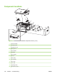
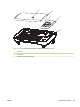


Component locations
1
2
4
3
5
6
7
11
13
14
12
5
10
9
5
5
8
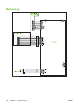
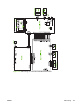
Figure 7-11 HP LaserJet M1005 MFP component locations (1 of 2)
1 Scanner assembly
2 Assembly link, left
3 Assembly link, right
4 Spring, pop-up
5 Screw, M3X0.5
6 ESD shield
7 Screw, M3X0.5
8 Plate, I/O
9 Shield, safety
10 PCA, formatter
11 Printer base
12 Cover, right
13 Output support bin
14 Main input tray (tray 1)
148 Chapter 7 Troubleshooting ENWW