
User Guide


Fuser
1. Remove the following assemblies.
●
Scanner assembly. See
Scanner assembly on page 67.
●
Left cover. See
Device side covers on page 82.
●
Rear cover and fuser cover. See
Rear cover and fuser cover on page 86.
●
Print cartridge door. See
Print-cartridge door on page 85.
●
Front cover. See
Front cover on page 88.
●
Scanner support frame and chassis reinforcement plate. See
Scanner support frame
on page 95.
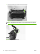
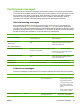
2. Disconnect cables from near the top of the engine power assembly and disconnect the large
grounding wire from the back of the device.
3. Disengage the wire-harnesses from the wire retainers to release the fuser assembly.
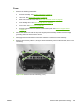
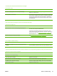
4. Remove three screws (callout 1; this figure shows the delivery-sensor PCB removed, which is not
necessary).
Figure 6-65 Remove the fuser assembly (1 of 2)
ENWW Removal and replacement strategy 105