
User Guide


Laser/scanner assembly
1. Remove the following assemblies.
●
Scanner assembly. See
Scanner assembly on page 67.
●
Left cover. See
Device side covers on page 82.
●
Rear cover and fuser cover. See
Rear cover and fuser cover on page 86.
●
Print cartridge door. See
Print-cartridge door on page 85.
●
Front cover. See
Front cover on page 88.
●
Scanner support frame. See
Scanner support frame on page 95.
●
ECU. See
Engine controller unit on page 98.
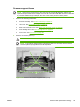
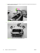
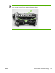
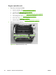
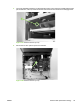
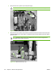
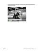
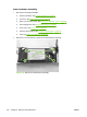
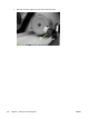
2. Remove four screws (callout 1). Remove the laser/scanner assembly.
Figure 6-62 Remove the laser/scanner assembly
102 Chapter 6 Removal and replacement ENWW