
User Manual

2-13
Installing the Series 4100GL Switches
Installation Procedures
Installing the Series 4100GL
Switches
The port LEDs on the switch modules go into their normal operational
mode:
• If the ports are connected to active network devices, the Link LEDs
stay on and the Mode LEDs behave according to the mode selected.
In the default mode (Activity), the Mode LEDs should flicker showing
network activity on the port.
• For the ports that are not connected to active network devices, the
LEDs will stay off.
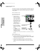
5. Mount the Switch
After the modules and optional power supply are installed and you have
verified that the switch passes self test, you are ready to mount the switch in
a stable location. The Series 4100GL Switches can be mounted in these ways:
in a rack or cabinet
on a horizontal surface
on a wall
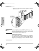
Rack or Cabinet Mounting
The Series 4100GL Switches are designed to be mounted in any EIA-standard
19-inch telco rack or in an equipment cabinet such as a server cabinet. If you
are installing the switch in an equipment cabinet, please see the “Equipment
Cabinet Note” on page 2-16.
Caution For safe operation, please read the mounting precautions on page 2-3 before
mounting the switch.
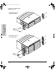
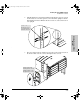
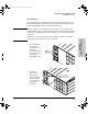
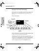
1. Use a #1 Phillips (cross-head) screwdriver and attach the mounting
brackets to the switch with the included 10-mm M4 screws.
For the 4-slot Switch 4104GL and Switch 4148GL, each bracket is attached
with two screws, and for the 8-slot Switch 4108GL and Switch 4108GL
Bundle, each bracket is attached with three screws as shown in the
illustrations on the next page.
stingray.book Page 13 Sunday, March 24, 2002 1:54 AM