
User Manual

2-6
Installing the Series 4100GL Switches
Installation Procedures
Installing the Series 4100GL
Switches
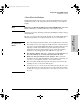
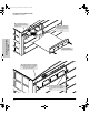
Installation Location
Before installing the switch, plan its location and orientation relative to other
devices and equipment:
In the front of the switch, allow at least 7.6 cm (3 inches) of space for the
twisted-pair and fiber-optic cabling.
In the back of the switch, allow at least 10.2 cm (4 inches) of space for the
power cord and cooling.
On the sides of the switch, leave at least 7.6 cm (3 inches) for cooling.
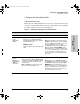
Fiber Optic Cables
100Base-FX
(on the 100-FX
Transceiver)
62.5/125 mm or 50/125 mm (core/cladding)
diameter, graded-index, multimode fiber-optic
cables that are fitted with SC connectors
• 2 kilometers for full-duplex connections
Gigabit-SX
(on the
Gigabit-SX
Transceiver and
Gigabit-SX
mini-GBIC)
62.5/125 mm or 50/125 mm (core/cladding)
diameter, low metal content, graded-index,
multimode fiber-optic cables that are fitted
with SC connectors
• 62.5 mm cable:
– 160 MHz*km = 220 meters
– 200 MHz*km = 275 meters
• 50 mm cable:
– 400 MHz*km = 500 meters
– 500 MHz*km = 550 meters
Gigabit-LX
(on the
Gigabit-LX
Transceiver and
Gigabit-LX
mini-GBIC)
9/125 mm (core/cladding) diameter, 1310 nm,
low metal content, single-mode fiber-optic
cables fitted with SC or LC connectors,
depending on the module and transceiver or
mini-GBIC used.
The multimode cables listed for Gigabit-SX
may also be used, but a mode conditioning
patch cord may be needed — see the
Installation Guide that came with the module
for more information.
• single-mode cable - 10 kilometers
• multimode cable - 550 meters
Port Type Cable Type Length Limits
stingray.book Page 6 Sunday, March 24, 2002 1:54 AM