
Specifications


Thermal/Mechanical Design Guide 39
ATX Reference Thermal Solution
6 ATX Reference Thermal
Solution
Note: The reference thermal mechanical solution information shown in this document
represents the current state of the data and may be subject to modification.The
information represents design targets, not commitments by Intel.
The design strategy is to use the design concepts from the prior Intel® Radial Curved
Bifurcated Fin Heatsink Reference Design (Intel® RCBFH Reference Design) designed
originally for the Intel® Pentium® 4 processors.
This chapter describes the overall requirements for the ATX heatsink reference thermal
solution including critical-to-function dimensions, operating environment, and
validation criteria.
6.1 Operating Environment
Table 6-1 provides the target heatsink performance for the ATX heatsink reference
thermal solution supporting the processor at several system and ambient conditions.
The exhaust air flow from the processor thermal solution is the inlet air flow to the IOH
reference thermal solution and other components such as the voltage regulator. This
airstream is assumed to be approaching the IOH heatsink at a 30° angle from the
processor thermal solution, see the Intel
®
X58 Express Chipset Thermal and
Mechanical Design Guide for more details.
Table 6-1 summarizes the boundary conditions for designing and evaluating the
processor thermal solution. In addition to the power dissipation a set of three system
level boundary conditions for the local ambient T
A
and external ambient will be used.
• Low external ambient (25 °C)/ idle power for the components (Case 3). This covers
the system idle acoustic condition.
• Low external ambient (25 °C)/ TDP for the components (Case 2). The processor
thermal solution fan speed is limited by the thermistor in the fan hub.
• High ambient (35 °C)/ TDP for the components (Case 1). This covers the maximum
fan speed condition of the processor thermal solution.
.
Notes:
1. The values in Table 6-1 are preliminary and subject to change.
2. Output airflow targets are the minimum inlet requirements for the IOH.
3. For Case 3 the minimum fan speed is projected to deliver 0.54 °C/W.
4. All measurements will be evaluated at sea level.
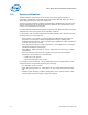
Table 6-1. Processor Thermal Solution Requirements & Boundary Conditions
Case
External
Ambient
IOH
Power
Processor
Power
T
A-Local
Target
Psi-ca
Output
Airflow
1 35 °C TDP TDP 39 °C 0.23 °C/W 756 LFM[3.8 m/S]
2 25 °C TDP TDP 30 °C 0.30 °C/W 420 LFM[2.1 m/S]
3 25 °C Idle Idle 30 °C 1.54 °C/W 163 LFM[0.83 m/S]