
Specifications


Thermal/Mechanical Design Guide 33
Sensor Based Thermal Specification Design Guidance
Note: This data is taken from the validation of the RCBF5 reference processor thermal
solution. The Ψ
CA
vs. RPM data is available in Table 5-1 at the end of this chapter.
5.4 Fan Speed Control (FSC) Design Process
The next step is to incorporate the thermal solution characterization data into the
algorithms for the device controlling the fans.
As a reminder, the requirements are:
• When the DTS value is at or below T
CONTROL
, the fans can be slowed down; just as
with prior processors.
•When DTS is above T
CONTROL
, FSC algorithms will use knowledge of T
AMBIENT
and
Ψ
CA
vs. RPM to achieve the necessary level of cooling.
This chapter discusses two implementations. The first is a FSC system that is not
provided the T
AMBIENT
information and a FSC system that is provided data on the
current T
AMBIENT
. Either method will result in a thermally compliant solution and some
acoustic benefit by operating the processor closer to the thermal profile. But only the
T
AMBIENT
aware FSC system can fully use the specification for optimized acoustic
performance.
In the development of the FSC algorithm it should be noted that the T
AMBIENT
is
expected to change at significantly slower rate than the DTS value. The DTS value will
be driven by the workload on the processor and the thermal solution will be required to
respond to this much more rapidly than the changes in T
AMBIENT
.
An additional consideration in establishing the fan speed curves is to account for the
thermal interface material performance degradation over time.
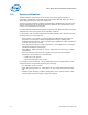
Figure 5-5. Thermal Solution Performance vs. Fan Speed
0.00
0.10
0.20
0.30
0.40
0.50
600 1100 1600 2100 2600 3100 3600
RPM
Psi-ca
1.9
2.4
2.9
3.4
3.9
4.4
4.9
5.4
5.9
Bels (BA)
Psi-ca System (BA)