
Specifications


Thermal/Mechanical Design Guide 29
Sensor Based Thermal Specification Design Guidance
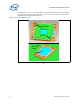
As in previous product specifications, a knowledge of the system boundary conditions is
necessary to perform the heatsink validation. Section 5.3.1 will provide more detail on
defining the boundary conditions. The TTV is placed in the socket and powered to the
recommended value to simulate the TDP condition. See Figure 5-2 for an example of
the processor TTV thermal profile.
Note: This graph is provided as a reference. Please refer to the appropriate processor
datasheet for the specification.
5.2.2 Specification When DTS value is Greater than T
CONTROL
The product specification provides a table of Ψ
CA
values at DTS = T
CONTROL
and
DTS = -1 as a function of T
AMBIENT
(inlet to heatsink). Between these two defined
points, a linear interpolation can be done for any DTS value reported by the processor.
A copy of the specification is provided as a reference in Table 5-1 of Section 5.6.
The fan speed control algorithm has enough information using only the DTS value and
T
AMBIENT
to command the thermal solution to provide just enough cooling to keep the
part on the thermal profile.
As an example, the data in Table 5-1 has been plotted in Figure 5-3 to show the
required Ψ
CA
at 25, 30, 35, and 39 °C T
AMBIENT
. The lower the ambient, the higher the
required Ψ
CA
which means lower fan speeds and reduced acoustics from the processor
thermal solution.
In the prior thermal specifications this region, DTS values greater than T
CONTROL
, was
defined by the processor thermal profile. This required the user to estimate the
processor power and case temperature. Neither of these two data points are accessible
in real time for the fan speed control system. As a result, the designer had to assume
the worst case T
AMBIENT
and drive the fans to accommodate that boundary condition.
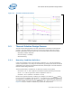
Figure 5-2. Thermal Profile
40.0
45.0
50.0
55.0
60.0
65.0
70.0
0 102030405060708090100110120130
TTV Power (W)
TTV Tcase in C
y = 43.2 + 0.19 * P