M8701A / M8702A ACL Tape Library Installation and User’s Guide Abstract This guide provides information about installing, operating, and maintaining the M8701A and M8702A on HP NonStop™ Integrity NS-series servers and Blade Systems. This guide is written for those who install or maintain the M8701A and M8702A. Product Version N.A. Supported Release Version Updates (RVUs) This publication supports J06.14 and all subsequent J-series RVUs and H06.
Document History Part Number Product Version 694636-001 N.A.
M8701A / M8702A ACL Tape Library Installation and User’s Guide Glossary Index Examples What’s New in This Manual v Manual Information v New and Changed Information Figures Tables v 1. Overview and Features Overview 1-1 Front Panel Overview 1-2 Back Panel Overview 1-4 2. Installing and Configuring the ACL Tape Drive for the NonStop NS-Series Server Overview 2-1 2-2 Installation 2-3 Configuration 2-7 3.
5. Troubleshooting Contents Configuration 4-14 Operations 4-26 Support 4-27 Operator Control Panel (OCP) 4-31 LED Indicators 4-31 ACL Home Screen 4-32 Operator Control Panel Buttons 4-33 Menu Structure 4-33 LTO Cartridge Media 4-47 Cleaning Cartridges 4-48 Data Cartridges 4-48 Write Protecting Cartridges 4-49 Labeling Tape Cartridges 4-50 Handling Cartridges 4-51 Operating and Storage Environment 4-52 Magazines 4-52 5.
Figures Contents Figure 1-1. Figure 1-2. Figure 1-3. Figure 2-1. Figure 2-2. Figure 2-3. Figure 2-4. Figure 2-5. Figure 4-1. Figure 4-2. Figure 4-3. Figure 4-4. Figure 4-5. Figure 4-6. Figure 4-7. Figure 4-8. Figure 4-9. Figure 4-10. Figure 4-11. Figure 4-12. Figure 4-13. Figure 4-14. Figure 4-15. Figure 4-16. Figure 4-17. Figure 4-18. Figure 4-19. Figure 4-20. Figure 4-21. Figure 4-22. Figure 4-23. Figure 4-24. Figure 4-25. Figure 4-26. Figure 4-27. Figure 4-28. Figure 4-29. Figure 4-30. Figure 4-31.
Tables Contents Figure 4-32. Figure 4-33. Figure 4-34. Figure 4-35. Figure 5-1. Figure 5-2. Figure 5-3. Figure 5-4. Figure 5-5. Figure 5-6. Figure 5-7. Figure 5-8.
What’s New in This Manual Manual Information M8701A / M8702A ACL Tape Library Installation and User’s Guide Abstract This guide provides information about installing, operating, and maintaining the M8701A and M8702A on HP NonStop™ Integrity NS-series servers and Blade Systems. This guide is written for those who install or maintain the M8701A and M8702A. Product Version N.A. Supported Release Version Updates (RVUs) This publication supports J06.14 and all subsequent J-series RVUs and H06.
What’s New in This Manual New and Changed Information M8701A / M8702A ACL Tape Library Installation and User’s Guide—694636-001 vi
1 Overview and Features This section includes: Overview 1-1 Front Panel Overview 1-2 Back Panel Overview 1-4 Overview The M8701A and M8702A units support the LTO-5 fibre channel tape drive. They are designed for backup operations for NonStop NS-series servers and Blade Systems. The M8701A comes in a rackmount 2U configuration, and the M8702A comes in a tabletop 2U configuration. These units are shipped and configured as sequential autoloaders.
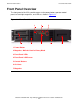
Front Panel Overview Overview and Features Front Panel Overview The front panel of the ACLs provide access to the power button, operator control panel, left and right magazines, and LEDs as shown in Figure 1-1. Figure 1-1. Front Panel Overview 1 2 6 3 4 5 6 7 1. Power Button 2. Magazine / Mailslot Used in Library Mode 3. Front Panel LEDs 4. Front Panel LCD Screen 5. Control Buttons 6. Air Vents 7.
Front Panel Overview Overview and Features The operator control panel includes four LEDs that indicate system status information as shown in Figure 1-2. Figure 1-2. Operator Control Panel LEDs 1 2 3 4 Table 1-3. Operator Control Panel LEDs 1. Green Ready. Illuminated when power is on. Blinking when there is tape drive or robotics activity. 2. Amber Clean. Illuminated when the tape drive has determined that a cleaning cartridge should be used.
Back Panel Overview Overview and Features Back Panel Overview The back panel provides access to the fans, power connector, tape drive, and the fibre channel ports. These ACLs support the LTO-5 fibre channel tape drive. Figure 1-3. Back Panel Overview 1 2 1 3 4 5 6 1. Fan 2. AC Power Connector 3. Tape Drive 4. Fibre Channel Ports 5. Pull-Out tab containing serial number and drive information 6. Ethernet Port 7. Serial Port (Factory Use Only) 8.
2 Installing and Configuring the ACL Tape Drive for the NonStop NSSeries Server This section includes: Overview 2-1 Installation 2-3 Configuration 2-7 Overview A multimode shortwave fiber-optic cable must be used to connect the ACL tape drive to the Fibre Channel ServerNet adapter (FCSA) on the HP NonStop NS-series server. Figure 2-1 shows how the ACL tape drive connects to the server.
Installing and Configuring the ACL Tape Drive for the NonStop NS-Series Server Figure 2-1.
Installing and Configuring the ACL Tape Drive for the NonStop NS-Series Server Installation Installation A LC-LC fiber-optic cable must be used to connect the ACL tape drive to the FCSA on the NonStop NS-series server. Figure 2-2 shows the cable. Table 2-1. Fiber Cables Connector Fiber Cable Fiber Cable Distance LC - LC 50/125 µm 2-300 meters (6.56-984.25 feet) LC - LC 62.5/125 µm 3-150 meters (9.84-492.13 feet) Figure 2-2.
Installing and Configuring the ACL Tape Drive for the NonStop NS-Series Server Installation 1. Connect one end of the fiber cable to the Fibre Channel port at the rear of the tape drive. See Figure 2-3 for the location. Figure 2-3.
Installing and Configuring the ACL Tape Drive for the NonStop NS-Series Server Installation 2. Connect the other end of the fiber cable to the Fibre Channel ServerNet adapter (FCSA) on the NonStop NS-series server. See Figure 2-4 on page 2-5 for the location. Figure 2-4.
Installing and Configuring the ACL Tape Drive for the NonStop NS-Series Server Installation 3. Attach the power cord to the ACL tape drive’s AC power receptacle. See Figure 2-5. Then plug the other end into an AC power outlet. Note. The tape drive does not have protection against lightning surges. Customers in high-risk areas should use external surge protection rated for use in their location and be able to handle the power demand of the tape drive. Figure 2-5.
Installing and Configuring the ACL Tape Drive for the NonStop NS-Series Server Configuration Configuration The tape drive’s worldwide portname will be needed when configuring the device to the NS-series server. The worldwide portname will be listed in the ACL’s menu configuration. 1.
Installing and Configuring the ACL Tape Drive for the NonStop NS-Series Server M8701A / M8702A ACL Tape Library Installation and User’s Guide—694636-001 2 -8 Configuration
3 Configuring the ACL Tape Drive for the NonStop BladeSystem Server This section covers: Configuration Overview 3-1 Adding the Tape Drive 3-1 Start the Tape Drive 3-2 Verify the Tape Configuration 3-2 Troubleshoot the Tape Configuration 3-3 Configuration Overview NonStop BladeSystems can connect to the tape drive by means of a CLIM (CLuster I/O Module). Each CLIM provides access to the tape drive through a Fibre Channel port.
Configuring the ACL Tape Drive for the NonStop BladeSystem Server Start the Tape Drive Start the Tape Drive After the tape drive is added, use the START command to start it: -> START TAPE $M8701A Verify the Tape Configuration To check that the tape drive was successfully added, issue the SCF STATUS tapename, detail command: ->STATUS TAPE $M8701A, DETAIL STORAGE - DETAILED STATUS TAPE \OSMQA5.
Configuring the ACL Tape Drive for the NonStop BladeSystem Server Troubleshoot the Tape Configuration Troubleshoot the Tape Configuration ! ! Check that the processes on the CLIM are running and if they are not, start them. If either of these conditions occur: " The SCF STATUS CLIM $ZZCIP.
Configuring the ACL Tape Drive for the NonStop BladeSystem Server Troubleshoot the Tape Configuration M8701A / M8702A ACL Tape Library Installation and User’s Guide—694636-001 3 -4
4 Operation This section includes: Remote Management Interface (RMI) 4-1 Operator Control Panel (OCP) 4-31 LTO Cartridge Media 4-47 Remote Management Interface (RMI) Overview The remote management interface (RMI) lets you monitor and control your device through the World Wide Web (WWW). The RMI hosts a dedicated, protected Internet site that displays a graphical representation of your device.
Status Pane Operation used with the RMI. If the administrator password is lost, contact customer service to generate a temporary password that will grant administrator access. ! Service — access to this level is by Service personnel only. The service password is set at the factory. The same service password is used for the RMI and OCP. The user login provides access to the Identity and Status options, but not the Configuration, Operations, and Support options.
Getting Help Operation ! ! Slots (Free/Total) — Free is the number of empty storage slots. Total is the number of storage slots available to the host software, which does NOT include reserved slots. Library Time — the date and time from the Library, which can be set from the OCP or RMI. The Library Time is updated when the system status is refreshed. The time of the most recent refresh is the Updated time at the top of the pane.
Identity Operation Identity Viewing Static Device Information Figure 4-4 provides static information about the device. Figure 4-4. Identity: Library Page You can see, but not modify, the following: ! ! ! ! ! Serial Number — the electronic serial number for the device. It should match the serial number printed on the device's label, located on the pull out tab under the drive on the back of the device. Product ID — how the device identifies itself to the host computer.
Identity Operation ! ! ! Random — the device will not automatically load and unload tapes. Instead, it will wait for commands from the backup software or the OCP to load and unload tapes. Sequential — the device will automatically unload the tape in the drive when the host software sends an unload command to the drive and then automatically load the tape from the next highest sequentially numbered full slot.
Identity Operation Figure 4-5. Identity: Drive Page (Fibre Channel) You can see, but not modify, the following: ! ! ! ! ! ! Vendor ID — will always be HP. Product ID — product identification information that is given by the drive. Serial Number — electronic serial number of the drive. It should match the physical serial number of the drive. Firmware Revision — version of the currently installed drive firmware. SCSI ID (parallel SCSI drive only) — SCSI address of the drive.
Identity Operation ! ! ! ! ! ! ! Physical Drive Slot Number — the physical location of the drive. By default, the drives are numbered from the bottom of the device up, starting with number 1. SCSI Element Address (parallel SCSI or SAS drive) or Element Address (FC drive) — element address. The SCSI Element Address is set at the factory and can only be configured by a host application. Library LUN Hosted by Drive — Yes, if this drive is hosting the Library at LUN 1.
Identity Operation Figure 4-6. Identity: Network Page You can see, but not modify: ! ! MAC Address — a unique identifier for the library controller network interface Full Qualified Domain Name — the fully qualified domain name for the device When IPv4 Addressing is Enabled, you can see, but not modify: ! ! ! ! ! IPv4 DNS Server 1 and IPv4 DNS Server 2 — addresses of the configured DNS servers used when DHCP Addressing is not Enabled.
Status Operation the MAC address. The device can manage up to five global addresses at the same time, which can be assigned from different routers. ! ! ! DHCPv6 Addressing — when Enabled, the will request an IP address from a DHCP server each time the device is booted. Static Addressing — when Enabled, the device will use a statically-configured address. Static Assigned Address — the IPv6 address when Static Addressing Enabled is On.
Status Operation ! Status — the overall status of the device The device is fully operational and no user interaction is required. User attention is necessary, but the device can still perform most operations. User intervention is required and the device is not capable of performing some operations. ! ! ! ! ! ! Cartridge in Transport — the slot number where the tape currently in the robot originated. None if there is not a tape in the robotic.
Status Operation Viewing Dynamic Drive Information The Status: Drive page (Fibre Channel) provides detailed information about the drive in the Library. When you click Refresh, the status is updated immediately. Figure 4-8. Status: Drive Page (Fibre Channel) You can see, but not modify, the following: ! Status of the drive The drive is operating normally. The device is functional, but might have an issue that should be addressed. The drive is in a failed state.
Status Operation Note. The Internal Drive Temperature is not the temperature of the tape path in the drive nor is this the operating environment temperature. ! ! ! ! ! ! ! Cooling Fan Active — On if the cooling fan is on Drive Activity — the current drive activity Port A Status and Port B Status (Fibre Channel tape drives) — current status of the ports Speed (Fibre Channel drives) — the current speed setting of the drive port Port Type (Fibre Channel drives only) — the current setting of the drive port.
Status Operation A dark rectangle indicates a full slot, a red rectangle indicates a cartridge with a problem, and a white rectangle indicates an empty slot. To see detailed information about the tapes in a magazine, click on the + button to expand the display for the magazine (see Figure 4-10). Figure 4-10. Status: Inventory: Media Details Pane In the media details pane, ! ! ! ! ! ! ! Slot # — lists “Mailslot” or the index number of each slot in the magazine from lowest to highest.
Configuration Operation Configuration Changing the System Configuration Use the to modify the system configuration. System configuration changes are only applied after the Apply Selections or the Submit button is selected. After making the selection, a warning page informs you of the impact of the proposed change. In some cases a pop-up screen asks you to confirm the change. Many changes also require the device to reboot. You may need to click Refresh to see the changes.
Configuration Operation of the bar code label 12345678, if alignment is left, the device will report 123456. If alignment is right, the device will report 345678. The default is left. ! ! Ignore Barcode Media ID — when disabled, the barcode Media ID on the tape cartridges will be checked by the device. The device will only allow appropriate tape cartridges to be loaded into tape drives. The barcode Media ID is the last two characters of the barcode.
Configuration Operation into the tape drive while in Sequential mode, you can set the Loop and Autoload options. ! ! When Autoload mode is set, the device automatically loads the cartridge from the lowest numbered full slot into the tape drive. It then follows standard sequential operation. When Loop mode is on, the original first cartridge in the sequence is reloaded after the device has cycled through all available cartridges.
Configuration Operation ! ! ! ! Speed — Automatic, 1 Gb/s, 2 Gb/s, or 4 Gb/s. The default is Automatic. Port Type — Automatic, Fabric (N), or Loop (NL). Direct connected devices are typically Loop. Devices connected to a switch are typically Fabric. The default is Automatic. Addressing Mode — addressing mode when the port type is Loop: Hard, Soft, or Hard autoselect. If the Addressing Mode is Hard, you must configure a fixed ALPA address that is unique on the loop.
Configuration Operation Changing the Network Configuration Use the Configuration: Network page to modify the current network configuration. When you request a change, a pop-up box will ask you to confirm the changes. Figure 4-12. Configuration: Network Page You may change the: ! ! ! Protocol version — selects the Internet Protocols that will be enabled. Select IPv4 only, IPv6 only, or both IPv4 and IPv6 protocols. The default is the IPv4 protocol only.
Configuration Operation ! Enable HTTPS — when On, the RMI can only be accessed through an HTTPS connection. For IPv4, you may change the: ! ! ! ! ! DHCP Address — when On, the Library will request an IP address from a DHCP server each time the device is booted. The default is On. Static Address — configures the IP address if DHCP is not enabled. Subnet Mask — configures the network mask of the library controller if DHCP Address is not On.
Configuration Operation Figure 4-13. Configuration: Network Management Page You may change the: ! ! ! SNMP Enabled — When checked, the device can be managed by computers listed in the SNMP Target IP Addresses field. SNMP Target IP Addresses — the IP addresses for up to three computers running IPv4 SNMP management software and up to three computers running IPv6 SNMP management software.
Configuration Operation ! SNMP Trap Notification Filter — the types of events for which the device should send SNMP traps. Changing the Administrator Password Use the Configuration: Password page to change the administrator password for the RMI and OCP. Note. You must set the administrator password with the OCP before you can access administrator functionality in the RMI. Figure 4-14. Configuration: Password Page The password is exactly eight numbers, each between 0 and 9.
Configuration Operation Figure 4-15. Configuration: Date/Time Page Setting Error Log Mode The Configuration: Log page can only be accessed by Service personnel. Figure 4-16.
Configuration Operation Setting Event Notification Parameters The Configuration: Alerts page lets you configure e-mail notification of device events. Figure 4-17. Configuration: Alerts Page You may change the: ! ! ! ! Notification Level — the types of events for which the device should send e-mail To Email Address — the address to which to send the reported events (e.g. firstname.lastname@example.com). Only one email address can be configured. Email Domain — domain of the return e-mail address (e.g.
Configuration Operation the network or ensure that only one device with the same network configuration is on the network at a time until they have unique network identities. Note. You can save the device configuration to a USB flash drive from the OCP. Figure 4-18.
Configuration Operation The following settings are not reset: ! ! ! Administrator password Network settings (network is always enabled and the network addresses are retained) Date and time IMPORTANT: When the defaults are restored, the Library will rediscover and renumber the tape drives from the bottom of the Library up. If a tape drive was added between two other tape drives since the last time the drives were discovered, that tape drive and the ones above it will be renumbered.
Operations Operation Operations Moving Media Use the Operations: Move Media page to move tape cartridges within the device. IMPORTANT: Moving media manually can interfere with backup software operations. Ensure backups are complete before moving media. Figure 4-19. Operations: Move Media Page To move a tape, select the source and destination and then click the Move button in the center of the screen to start the move.
Support Operation Figure 4-20. Operations: Inventory Page Releasing and Replacing the Magazines Use the Operations: Magazine page to release the right or left magazine. When you click Release, the device will unlock the magazine and display Left Magazine Unlocked or Right Magazine Unlocked on the OCP screen. The magazine does not move until you pull it out of the device. If you do not remove the magazine within a few seconds, the device will lock it.
Support Operation Figure 4-22. Support: General Diagnostic Page The available tests are: ! ! Demo — moves cartridges from the slots to the drives and back. At the end of the test the cartridges are returned to their original slots. Slot to slot — shuffles the cartridges between slots to exercise the robot. At the end of the test the cartridges are NOT returned to their original slots. The demo and slot to slot test are intended to show the device operating.
Support Operation Determining and Updating Firmware Use the Support: Firmware page to see the current version of the device and drive firmware, and upload new firmware. The firmware files must have a .frm file extension. After the firmware is updated, the device or tape drive with updated firmware is reset. Caution. Do not interrupt the device while a firmware update is in progress. Updating the tape drive firmware can take several minutes because the firmware is transferred through a serial connection.
Support Operation Viewing Logs From the Support: Library Logs page you can see the device logs. The available logs are: Error Trace, Informational Trace, Warning Trace, Configuration Change Trace, and Standard Trace. The log entries are displayed in order of most recent to oldest. The format for the log entries is: YY.MM.DD HH.MM.SS.ss LIB/ERR<80 89 62 40 ! ! ! ! ! ! YY.MM.DD — the date displayed as Year.Month.Day HH.MM.SS.ss — the time displayed as Hour.Minute.Second.
Operator Control Panel (OCP) Operation Figure 4-27. Support: Clean Drive Page Downloading a Support Ticket Use the Figure 4-28 to download a support ticket for the Library or tape drives. The support ticket can help a service engineer or system administrator diagnose a device problem. You can view the contents of the support ticket with HP Library & Tape Tools. Figure 4-28.
ACL Home Screen Operation Figure 4-29. Operator Control Panel LEDs 1 2 3 4 Table 4-1. Operator Control Panel LEDs 1. Green Ready. Illuminated when power is on. Blinking when there is tape drive or robotics activity. 2. Amber Clean. Illuminated when the tape drive has determined that a cleaning cartridge should be used. Cleaning is only necessary when the device directs you to do so. Additional cleaning is not necessary. 3. Amber Attention.
Operator Control Panel Buttons Operation Table 4-2. Drive status Status Definition RWD Drive is rewinding SEEK Drive is seeking ERS Drive is erasing a tape FORM Drive is formatting a tape CAL Drive is calibrating RMVD Drive has been removed OFF Drive is disabled No Drive The drive is physically and logically not present. Operator Control Panel Buttons The four operator control panel buttons, described in Figure 4-30, let you traverse the OCP menu structure and enter information.
Menu Structure Operation From the Home screen, press Enter to bring up the first menu item. From a menu, use the Previous and Next keys to cycle through the menus, press Enter to see the first option in the menu, or press Cancel to return to the Home screen. From an option, use the Previous and Next keys to cycle through the options in the menu, press Enter to select the option, or press Cancel to return to the menu list. The menu structure is shown in Figure 4-31.
Menu Structure Operation Figure 4-31.
Menu Structure Operation Entering the Administrator Password The administrator password accesses all of the available functionality, except for the Service Area. A user without the administrator password has access to the Status/Information menus. Tip. By default, the administrator password is unset; all of the digits are null. You must set the administrator password from the OCP to protect the administrator functions on the OCP and enable the administrator functions in the RMI.
Menu Structure Operation Each location provides different information: ! ! Drive: The screen display may read AESO32L3, where AESO32L3 is an example of the bar code number on the tape, or it may read Full or Empty. Left or right magazine: The screen display may read Left Magazine or Right Magazine. The second line on the display indicates which slots have a tape or are empty. Slots in the left magazine are numbered 1-12 or 1-11, and slots in the right magazine are numbered.
Menu Structure Operation Library Information (Status/Information > Library Information) To obtain information about your device: 1. From the Home screen press Previous or Next until the screen displays Status/Information. Press Enter to select. 2. Press Previous or Next until the screen displays Library Information. Press Enter to select. By using Previous or Next, you can select from the following information screens: ! ! ! ! ! ! ! ! ! ! Library Time Firmware rev.
Menu Structure Operation ! The WWide Port Name and Port Type for Port B. World Wide names are assigned automatically; they cannot be configured. Component Status (Status/Information > Component Status) To obtain component status: 1. From the Home screen, press Previous or Next until the screen displays Status/Information. Press Enter to select. 2. Press Previous or Next until the screen displays Component Status. Press Enter to select. 3.
Menu Structure Operation 4. For IPv4 Network or IPv6 Network, press Enter and then use Previous or Next to access the network addresses and configuration. Configuration To access the Configuration menu: 1. From the Home screen, press Previous or Next until the screen displays Configuration. Press Enter to select. 2. Press Previous or Next until the screen displays your selected function. Press Enter to select.
Menu Structure Operation manage the cleaning process. You can reserve up to 22 slots. Access to this feature requires the administrator password. To set the reserved slot count: 1. From the Home screen, press Previous or Next until the screen displays Configuration. Press Enter to select. 2. Press Previous or Next until the screen displays Set Reserved Slot Count. Press Enter to select. 3. Enter the administrator password if prompted. 4.
Menu Structure Operation The device can use a cleaning cartridge from any slot, even if the slot is reserved. The device keeps track of the usage count for each of the cleaning cartridges. When multiple cleaning cartridges are available, the device will first choose an unknown cleaning cartridge so the device can start tracking the cartridge usage count. If the device knows the usage count for all of the cleaning cartridges, the device will choose the one with the highest usage count.
Menu Structure Operation 4. Press Enter to select the desired magazine to unlock. 5. Enter the administrator password if requested. 6. The display reads Left Magazine Unlocked or Right Magazine Unlocked. 7. Pull the released magazine out of the device. 8. The screen now displays Insert Left Magazine or Insert Right Magazine. The device cannot perform any other operation until the magazine is replaced. After exchanging tapes in a magazine, slide the magazine completely into the device.
Menu Structure Operation detect that a cleaning tape with a bar code is in the device. In this case, the operator must select the slot where a cleaning tape resides. 6. Use Previous or Next to display the location of a cleaning tape. 7. When the correct location for the cleaning tape is displayed, press Enter to select. While the device cleans the drive, Cleaning Drive in progress or Cleaning Drive 2 in progress it displays. 8.
Menu Structure Operation ! ! ! Right Magazine Left Magazine Drive 1 8. When the correct destination is displayed, press Enter to select. 9. If the destination selected is a magazine, use Previous or Next to display the slot. Only empty slots are listed. Once the correct slot is displayed, press Enter to select. The device now moves the tape from the selected source, to the selected destination. While the device moves the tape, the screen displays Moving Tape.
Menu Structure Operation 3. The Ready LED blinks during the reboot operation. Enabling Password Locks (Operations > Enable Library Password Locks) This option locks the restricted areas. This is typically used if you do not want to wait for the time out to reset the locks. Power cycling or rebooting the device also resets the locks. To enable the password locks: 1. From the Home screen, press Previous or Next until the screen displays Operations. Press Enter to select. 2.
LTO Cartridge Media Operation demonstration the device will move cartridges to the tape drive and back. At the end of the demonstration the cartridges are returned to their original slots. Access to this feature requires the administrator password. To run the demonstration: 1. From the Home screen, press Previous or Next until the screen displays Support. Press Enter to select. 2. Press Previous or Next until the screen displays Run Demo. Press Enter to select. 3.
Cleaning Cartridges Operation they can cause loader faults and interfere with normal operations. Such labels can come off inside the equipment causing damage. 2. Always inspect cartridges for incorrect or improperly attached labels. 3. Never erase information on a cartridge label, always replace the label. Note. Barcode labels may be placed on the media with the alphanumeric characters on the left or the right. Figure 4-32.
Write Protecting Cartridges Operation Compatible media can be recognized by the Ultrium logo, which is the same as the logo on the front of your drive. Do not use other format cartridges in your tape drive and do not use LTO cartridges in other format tape drives. For optimum performance always use a data cartridge that matches the specification of your tape drive, (see table below).
Labeling Tape Cartridges Operation Figure 4-33. Write Protecting a Tape Cartridge 1 1. Write Protect Tab CAUTION: Write protection will not protect your cartridges against magnets. Write-protection will not prevent a cartridge being erased by bulk-erasure or degaussing. Do not bulk erase Ultrium format cartridges. This will destroy pre-recorded servo information and make the cartridge unusable.
Handling Cartridges Operation Tip. The bar code scanner must scan each tape or the back of the storage slot until it reads the bar code label for the cartridge or storage slot, or determines that the slot is empty. The bar code scanner can identify a properly labeled cartridge on the first scan. It can identify an empty slot on the second scan.
Operating and Storage Environment Operation 5. Do not leave cartridges in direct sunlight or in places where magnetic fields are present (for example, under telephones, next to monitors or near transformers). 6. Do not drop cartridges or handle them roughly. 7. Stick labels onto the label area only. 8. Do not bulk erase (or degauss) Ultrium format cartridges because this will render them unusable.
Magazines Operation Figure 4-35.
Magazines Operation M8701A / M8702A ACL Tape Library Installation and User’s Guide—694636-001 4- 54
5 Troubleshooting This section includes: Fibre Channel Connection Problems 5-1 Operation Problems 5-2 Service and Repair 5-8 The Wellness Test 5-10 Error Codes 5-11 Warning Events 5-26 Caution. This ACL is designed to operate when installed in a rack using the rack rail kit. Operating the ACL without installing it in the rails, such as on a table or rack shelf, could result in device errors. Placing any weight on top of the device might also cause errors. Caution.
Operation Problems Troubleshooting ! ! The cable is damaged. FC cables are delicate. If the cable has been bent or twisted sharply, it may be broken and must be replaced. If the screen shows ALPA Conflict: There might be a conflict with the ALPA address on Loop ports. Select Soft for the Loop mode to allow the system to select an available address each time the tape drive connects to the FC fabric.
Operation Problems Troubleshooting Table 5-1. Problems Problem Solution Tape stuck in drive. Try the following steps, in this order, to remove the stuck tape. NOTE: The tape drive must rewind the tape before ejecting it. This can take as long as five minutes, depending on how much tape must be rewound. Once the tape is rewound, the eject cycle will take fewer than 16 seconds. The READY light flashes while the tape rewinds. Wait for the tape to finish rewinding before attempting another operation. 1.
Operation Problems Troubleshooting Table 5-1. Problems Problem Solution Tape stuck in storage slot. To remove a stuck tape from a storage slot: If the operator control panel or the remote management interface is still operational: 1. Move the tapes from the drives to the magazines using the Move Tape command. 2. Use the magazine removal process to release the magazine and remove it from the device.
Operation Problems Troubleshooting Table 5-1. Problems Problem Cannot write to or read from tape. Solution ! ! ! ! ! ! ! ! ! Make sure that the cartridge is not a WORM cartridge that has already been used. Make sure that the cartridge is write enabled (move the write-protect switch to the enabled position). Make sure the data cartridge is compatible with the drive model. LTO tape drives can read data cartridges from two generations back and write to data cartridges one generation back.
Operation Problems Troubleshooting Table 5-1. Problems Problem Solution Both the Attention and Cleaning LEDs are lit. This is most likely caused by a dirty drive that cannot read a tape and marks the tape invalid. 1. View the inventory with the RMI. Note the slots that have tapes marked with !. 2. Remove any magazines that contain tapes marked with !. 3. Remove the tapes that were marked with !. 4.
Operation Problems Troubleshooting Table 5-1. Problems Problem Solution The Cleaning LED is lit after using a cleaning cartridge. The cleaning cartridge is expired. A cleaning cartridge will expire after 50 cleaning cycles. A particular cartridge sets off the Attention LED and possibly the Cleaning LED.
Service and Repair Troubleshooting Service and Repair Releasing the Magazines Manually If you cannot remove the magazines via the OCP, do the following: 1. Unplug the power cord from the device. 2. From the back of the device, find the access holes for the right and left magazines. See Figure 5-1. Figure 5-1.
Releasing the Magazines Manually Troubleshooting 3. To manually release a magazine, push the end of a small metal pin or straightened paper clip into the magazine access hole at the back of the device. While holding the paper clip, have a second person attempt to pull the magazine out of the front of the unit. See Figure 5-2. Figure 5-2. Releasing the Magazine Pull the magazine out of the front of the unit. Push a paper clip into the access hole. IMPORTANT.
Troubleshooting The Wellness Test The Wellness Test The wellness test exercises all ACL and tape drive hardware, except the external connections, and is useful for verifying that a device is working correctly. For complete testing ensure that each corner slot contains a tape cartridge. Figure 5-3 shows the 2U top-row corner slots: 9, 12, 21, 24 Figure 5-3. Top-Row Corner Slot Positions IMPORTANT: The ACL will remove any tape cartridges from the tape drives and go offline when running the wellness test.
Troubleshooting Error Codes 3. The device returns any tape cartridge from the tape drive to their home slots. If the home slot for a cartridge is not known, the device will move the cartridge and prompt the operator to remove it. 4. The device prompts the operator to enter the number of cycles to run the test. 5. The device prompts the operator to insert a scratch cartridge. 6.
Troubleshooting Finding Error Code Information on the OCP Finding Error Code Information on the OCP When an error first occurs, the error message and error code are displayed on the OCP, as shown in Figure 5-4. Figure 5-4. Initial OCP Error Message The code 9B is the main error code, and 37 is the error sub-code. If you review the Error Log in the Support menu, the OCP error log displays the error code, as shown in Figure 5-5. Figure 5-5.
Main Error Code Descriptions Troubleshooting If you press Next, the OCP will display additional information, if available, as shown in Figure 5-7. Figure 5-7. No Additional Information in the OCP Error Log If you press Next again, the OCP will display the date and time in the format: YYYYMM-DD followed by the time in 24–hour clock format, where 1:00 pm is 13:00, as shown in Figure 5-8. Figure 5-8. Date and Time in the OCP Error Log Main Error Code Descriptions Table 5-2.
Main Error Code Descriptions Troubleshooting Table 5-2. Main Error Codes Error Code Description Details and Solution 86 Setting of elevator motor parameters failed Power-cycle the unit and retry the operation. 87 Setting of rotation motor parameters failed Power-cycle the unit and retry the operation. 88 Setting of sled motor parameters failed Power-cycle the unit and retry the operation.
Main Error Code Descriptions Troubleshooting Table 5-2. Main Error Codes Error Code Description 8D Sled obstructed Details and Solution ! ! ! ! ! 8E Ends of gripper movement not in expected range If this error occurs on the first power-on after unpacking or moving the device, or after replacing the chassis, ensure that the shipping lock was removed from the top and stored on the back panel.
Main Error Code Descriptions Troubleshooting Table 5-2. Main Error Codes Error Code Description 8F Ends of slider movement not in expected range Details and Solution ! ! ! ! ! 90 Ends of elevator movement not in expected range 91 Ends of rotation movement not in expected range If the error consistently happens on the same slot, try different tape cartridges in that slot. If the failure remains with the same slot, the magazine may be at fault.
Main Error Code Descriptions Troubleshooting Table 5-2. Main Error Codes Error Code Description Details and Solution 9D Slider2 range of motion out of specification Run the wellness test. 9E Elevator3 range of motion out of specification Run the wellness test. 9F Rotation range of motion out of specification Run the wellness test. A0 Sled range of motion out of specification Run the wellness test.
Main Error Code Descriptions Troubleshooting Table 5-2. Main Error Codes Error Code Description B5 Robotic controller not responding to command from library controller Details and Solution ! ! ! C0 Network initialization failed ! ! ! ! C1 Telnet interface initialization failed ! ! ! C2 Web server initialization failed ! ! ! C6 Ping command did not reach target ! ! ! C7 Cannot upgrade firmware from USB ! Reset the device and retry the operation.
Main Error Code Descriptions Troubleshooting Table 5-2. Main Error Codes Error Code Description C8 Cannot upgrade firmware from FTP Details and Solution ! ! ! C9 Cannot upgrade robotic firmware from USB. ! ! ! D0 ROM checksum incorrect ! ! Ensure that the correct file was selected. Retry firmware upgrade. If not successful, attempt a different firmware upgrade method. Retry firmware upgrade. If not successful, attempt a different firmware upgrade method.
Main Error Code Descriptions Troubleshooting Table 5-2. Main Error Codes Error Code Description DC I2C Bus failure DD Warning event. See DD in “Warning events” DE Warning event. See DE in “Warning events” E2 Unsupported hardware detected. Some hardware that is connected to the requires updated firmware.
Main Error Code Descriptions Troubleshooting Table 5-2. Main Error Codes Error Code Description F5 Time allotted for drive unloading exceeded Details and Solution ! ! ! F6 No drive installed. A tape drive has never been installed. F7 Support ticket download from drive not possible. F8 Invalid drive command ! ! Invalid drive parameter ! ! ! ! FA SDCI microcode error Attempt the Force Tape Eject process.
Main Error Code Descriptions Troubleshooting Table 5-2. Main Error Codes Error Code Description FB Drive logged out Details and Solution ! ! ! FC FD Internal SCSI command failed with check condition Internal SCSI command time-out ! ! ! Update the tape drive firmware to the current version. Try the operation again. If the error occurs again contact customer support. Update the tape drive firmware to the current version. Try the operation again. If the error occurs again contact customer support.
Error Sub-Code Descriptions Troubleshooting Error Sub-Code Descriptions Robotic Error Sub-Codes Table 5-3.
Error Sub-Code Descriptions Troubleshooting Table 5-3.
Error Sub-Code Descriptions Troubleshooting Table 5-3.
Warning Events Troubleshooting Drive Error Codes Table 5-5. Drive Error Codes Error Code Description 01 Drive broken 02 Temperature exceeds limit 03 Tape error 04 Cleaning cartridge is expired 05 Drive needs cleaning 06 Library lost communication with the drive 07 Warning that the tape is nearing its end of life Warning Events Table 5-6.
Warning Events Troubleshooting Table 5-6. Warning Event Codes Event Code Description 63 Invalid cartridge. Drive has rejected the cartridge as invalid. Details and Solution ! ! ! 64 Invalid cleaning cartridge. Drive has rejected the cartridge as invalid. ! ! ! ! 65 Invalid upgrade cartridge. Drive has rejected the cartridge as invalid. ! ! ! 80 Movement retry. Robotics movement did not succeed but was successful on a retry. 81 Drive sled fan alert. Fan motion has stopped.
Warning Events Troubleshooting Table 5-6. Warning Event Codes Event Code Description 83 Media attention Details and Solution ! ! ! 84 85 Tape drive tape alert; tape drive reported a warning or critical tape alert. DHCP request has failed ! ! ! ! ! ! ! ! Verify that the cartridge and tape drive generation are compatible. Inspect the cartridge for damage. Ensure that the cartridge has not exceeded its usage life. Retry the operation.
Warning Events Troubleshooting Table 5-6. Warning Event Codes Event Code Description 8A Power supply has failed. Redundancy is not available. 8B One of the redundant power supplies has failed. Details and Solution ! ! ! ! ! ! 8C DB Invalid robotics code; does not match with the loaded firmware. External cooling fan error (fan motion has stopped). The subcode indicates which drive sled fan is affected. Subcode 00: drive sled #1 DD Power supply fan has failed, redundancy may be at risk.
Troubleshooting Warning Events M8701A / M8702A ACL Tape Library Installation and User’s Guide—694636-001 5- 30
6 Technical Specifications This section includes: Physical Specifications 6-1 Environmental Specifications 6-1 ACL Specifications 6-2 LTO-5 Media Compatibility 6-2 HP LTO Media Part Numbers 6-3 Physical Specifications Table 6-1. 2U Physical Specifications Characteristics Product Alone Packaged Height 8.7 cm (3.44 inches) 25 cm (9.84 inches) Width 44.5 cm (17.5 inches) 58 cm (22.83 inches) Depth 77.5 cm (30.53 inches) 99 cm (38.97 inches) Weight 15 kg (33.07 pounds) 25.5 kg (56.
ACL Specifications Technical Specifications ACL Specifications Table 6-3. LTO-5 Half-Height ACL Specifications Characteristic Specification Tape Drive LTO-5, Half-Height, Fibre Channel Form Factor 2U Maximum Cartridge Slots 24 Maximum Tape Drives 1 Maximum Storage Capacity: LTO-5 Media Native: 36 TB Compressed (2:1): 72 TB Native Data Transfer Rate 140 MB/s Buffer Size 256 MB Rewind Tape Speed 9 m/s MTBF 250,000 Hours @100% Duty Cycle LTO-5 Media Compatibility Table 6-4.
Technical Specifications HP LTO Media Part Numbers HP LTO Media Part Numbers Table 6-5.
Technical Specifications HP LTO Media Part Numbers M8701A / M8702A ACL Tape Library Installation and User’s Guide—694636-001 6 -4
Index A operator control panel buttons 4-33 powering a drive on or off 4-46 rebooting the library 4-45 setting the date and time 4-41 AC power receptacle 2-6 B Back panel 1-4 overview 1-4 F Fiber optic cable 2-3 Fibre Channel port 2-4 Fibre Channel ServerNet adapter 2-5 Front panel 1-2 operator control panel LEDs 1-3 L LTO cartridge media compatibility 4-49, 6-2 N T Technical specifications 6-1 environmental specifications 6-1 library specifications 6-2 LTO media compatibility 6-2 physical specificat
T Index M8701A / M8702A ACL Tape Library Installation and User’s Guide—694636-001 Index -2