HP Virtual Connect Enterprise Manager 7.1 User Guide Abstract This document is intended to be used by technical professionals who manage multiple HP BladeSystem enclosures and use HP Virtual Connect Manager to control network connectivity. HP assumes that you have installed Virtual Connect, are familiar with the embedded VCM web console, and have read the HP Virtual Connect for c-Class BladeSystem User Guide and understand its concepts.
© Copyright 2007, 2012 Hewlett-Packard Development Company, L.P. Confidential computer software. Valid license from HP required for possession, use or copying. Consistent with FAR 12.211 and 12.212, Commercial Computer Software, Computer Software Documentation, and Technical Data for Commercial Items are licensed to the U.S. Government under vendor's standard commercial license. The information contained herein is subject to change without notice.
Contents 1 Introduction...............................................................................................8 Key features and benefits...........................................................................................................8 Key features........................................................................................................................8 Key benefits................................................................................................................
Adding or removing remote enclosures from a multienclosure domain in VC Domain Maintenance.....................................................................................................................49 Canceling a VC Domain Maintenance task................................................................................49 Resynchronizing a VC Domain with Configuration Mismatch........................................................49 Using FlexFabric modules...........................................
Assigning a server profile to a bay...........................................................................................96 Unassigning a server profile from a bay....................................................................................96 Designating spare bays...........................................................................................................96 Performing a Server Profile Failover.........................................................................................
Profile operations fail, and the error message "An invalid boot LUN was entered. Check the storage arrays for the proper LUN number" appears.............................................................................119 Error popup appears when you select HP predefined ranges during remove VC Domain from group or delete VC Domain Group operations...................................................................................
Create VC Domain Group or Add VC Domain to VC Domain Group operations fail and the message "An invalid boot LUN was entered. Check the storage arrays for the proper LUN number" appears..............................................................................................................................136 Profile move, assign, or failover operations fail and the message "An invalid boot LUN was entered. Check the Storage arrays for the proper LUN number" appears.......................................
1 Introduction VCEM centralizes network connection management and workload mobility for HP BladeSystem servers that use Virtual Connect to access LANs, SANs, and converged network environments. VCEM helps organizations increase productivity, respond faster to workload and infrastructure changes, and reduce operating costs.
• Group-based management of Virtual Connect Domains increases infrastructure consistency, simplifies system deployment and enables rapid change management across hundreds of HP BladeSystem enclosures. • Add, change, and failover servers and their workloads across the data center in minutes without impacting production networks. • Increase productivity and server-to-administrator ratios. • Release LAN and SAN administrators from routine server-centric tasks.
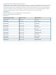
Table 1 (page 10) lists all available VCEM licenses, including Virtual Connect hardware and VCEM packaged options.
• Enables system administrators to be self-sufficient—Add, replace, or modify servers in minutes to meet changing workload and business requirements without impacting production networks. • Relieves LAN and SAN administrators from server-centric maintenance. Figure 1 (page 11) shows a comparison between tradition networks and VC networks.
An important benefit of VC is that server connection profiles and associated attributes are assigned to BladeSystem enclosure bays and not hard wired to individual servers. The physical server in each bay uses the MAC and WWN assignments in the associated server connection profile instead of its default burned-in NIC or HBA addresses. Using this model, even if a server is replaced, the MAC and WWN assignments for the enclosure bay remain constant, and the change is invisible to the network.
• Define server profiles and link to available LAN and SAN network resources. • Assign server profiles to BladeSystem enclosures, enclosure bays, and VC Domain Groups. • Change, move, or automatically failover server profiles to spare servers. • Rapidly install new bare-metal HP BladeSystem enclosures by assigning it to a VC Domain Group.
NOTE: The LANs associated with each uplink port and the attributes of the VC server profile remain exactly the same; only the location of the server profile has changed. When a VC server connection profile is moved, the associated MAC, WWN, boot from SAN parameters, and related workload always move with the server profile. From the VCEM GUI, server profiles can be moved to a user-defined spare server.
2 Installing and configuring VCEM This chapter describes how to install and configure VCEM. IMPORTANT: This guide assumes that you have previously installed VC using the integrated VCM, have read the HP Virtual Connect for c-Class BladeSystem User Guide, and understand its concepts. Preparing for a VCEM installation VCEM upgrade to 7.1 is only available if you have VCEM 6.0 or later installed. VCEM 7.1 can be installed as a new application and allows upgrade paths. IMPORTANT: system.
Mixed VC firmware versions and compatibility in a VC Domain Group VCEM enables firmware compatibility using current and future versions of VC firmware. This feature provides both backward and forward VC firmware compatibility. Backward compatibility for VC firmware You can install VCEM 7.1 and run the latest VC firmware in a VC Domain Group that has an earlier but supported firmware mode. IMPORTANT: The minimum supported firmware version in VCEM 7.1 is VC firmware 3.15.
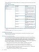
Table 4 VCEM ports (continued) Port Protocol1 Description 22 SSH This port is needed to establish a connection through SSH using CLI Y 161 SNMP (UDP) SNMP Agent/Poll Y 162 SNMP Trap (UDP) Trap listener Y 69 UDP TFTP—Used for upload and configuration backup from CLI Y 20, 21 TCP FTP—Used for upload and configuration backup from CLI Y 636 TCP LDAP Authentication Y 514 UDP SYSLOG Y 1812, 1813 UDP RADIUS server if configured Y 49 TCP TACACS server if configured CMS Y Y Ma
Updating VC firmware VCEM allows you to update VC firmware simultaneously across multiple VCEM managed VC Domains using Firmware Update mode. CAUTION: VC Domains with a status of Fail to communicate with VC domain / Disabled enclosure or Missing external manager lock / Communication established with disabled enclosure can be selected because they have a transient status. The VC Domain can restore communication with VCEM or restore the lock before Enable Firmware Update is allowed.
Figure 7 Enabling firmware updates A message similar to the following is displayed: Figure 8 Firmware update message After the job completes, use the VCSU to perform the firmware update and then proceed to Step 4. 4. Check mark the targeted VC Domains on the VC Domain tab and select VC Domain Firmware Update... again. NOTE: If another VC Domain with a status other than Firmware update is selected, the VC Domain Firmware update button is disabled. 5.
Removing VCEM WARNING! Removing VCEM could have significant implications. Before removing VCEM, verify that no other upper-level management products, such as HP Matrix Operating Environment, are using VCEM capabilities. Uninstallation of VCEM requires a release of all VC Domains. Removing VCEM also removes all VCEM-centric historical tracking of individual WWNs and MAC addresses.
1. 2. Discover the Onboard Administrator IP addresses with enclosures that have VC Ethernet modules. Click VC Domains to verify whether any VC Domains have been discovered. For more information about performing an Systems Insight Manager discovery, see the HP Systems Insight Manager 7.1 User Guide. 4. 5.
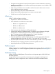
7. (Optional) Use the following procedure to configure the WWN ranges to meet your requirements. NOTE: It is optional to set up a user-defined range in VCEM. This is only required if you are managing VC Domains which use special user-defined WWNs. a. b. c. Click Home from the VCEM home page. To return to the home page in a stand-alone VCEM installation, click the Home link on the upper right-hand corner of the window. Click the World Wide Names hyperlink. To create a custom range, click Add custom.
Upgrading incompatible firmware modes and versions If unsupported VC Domain firmware versions are detected at the end of a VCEM 7.1 upgrade, a warning message similar to the following is displayed: VCEM detected unsupported VC firmware. For information on how to upgrade your firmware, run the Insight Software Advisor or refer to the VCEM User Guide troubleshooting section. Upgrade to a supported VC firmware by performing the following steps: 1.
3 Managing VC Domains This chapter describes how to use VCEM to manage VC Domains. On the VC Domains page, you can filter the VC Domain list by VC Domain Group. The default filter shows all VC Domains. Figure 10 VC Domains window Table 5 (page 24) lists the columns on the VC Domains page.
Table 6 VCEM status icons (continued) Status Icon Description Missing external manager lock/Communication established with disabled enclosure VCEM is unable to obtain the necessary permissions for External Manager user. VCEM might have lost the External Manager lock at the VC Domain. Expired license The VC Domain enclosure has an expired license. Managed by VCEM The VC Domain is part of a VC Domain Group and operating normally.
minimum number of enclosures. For more information about multienclosure VC Domains, see “Working with multienclosure VC Domains” (page 40). • VC Domain names must not already exist in VCEM. • Server profile names must not already exist in VCEM. • MAC or WWN addresses or serial numbers that are assigned to a server profile must not be in use by VCEM or in a VCEM exclusion list.
VCEM validates the following components when adding a VC Domain to a VC Domain group, therefore the VC Domain configuration must be identical to the VC Domain Group configuration.
• 28 For each single network uplink: ◦ Network name ◦ Smart link ◦ Private Network ◦ Enable VLAN Tunneling ◦ State ◦ Network port location ◦ Speed/duplex mode ◦ Connection mode ◦ Preferred Link Connection ◦ Preferred Link Connection Speed ◦ Maximum Link Connection ◦ Maximum Link Connection Speed ◦ Network Access Groups (associated with this network) • Number of networks configured in the VC Domain • For each shared network uplink: ◦ Uplink set name ◦ Network port location
• • ◦ Maximum Link Connection Speed ◦ Network Access Groups (associated with this network) For each Fibre Channel SAN Fabric: ◦ Fabric name ◦ Fabric port location ◦ Configuration speed Number of Fibre Channel SAN Fabrics configured in the VC Domain To add an unconfigured VC Module to a VC Domain Group, the following items must be identical: • Interconnect bays location and model • Enclosure model • Uplinks of the network and Fibre Channel SAN Fabric • Power state of the VC Modules VC 3
VC 3.3x features that must be disabled in a VC Domain to be part of a VC Domain Group with VC firmware 3.15 – 3.18 For a VC Domain to be part of a VC Domain Group with VC firmware 3.15 – 3.18, Hybrid VLAN Tagging, Network Access Groups, Port Throughput Statistics, Custom Module Host Names, Extended Mapped VLANs, and iSCSI Boot Assistant are not supported, as follows: • Hybrid VLAN Tagging in a VC Domain is not supported. VLAN tunneling must be uniformly enabled or disabled for all networks in the domain.
To disable this feature edit all Ethernet Networks to clear the Enable VLAN Tunneling property check box, or edit all Server Profiles to ensure that no Ethernet Adapter Connections are using Multiple Networks. • Network Access Groups are not supported. Do not create Network Access Groups on the VC Domain other than the Default Network Access Group (which is automatically defined by VC). Figure 14 VC Domain with the Default Network Access Group plus another Network Access Group configured.
• Extended Mapped VLAN is not supported. Do not configure the VC Domain to allow for expanded VLAN capacity (Extended Mapped VLAN). Figure 16 VC Domain with Extended Mapped VLAN configured IMPORTANT: The only way to disable this feature is by deleting the entire VC Domain configuration (including server profile configuration). To delete the VC Domain configuration go to the Domain Settings menu in the VCM user interface, click Configuration and then click Delete.
Figure 18 VC Domain with Storage Management Credentials To disable this feature go to the VC Manger user interface and delete all Storage Management Credentials by clicking on Delete in the Edit drop-down menu for each Storage Management Credential. Figure 19 Deleting a Storage Management Credential VC Domain tasks From the VC Domains page, you can perform the following tasks: • License an enclosure. • Create a VC Domain Group. • Add a VC Domain to a VC Domain Group.
4. 5. Click Apply License. Click OK to validate the key string. NOTE: License key fields are case-sensitive If the key string is valid, the key is added to HP Insight Management. 6. • Click Next to provide VC Domain credentials. For existing VC Domain Groups: 1. Select the VC Domain from the VC Domains page, and then click License. The License Enclosure page appears. 2. 3. Click Add Key. Enter the license key string, and then click OK.
If you are using an HP VC FlexFabric 10 Gb 24-port module, ensure that the module status is compatible. See “Upgrading incompatible firmware modes and versions” (page 23) for more information. VCEM cannot manage a VC Domain that has one or more FC modules with an Incompatible status. The FC module can become incompatible in the following situations: • An HP Virtual Connect 4 Gb FC module replaces an HP Virtual Connect 8 Gb 24-port FC module.
6. Select the MAC address range type from the following options: • VCEM-defined • User-defined • Factory-default NOTE: You cannot change any of the range types after creating the VC Domain Group. You can only select the User-Defined option for the MAC range type if a MAC custom range is defined. 7.
• Ensure that the version of VC firmware and the features enabled in the VC Domain are compatible with the group firmware mode of the VC Domain Group to which it is being added. For more information, see “Mixed VC firmware versions and compatibility in a VC Domain Group ” (page 16).
3. 4. 5. 6. 7. 8. 9. (Optional) You can provide a new name for the unconfigured VC Domains. Valid VC Domain Group names are alphanumeric, hyphens (-), underscore (_), and cannot exceed 64 characters. Enter the user name and password for each unconfigured VC Domain. Ensure you provide VC Domain credentials with full privileges.
NOTE: Removing the VC Domain out of the VC Domain Group does not cause any changes to the MACs or WWNs currently in use in the VC Domain. Any new MACs or WWNs assigned through VCM after the VC Domain has been removed from the VC Domain Group will be assigned from the ranges designated when the VC Domain was removed from the VC Domain Group. See “Managing MAC and WWN addresses” (page 98) for more information. To remove one or more VC Domains from a VC Domain Group: 1.
Working with multienclosure VC Domains VCEM supports multienclosure VC Domains. A multienclosure VC Domain is a VC Domain with one local enclosure and up to three remote enclosures. VCEM supports VC Domains with up to four BladeSystem c7000 enclosures. Within each enclosure of a multienclosure domain, the VC Ethernet Modules must follow the same configuration rules as VC Domains with single enclosures. However, each enclosure within the VC Domain might have a different configuration of Ethernet modules.
Figure 21 VC Domain Group with VC Domains that have different numbers of enclosures A multienclosure domain can only be configured as follows: • The enclosure must be a c7000 enclosure. • Refer to the VC documentation available at: http://www.hp.com/go/vc for details on which Virtual Connect Ethernet modules are supported for primary and secondary roles for the VC firmware revision in your environment. • FC modules in every enclosure must match the model and disposition.
VC Domain Maintenance VC Domain Maintenance is a useful way to perform updates on a particular VC Domain without removing it from a VC Domain Group, and apply the common domain, network and storage configuration changes automatically to all other VC Domains that belong to the same VC Domain Group. VCEM accomplishes this task by temporarily enabling domain, network, and storage changes through the local VCM for the selected domain. Figure 22 (page 42) displays VC Domain Maintenance functions.
• Ethernet Settings: ◦ MAC Cache failover ◦ IGMP Snooping ◦ Multiple Networks Link Speed Settings ◦ Server VLAN Tagging Support • Shared Uplink Set • Resetting VC module (soft reset) • Monitoring network ports • Configuring networks • Configuring storage • Login Banner Configuration • Enclosures Configuration: ◦ Find ◦ Import ◦ Delete • Storage Management Credentials • SNMP Configuration • Network Access Groups • Link Stability Redistribution • Support Log Configuratio
The following information is replicated to all VC Domains in the VC Domain Group during VC Domain Maintenance: NOTE: The following information is sample base VC Domain configuration data that is replicated to all VC Domains in the VC Domain Group.
◦ Network Loop Protection ◦ VLAN Capacity – • • Fibre Channel SAN fabric settings: ◦ Enable SMI-S ◦ Fibre Channel SNMP settings: • – Enable SNMP – Read Community – System Contact – Each SNMP trap Community and IP address For each Fibre Channel fabric: ◦ • Legacy VLAN capacity or Expanded VLAN capacity Fabric name For each network uplink: ◦ Name ◦ State ◦ Connection mode ◦ Smart link ◦ Private network ◦ Enable VLAN tunneling ◦ States ◦ Network port location ◦ Speed/d
• ◦ Smart Link ◦ External VLAN ID ◦ Native VLAN ◦ Number of VLANs tagged associated with the shared network uplinks ◦ Network Access Groups (associated with this network) ◦ Colors ◦ Labels For each uplink set name: ◦ Connection Mode ◦ Network Port Location Performing VC Domain Maintenance The VC Domain maintenance operation is comprised of these steps: 1. Initiate the VC Domain Maintenance. 2. Perform changes through the VCM Web interface.
IMPORTANT: When a VC Domain is put in VC Domain Maintenance, operations such as backup and restore VC configurations are allowed. Restoring VC configurations requires additional care. If an old configuration is restored, verify that the configuration of this specific VC Domain remains compatible with the VC Domain Group, otherwise the VC Domain will be incompatible with VCEM. (For example, actual server profiles in the VC Domain after the restore may not match the previous state registered by VCEM.
7. 8. Click Complete VC Domain Maintenance. The Virtual Connect Enterprise Manager is executing the request message appears with a job ID code. Click OK to go to the Jobs page and monitor job progress. IMPORTANT: The domain configuration backup file created during VC Domain Maintenance is valid for restoration while the VC Domain is in the VC Domain Group. The domain configuration file is not valid after the VC Domain is removed from the VC Domain Group.
(For example, 4 Gb FC modules in the local enclosure, but 8 Gb FC modules in the remote enclosures.) Adding or removing remote enclosures from a multienclosure domain in VC Domain Maintenance NOTE: Adding enclosures that are not yet licensed in VCEM causes that VC Domain to be put in Not Licensed status. You must either license or remove the newly added enclosure. To add or remove remote enclosures: 1. Select the VC Domain that must be changed, and put it into maintenance mode. 2. Access VCM. 3.
Figure 23 Job details Using FlexFabric modules This section describes scenarios to add or replace existing Ethernet and FC modules with FlexFabric modules. NOTE: For general information about replacing VC modules with or without removing the VC Domain, see “Replacing VC modules” (page 132). Adding FlexFabric modules to an existing VCEM managed VC Domain This scenario describes how to add two extra FlexFabric modules in an existing VC Domain with Ethernet and FC modules.
Replacing VC Ethernet modules in interconnect bays one or two with FlexFabric modules in an existing VCEM managed VC Domain This scenario describes how to replace the existing primary VC-Ethernet 10/10 Gb-F modules in interconnect bays one or two using FlexFabric modules in an existing VC Domain. It also describes how to start using FlexFabric functionality in existing or new server profiles. 1. Remove the VC Domain from the existing VC Domain Group. 2.
9. 10. 11. 12. 13. 14. Create a new VC Domain Group with the latest version of firmware in VCEM using this VC Domain (with the HP Virtual Connect FlexFabric 10 Gb/24port module). Reassign the existing Ethernet connections in the server profiles or add new connections to the server profiles, depending on what was selected in Step 4. Edit an existing server profile and add a network connection that uses the FlexFabric uplink port.
6. 7. 8. 9. 10. 11. 12. 13. Replace the blade server FC HBA mezzanine cards with FlexFabric Adapter mezzanine cards. Unassign any FC profile connections that are attached to the interconnect bays being replaced. This can be done by unassigning the FC connections in the server profile. HP recommends that you do this in order so you do not lose the WWN addresses. Delete any FC SAN fabric connections that were created using uplinks from the interconnect bays that are to be replaced.
4 Managing VC Domain groups This section describes the management of VC Domain Groups using VCEM. A VC Domain consists of an HP BladeSystem enclosure, a set of associated Virtual Connect Ethernet and Fibre Channel interconnect modules, and server blades that are managed together by a single instance of VCM. The VC Domain contains specified networks, server profiles, and user accounts that simplify the setup and administration of server connections.
Table 10 Group icons and status Status Icon Description Configuration in synch All VC Domains that belong to this VC Domain Group share the same domain configuration Under maintenance VC Domain is unlocked for domain, network, and storage changes through the VCM. After completing the domain, network and storage changes, you must confirm the new VC Domain configuration in VCEM.
5. Go to Systems Insight Manager and perform a manual discovery on Onboard Administrator IP address of all related VC Domain enclosures. If you are using the HP VC FlexFabric 10 Gb 24-port module, ensure that the module status is compatible. If the module is incompatible, an error message appears. VCEM cannot manage a VC Domain that has one or more FC modules in an incompatible state.
8. From the Select MAC range type list, select whether the MAC address range type is VCEM-defined, user-defined, or factory-default. You can only select the user-defined option for MAC range type if a MAC custom range is defined. 9. From the Select WWN range type list, select whether the WWN address range type is VCEM-defined, user-defined, or factory-default. You can only select the user-defined option for WWN range type if a WWN custom range is defined. 10. Click OK.
8. Click OK to go to the Jobs page and monitor job progress. Canceling a VC Domain Group maintenance task To cancel a VC Domain Group maintenance task: 1. From the VC Domain Groups page, select VC Domain Group with status Under Maintenance. 2. Click VC Domain Maintenance. The VC Domain Maintenance page appears. 3. Click Cancel. The Virtual Connect Enterprise manager is executing the request message appears with a job ID code. 4. Click OK to go to the Jobs page and monitor job progress.
Deleting a VC Domain Group IMPORTANT: If you delete a VC Domain Group, then all unassigned server profiles within that VC Domain Group will be posted to one of the VC Domains that were part of the deleted VC Domain Group. To verify which VC Domain contains the unassigned server profiles after the VC Domain Group deletion job is completed, look at the report generated by the related job in the VCEM event.
4. Perform the following actions for each VC Domain that uses HP-predefined or user-defined ranges within the VC Domain Group that you want to remove. Factory-default MAC and WWN ranges are released back to VCM as Factory-default. If factory-default MAC or WWN addresses or serial numbers are not being used, address ranges must be specified for each removed VC Domain. These address ranges must be unique and distinct to prevent assignment of duplicate addresses.
2. Select the desired VC Domain Group where you want to add or remove VC modules, and then click Delete. For more information, see “Deleting a VC Domain Group” (page 59). 3. For each VC Domain released from the VC Domain Group, insert or remove VC modules in the corresponding enclosure, and perform the necessary domain, network, and storage configuration changes in the VCM user interface.
5. Search for the log entries based on timestamp. Be sure to take the time difference between the CMS and VC Domain into account. There is no specific marker for VCEM operations. VCEM operations usually are bracketed by “VCM user login” and “VCM user logout” entries for the user name “A@.” For example, CMS IP 16.84.195.136 appears in the VC log entry as a reference to “(A1684195136@16.84.195.136)” because VCEM runs on the CMS system.
5 Managing server profiles This section describes how to create and manage server profiles with VCEM. A VC server profile is a logical grouping of attributes related to server connectivity that can be assigned to a server bay. A server profile can be assigned to any server bay within the VC Domain Group. VCEM requires the server to power down for any server profile operations such as create, delete, unassign, copy, move, and edit.
Item Description Enclosure Identifies the enclosure name Bay Bay number A server profile defines connections for a blade server.
Table 11 VCEM supported VC features (continued) Feature VC 3.5x-VC 3.60 VC 3.3x Storage Management Targets • • Expanded VLAN Capacity • • Add Network Access Groups • • iSCSI Boot Assistant (IBA) • • Server profile GUI enhancements (Network selection and Network/VLAN filtering) • • Integrity multiblade servers: • VC 3.15-3.
NOTE: Network access groups can be changed while creating or editing a server profile. The connections using networks that do not belong to the newly selected network access group are set back to unassigned. A network access group associates a server profile with a subset of networks in the VC Domain and ensures that the server profile is not connected to networks outside the subset. If a network access group option is not selected, the Default option is used.
Figure 27 Selecting a Network window To make the search easier, you can apply filters by Name, Shared Uplink Set, VLAN ID, label or color. If you choose Name, Shared Uplink Set, VLAN or label, the second drop-down box defaults to Contains and you can enter part of a filter such as Name or Shared Uplink Set. If you choose Color, the drop-down box defaults to Is. Filters are helpful in situations where a VC Domain Group has a large amount of VLAN networks (up to 1000) configured.
Figure 29 iSCSI boot settings If you enter an incorrect field format, an error message with the appropriate format is displayed. The following table describes iSCSI boot setting attributes and field formatting. Setting Description iSCSI Boot Configuration 68 Initiator Name (required) Name used for the iSCSI initiator boot system. The initiator name length is maximum of 256 characters. If the initiator name contains nonalphanumeric characters, it must be enclosed in double quotes.
Setting Description Use DHCP (optional) Click Use DHCP to enable the following: • iSCSIParamDHCP—Allows the iSCSI ROM option to retrieve iSCSI boot parameters. This attribute default is set to disable to allow for static configurations. • DHCP Vendor ID—Required if iSCSIParamDHCP is set to enable. Used to match the value in the Vendor Class ID field in the DHCP packet with retrieving either iSCSI Boot or network parameters. The Vendor ID field is restricted to 32 characters.
Figure 30 iSCSI Boot Assistant HP recommends that you use the iSCSI Boot Assistant rather than populating the iSCSI fields manually. The main goal of the iSCSI Boot Assistant is to save time. If you run the iSCSI Boot Assistant after manually populating the iSCSI fields, the values previously entered manually will be overwritten. 1. Choose a VC Domain and the Management Targets: selection box is enabled.
the reverse order to which they were added. If the maximum number of FCoE connections is reached, an error message is displayed. NOTE: Keep the following in mind: • If there are no SAN fabrics using the HP VC FlexFabric 10 Gb/24-port module uplink ports, the FCoE connections can be configured as unassigned. • A server profile with boot target configurations can only have one FC, FCoE, or iSCSI primary and secondary boot types. 12. You can create a single server profile, or multiple server profiles.
To specify the LUN and a 16-digit hexadecimal number format, place the desired hexadecimal number preceded by leading zeros as shown in the following examples: • 1023 can be represented in 16-digit hexadecimal format as 00000000000003ff or 00000000000003FF (not case-sensitive). • 18446744073709551615 is represented in 16-digit hexadecimal format as ffffffffffffffff or FFFFFFFFFFFFFFFF. Configuring multiple networks To configure multiple networks 1.
Figure 32 Force same VLAN mappings as Shared Uplink Set options 4. Click the right-arrow to add the network to your configuration. To remove networks press the left-arrow. You can select all the VLAN networks available, but only 162 VLAN networks are accepted. The following message is displayed warning you about this limit. The provided configuration for multiple networks exceeds the maximum allowed number of VNet mappings. The maximum number of VNet mappings is [].
Deleting a server profile VCEM detects the presence of logical server managers or upper level managers. When performing this task, a prompt dialog message appears and explains the impact of performing that task from outside the logical server manager or upper level manager. The following message appears: IMPORTANT: VCEM has detected you may be using other products, such as such as HP Matrix Operating Environment.
9. (Optional) Edit the FCoE Connections column and the FCoE Boot parameters table as necessary. 10. (Optional) To inform the bay assignment, select VC Domain, and then select an available target server bay. If a server profile is not assigned to a server bay or fails to assign to a server bay, then that server profile is saved as unassigned in the VC Domain Group. The Assign to bay button is available only if the selected server profile being edited is unassigned. 11. Verify the server bay assignment. 12.
Figure 35 Network status icons The Figure 35 example displays each different network type depending upon status. Table 12 lists the status definition for each network type in this example.
Table 12 Connection type and status definition (continued) Connection type Status definition FCoE network connections in the VCEM server profile GUI. The blue question marks indicate an unknown status. Ethernet Network Connections The green check marks indicate a normal status. The blue question marks indicate an unknown status.
You can select pages by choosing them in groups of 16 or you can enter a page into the Go to page: dialog box displayed in the top right-hand side of the page. You can also use the browser's search and find features for quick access to a particular server profile. See Figure 37 for more information. Recovering server profiles from an unreachable enclosure When an enclosure is unreachable and not able to respond, server profiles can be recovered and moved to another enclosure.
3. If the enclosure is not operational, click OK to continue disabling the enclosure. Figure 40 displays a list of server profiles that will be recovered.
4. Click OK to proceed or Cancel to stop server profile recovery. If there are no assigned server profiles in the VC Domain a message similar to the following is displayed. VCEM detected that the selected VC Domain contains no assigned server profiles to recover. VCEM will disable this enclosure. If VCEM is successful in disabling the enclosure and recovering the profiles, you receive a message and you are also able to access it in the job details. Figure 41 shows the job details.
There are two options available when selecting an Ethernet network: • Select a Network • Multiple Networks Because multiple networks are not supported for iSCSI connections, only Select a Network is available. When a network is already selected, click Change Network to edit it.
Assigning a server profile VCEM detects the presence of logical server managers or upper level managers. When performing this task, a prompt dialog message appears and explains the impact of performing that task from outside the logical server manager or upper level manager. The following message appears: IMPORTANT: VCEM has detected you may be using other products, such as such as HP Matrix Operating Environment. Assigning this Server Profile can make it inconsistent with the upper level manager.
Copying a server profile 1. From the Server Profiles page, select the server profile that must be copied and assigned. NOTE: Profiles with NPIV settings edited by upper level managers such as Matrix OE cannot be copied directly in VCEM. These profiles must be managed through the upper level software that created them. 2. 3. 4. Click Copy. Enter a unique name for the new server profile. (Optional) Select an available bay to which the new server profile is assigned.
1. 2. 3. Select a server profile from the Server Profiles page. Click Move. The Move Server Profile page appears. Select the same VC Domain Group as the target VC Domain Group, VCDG315 for example, from the Select Target VC Domain Group as displayed in Figure 42: Figure 42 Moving a server profile 4. 5. 6. In the Move to Bay list, select an available bay in which to move the new server profile. Click OK. The message Virtual Connect Enterprise Manager is executing the request appears.
Figure 43 Move profile prevalidation table VCEM performs five validation steps during the export process as displayed in Figure 43. These five steps validate source and target resources associated with the export operation. These steps also validate feature compatibility between the server profile and the target VC Domain Group as well as certifying feature compatibility specific to network and fabric features. Table 13 describes the status for each prevalidation step.
Table 13 Prevalidation status Status Description Done Step has successfully completed. Configuration VCEM will perform some changes on the server profile in order to export it to the target VC Domain Group.
• • Confirms that the target VC Domain Group that the server profile will be exported to has a status of Configuration in synch. VC Domain Groups with other statuses such as the following list cannot receive exported server profiles: ◦ Under maintenance ◦ Incompatible firmware Ensures that the target VC Domain Group virtual MAC, WWN and Serial Number range types are compatible with addresses allocated in the selected server profile. See Table 7 (page 26)) for more information.
defined in the target VC Domain Group. Otherwise Step 4 will show a warning status at the prevalidation window. • Confirms that all VLAN network names and their associated Shared Uplink Set exist in the target VC Domain Group with the following conditions: ◦ Ethernet connections are defined as Multiple Networks. ◦ Multiple networks have the Force same VLAN mapping as Shared Uplink Sets option selected.
5. Validating Fabric data—VCEM performs the following validations for fabric connections during the export process: • Ensures that the fabric names and I/O bays exist in the target VC Domain Group. Fabric names and I/O bays used by the server profile FC and FCoE connections must match the fabric names and I/O bay positions defined in the target VC Domain Group. These two conditions are mandatory for the server profile FC/FCoE connection be exported successfully.
4. Power up the new server. VC Server Profile Failover operations require the source and target servers to be configured to boot-from-SAN, and can be initiated from the VCEM graphical user interface (GUI) as a one-button operation or from a command line interface (CLI). When used with the automatic event handling functionality in Systems Insight Manager, VC Server Profile Failover operations can be automatically triggered based user-defined events.
For more information about using the CLI in VCEM, see the “Failover Command Line Interface Usage in VCEM” (page 114). Initiating VC Server Profile Failover through the VCEM GUI 1. 2. 3. 4. Select an assigned server profile with an acceptable spare server. (Optional) from the Filter list, select VC Domain or VC Domain Group, and click Filter. Click VC Server Profile Failover. The Virtual Connect Enterprise Manager is executing the request message appears.
For more information about VC Server Profile Failover, see the failover white paper at http:// www.hp.com/go/vcem. For more information about Automatic Event Handling, see the HP Systems Insight Manager 7.1 User Guide at http://www.hp.com/go/insightmanagement/sim/docs.
6 Managing enclosure bay assignments Only the bays that are inside a VC Domain Group appear on the Bays page. Bays can be filtered by selecting one of the following entries in the Filter list: • All—Select this option to display all bays. • VC Domain—Select this option to display all bays that exist in a specified VC Domain. The second list can be used to select a specific VC Domain to use as a filter. • VC Domain Group—Select this option to display all bays that exist in a specific VC Domain Group.
To see more information about bays, select the Show more details check box. The following table describes the additional information that will be displayed. Item Description Server model Model of server Power Server is powered-up or powered-down UID Reports if the identification light on the device is powered-up or powered-down To see server bay status and blade server information (if there is a server in a selected bay), click the bay number, then a status window appears.
Figure 45 Window displaying the power status of a bay To remotely power down a bay: 1. Click the Bays tab. 2. To determine the power status of the bay, click the bay number. A status window appears. 3. Depending on the power status of the bay, perform one of the following steps: • If the bay is currently powered down, then proceed to the Assigning a server profile to a bay procedure section. • If the bay is currently powered up, then click Momentary Press, which automatically powers down the bay.
Assigning a server profile to a bay You can assign a server profile to a bay only if the bay is not already associated with a server profile and if the server is powered down. To assign a server profile to a bay: 1. Click the Bays tab. 2. (Optional) From the Filter list, select VC Domain or VC Domain Group, and click Filter. 3. Select the bay. 4. Click Assign Server Profile. The Assign Server Profile page appears. 5. Select an unassigned server profile. 6. Click OK.
For more information about failover pre-requirements, see “Preconditions for VC Server Profile Failover” (page 90) Performing a Server Profile Failover 97
7 Managing MAC and WWN addresses MAC Addresses NOTE: A "VCEM-defined” range has been reserved, from which VCEM allocates MAC addresses. VCEM no longer uses the “HP pre-defined” range for MAC address allocation. However, server profiles created before VCEM 1.40 will continue to use the HP pre-defined addresses already assigned to them. When using VCEM-assigned MAC addresses, you can choose between VCEM-defined MAC address ranges or user-defined MAC address ranges.
Creating MAC exclusion ranges VCEM requires that you define exclusion ranges for both MAC and WWN addresses if: • VCEM and VC Domains outside of VCEM management are sharing the same user-defined MAC and WWN ranges. • VCEM is running in a federated CMS environment where multiple instances of the VCEM application are operating on the same network. NOTE: In the case of federated CMS environments, you can select from a pre-defined VCEM MAC subrange during a new HP Insight Management DVD installation.
To change the status of an address from External to Free, use the Reclaim External button. Before freeing an address, verify that the address is no longer used by a VC Domain outside of VCEM. To reclaim MAC addresses: 1. From the VCEM home page, under the Administration heading, click the MAC addresses hyperlink. 2. From the Select ranges to configure list, select MAC. 3. Select a MAC address range. 4. Select the Individual addresses tab. 5. From the Filter list, select External. 6.
WWN Addresses NOTE: In VCEM 1.40 and later, a new “VCEM-defined” range has been reserved, from which VCEM allocates WWN addresses. VCEM no longer uses the “HP pre-defined” range for WWN address allocation. However, server profiles created before VCEM 1.40 will continue to use the HP pre-defined addresses already assigned to them. The WWN range used by the VCEM domain must be unique within the environment.
Item Description External Address Addresses used by server profiles in a VC Domain that has been released back to VCM and no longer managed by VCEM. Excluded Addresses Addresses that reside in a VCEM Exclusion range list. VCEM will not allocate any address that is marked as excluded. Creating WWN exclusion ranges VCEM requires that you define exclusion ranges for both MAC and WWN addresses if: • VCEM and VC Domains outside of VCEM management are sharing the same user-defined MAC and WWN ranges.
Figure 49 MAC exclusion ranges Figure 50 WWN exclusion ranges Address management tasks 103
Using VCEM subranges in a federated CMS environment In a federated CMS environment, it is critical to select unique pre-defined VCEM subranges during HP Insight Management DVD installation for each CMS in the federation. This prevents the different VCEM instances from using MAC or WWNs which belong to other instances. This also results in an automatic creation of VCEM exclusion ranges for MAC or WWNs which do not belong to a particular VCEM instance.
For more information, go to: http://www.hp.com/go/matrixoe/docs, select the Product Documentation Quick Link, then look in the White Papers section for the HP Matrix Operating Environment Federated CMS Overview White Paper. Deleting WWN exclusion ranges 1. 2. 3. From the VCEM home page, under the Administration heading, click the World Wide Names hyperlink. From the Select ranges to configure list, select WWN. Select a WWN address range.
Editing a custom WWN address range Because the maximum range size is 131,072, a large range might take a few minutes to edit. You can create one custom range. 1. From the VCEM home page, under the Administration heading, click the World Wide Names hyperlink. 2. From the Select ranges to configure link, select WWN. 3. Select a WWN address range. 4. Click Edit. 5. Edit the WWN address range as necessary.
8 Working with Logical Serial Numbers This section describes how to view logical serial numbers that exist in server profiles being managed by VCEM. These numbers are displayed for informational purposes. Logical serial numbers move with a server profile. The logical serial number is a 10-character string.
9 Tracking VCEM job status Jobs The Jobs list provides detailed information about jobs that have occurred and are related to VCEM. To view these jobs, click the Jobs tab. The Jobs list appears. From this list, you can perform the following tasks: • Review a summary of jobs • Select and review details of jobs • Select and delete jobs Figure 52 Jobs list The following table lists and describes the job item columns in the Jobs list.
VCEM limits the number of jobs that it displays to 65,000. If the limit is reached, then only the most recent 65,000 jobs are viewable. To keep the list smaller, you can select the jobs to be deleted, and then click Delete. Reviewing job details To review the details of a particular job, click the hyperlink of the appropriate job name. The Job Details window appears. Deleting jobs To delete a particular job or multiple jobs, click Delete. Only pending, failed, or completed jobs can be deleted.
10 Upgrading VC firmware after VCEM is managing VC Domains The process for upgrading VC firmware requires extra steps when VCEM is managing the VC Domain. VCEM gains exclusive access to managed domains. However, using the VC Domain Maintenance capability, the VCM can be used to upgrade VC firmware while the VC Domain is being managed by VCEM. IMPORTANT: VCEM 7.1 does not support VC firmware 1.3x, 1.2x, 2.0x, 2.1x, 2.3x, 3.0x, or 3.10.
5. 6. 7. for more information. Attempting to upgrade 3.0x or later through the VCM web interface will fail due to the increased size of the firmware image. Return to the VC Domain Maintenance page in VCEM. To apply the changes, click Complete VC Domain Maintenance. The Virtual Connect Enterprise Manager is executing the request message appears with a job ID code. Click OK to go to the Jobs page and monitor job progress.
11 Removing an external manager account For VCEM to manage VC Domains (using VCM), the embedded software in a Virtual Connect Ethernet module) VCEM uses programmatic interfaces with each VCM. VCEM automatically creates an external manager account in each VCM for subsequent authentication. NOTE: VCEM uses a Secure Sockets Layer (SSL) connection provided by Systems Insight Manager.
For more information, see the HP Virtual Connect Manager Command Line Interface User Guide at http://www.hp.com/go/virtualconnect.
12 Failover Command Line Interface Usage in VCEM VCEM provides support for two types of command line interfaces: • Failover Command Line Interface—Performs several failover-related functions and is addressed in this chapter. These same functions are also available in the VCEM GUI. • The HP Virtual Connect Enterprise Manager Command Line Interface (VCEMCLI)—Can be used as an alternate method for managing common VC operations.
Internal VCEM Error Message: Enclosure name contains too many characters - limit is 32 Performing VC Profile Failover on the specified VC Domain Bay Server... ERROR (30) - Could not initiate VC Profile Failover Internal VCEM Error Code: 5009 Internal VCEM Error Message: Invalid format for IP address - it must be: [0-255].[0-255].[0-255].
Show CLI usage online help This CLI command can be used to display brief usage help on the screen. >vcem -help Several CLI option keywords provide for abbreviated alternatives – that is, {-failover | -fo}.
13 Troubleshooting VCEM IMPORTANT: VCEM 7.1 supports the Microsoft Internet Explorer 8 (IE8) browser. Virtual Connect Manager versions earlier than VC FW 3.30 only support IE8 in IE7 compatibility mode. Use the IE8 Developer Tools settings (Tools→Developer Tools or press F12 on your keyboard) to select IE8 mode when using versions of the VCM GUI prior to 3.30. Using IE8 mode to access the VCM GUI with firmware versions prior to 3.30 can cause incorrect operations.
VCEM performance VCEM can be temporarily unresponsive if the CMS is under heavy load operation due to other products such as Matrix OE. If this occurs the following message is displayed: This action cannot be performed because the current user does not have the required privileges. To resolve this situation, wait until the CMS load is lighter and perform the operation again.
• VCEM fails to add a VC Domain that configures an Ethernet Uplink Port with a Speed/Duplex value as Disabled to the same VC Domain Group to which it previously belonged. To resolve the issue, perform the following steps after the Add to VC Domain Group job failure: 1. Go to the VCM user interface. 2. Select values for the Speed/Duplex of Ethernet Uplink Ports according to VC Domain Group Ethernet Uplink Port values. 3. Go to VCEM and re-add the VC Domain to the same VC Domain Group.
1. 2. 3. 4. 5. 6. Select the VCEM Server Profiles tab. Select the server profile that is presenting the problem. Click Edit. In the boot target configurations table, change all the target LUN fields to be within the allowed ranges (either a 3-digit decimal between 0-255, or a 16-digit hexadecimal between 0 and FFFFFFFFFFFFFFFF). Click OK. Monitor the job progress until it is complete. After the operation completes, you can perform move and failover operations on the server profile.
2. list. If not, re-order the network adaptors so the network adaptor handling communications with VCM is the first one in the list. Open a Windows command prompt on the VCEM host and run the following command: > Vcem –uvcm This command will get the IP address from the system and update all of the VC Domains that VCEM is managing with the correct IP address.
A job appears with Failed status A job might fail for several reasons. For more information about the reason of job failure and how to correct the issue, see the job details: 1. From the VCEM home page, click the Jobs tab. 2. Locate the job, either by its ID or its name. 3. For detailed information about the job and how you can resolve the issue, click the task name of this job. 4. (Optional) Job details might appear to be truncated when the text exceeds 256 characters.
Unable to add VC Domain to a VC Domain Group If the VC Domain is not the same as the VC Domain configuration group, then you might not be able to add the VC Domain to the VC Domain Group. To correct this issue, verify that the VC Domain meets the requirements for adding a VC Domain to a VC Domain Group. For more information, see “Requirements for adding a VC Domain to a VC Domain Group” (page 25).
To correct this issue with a VC Domain, remove the VC Domain from VC Domain Group, break the external manager lock and release these MAC, WWN, and serial number address ranges as follows: 1. Telnet in to the VCM using an SSH connection such as SSH Administrator@xxx.xxx.xxx.xxx, where xxx.xxx.xxx.xxx is the VC Domain IP address. 2. To determine the user name of the external manager account, from the VCM command prompt, enter show external-manager. For this example, assume the user name returned was xyz. 3.
For information on enclosure problems, see “Enclosure has a hardware failure and must be replaced” (page 131). • In a redundant environment, the failover between active and standby VC module is taking place. To correct this issue: 1. Verify that the failover between the active and standby VC module is taking place. 2. Wait a few minutes until the failover completes, and then try again. 3. Log into VCM (https://). A status of Active Virtual Connect Manager not at this IP address might appear.
1) Address is being used in VCEM. 2) Address conflicts with an existing Exclusion Range. 3) Address does not fall within the defined VCEM Global Range. To identify why the issue occurred, consider that both VC and VCEM use two MAC addresses for each Ethernet network connection and two WWN addresses for each Fibre Channel connection. However, only one of these addresses appears in the user interface.
Remove from VC Domain Group job is successful but with errors Occasionally, when successfully performing a remove from VC Domain Group job, an error might appear in the job detail. The error is related to VCEM being unable to: • Release control over the MAC and WWN address pools, or serial number range. • Remove external manager. To correct the issue related to removal of external manager or unable to release control of MAC, WWN, and serial number ranges, perform the following: 1.
3. Check the Systems Insight Manager database server status: a. If the database server is remote, then log in to the database server. b. In the Windows taskbar, check if the Microsoft SQL Express or MSDE service is running. A red status means they are not running. c. Right-click the status, and then select Start. 4. If this issue still occurs, then uninstall and reinstall VCEM. .
Creating a server profile or adding a VC Domain to a VC Domain Group fails Attempting to create a profile or adding a VC Domain to a VC Domain Group might fail if any of the following occur: • VCEM does not have enough free MAC or WWN addresses. • Some MAC or WWN addresses are already being used by another server profile. • The MAC or WWN addresses in use by the VC Domain are not defined as custom ranges in VCEM. To resolve this issue: 1. Verify VCEM has enough free MAC and WWN addresses. 2.
Table 14 Components restored without a backup strategy Restored components Management server stored components Local user accounts Unassigned server profiles Network and SAN configurations VC Domain Groups Assigned server profiles MAC and WWN exclusions The Domain Network and SAN Configuration and assigned Server Profiles can be recovered from the VC modules. The VC Domain Group definitions, MAC and WWN custom ranges, and MAC and WWN address exclusions are stored only on the Management Server.
d. To remove the account and release the VC Domain from VCEM control, from the VCM command prompt, enter remove external-manager Username=xyz mactype= MacStart=<> MacEnd=<> wwnType= WwnStart=<> WwnEnd=<> serverIdType= serverIdStart=<> serverIdEnd=<> NOTE: “-quiet” is an option to suppress user confirmation prompts. This option is useful for scripting operations. This option is available for VC firmware 1.
Replacing VC modules Replacing VC modules in a VC Domain managed by VCEM To replace a VC Ethernet module or a VC Fibre Channel module of a VC Domain managed by VCEM, perform the following: 1. From the VCEM home page, click the VC Domains tab. 2. Select the VC Domain with the VC modules to be replaced. 3. Click Remove from VC Domain Group. Wait for the job to complete successfully. 4. Replace the VC modules from the enclosure rear interconnect bays.
Failover fails to initiate with an ERROR (30) - Could not initiate failover; nested exception is: java.net.SocketTimeoutException: Read timed out This error can occur when the CLI cannot communicate to the VCEM SOAP interface. This communication issue can occur when an IP address or hostname lookup takes more than a few minutes to return or when there is a networking issue on the VCEM server.
VC Domain status is "Mismatch Configuration" after cancel a VC Domain Maintenance operation fails This situation occurs when the server profiles from a VC Domain managed by VCEM have changed and do not match the existing server profiles in the VCEM database. For example, restoring an old VC Domain backup that has a different server profile from the current VC Domain in the VCEM database.
1. 2. Select the affected VC Domain, and start VC Domain Maintenance. Log in to VCM. Wait to be prompted for new Onboard Administrator credentials. NOTE: 3. 4. 5. 6. You must have domain privileges to log in to VCM. Provide the Onboard Administrator credentials, and then follow the VCM instructions. In VCM, restart all servers with server profiles that present a Pending status. Verify that the servers are operating correctly. Access VCEM, and complete VC Domain Maintenance.
To solve this issue, press Refresh to reload the VCEM page, and then perform the desired operation again. To prevent the issue from happening again, perform either of the following: • Verify that the Central Management Server has the minimum hardware requirements to run VCEM. • Verify that all VC Domains are correctly communicating with the Central Management Server.
3. 4. 5. 6. Click Edit. In the boot target configurations table, change all the target LUN fields to be within the allowed ranges (either a three-digit decimal between 0–255, or a 16-digit hexadecimal between 0 and FFFFFFFFFFFFFFFF). Click OK. Monitor the job progress until it is complete. After the operation completes, you can perform move, assign, and failover operations with the server profile. Profile move, assign, or failover operations fail and the message "An invalid boot LUN was entered.
14 Support and other resources Contacting HP Information to collect before contacting HP Be sure to have the following information available before you contact HP: • Software product name • Hardware product model number • Operating system type and version • Applicable error message • Third-party hardware or software • Technical support registration number (if applicable) How to contact HP Use the following methods to contact HP technical support: • See the Contact HP worldwide website: http://w
Warranty information HP will replace defective delivery media for a period of 90 days from the date of purchase. This warranty applies to all Insight Management products. HP authorized resellers For the name of the nearest HP authorized reseller, see the following sources: • In the United States, see the HP U.S. service locator website: http://www.hp.com/service_locator • In other locations, see the Contact HP worldwide website: http://www.hp.
Key The name of a keyboard key. Return and Enter both refer to the same key. Term The defined use of an important word or phrase. User input Commands and other text that you type. Variable The name of a placeholder in a command, function, or other syntax display that you replace with an actual value. [] The contents are optional in syntax. If the contents are a list separated by |, you must choose one of the items. {} The contents are required in syntax.
Glossary AKA Activation key agreement bays A device bay where the server blade is connected. HP BladeSystem c7000 Enclosure has a total of 16 device bays and HP BladeSystem c3000 Enclosure has a total of 8 device bays. blade server A server that is located in a rack or enclosure. See also enclosure, racks. central management server A system in the management domain that executes the Systems Insight Manager software. All central operations within HP Insight Control are initiated from this system.
firmware upgrade Upgrading VC firmware to a later version. free Address available for VCEM allocation. full configuration rights user A user who is automatically authorized for the All Tools toolbox on all systems, including the CMS. This type of user has been given special privileges to administer the HP Insight Control software. group firmware mode Firmware level that a domain group operates at.
Onboard Administrator The Onboard Administrator is the central point for controlling an entire c-Class rack. It offers configuration, power, and administrative control over the rack, and its associated blades (Compute Servers), blade management processors (iLOs), network switches (depending on the models of switches used) and storage components (such as SAN or SATA). The Onboard Administrator is a single management processor, with shared resources to an optional backup twin processor for failover.
• Normal. These events are not a problem. • Informational. No attention required. This status is provided as useful information unknown status HP Insight Control cannot obtain management information about the system using SNMP or DMI. Although no management instrumentation information is available, the system can be pinged. It might have an invalid community string or security setting.
Index A H adding a VC Domain to a VC Domain Group, 36 adding custom MAC address ranges, 100 adding custom WWN address range, 105 adding or removing VC modules to VC Domain Group configuration, 60 assigning a profile, 82 assigning a server profile, 82 assigning a server profile to a bay, 96 HP Virtual Connect Enterprise Manager key features and benefits, 8 product introduction, 8 upgrading VC firmware after VCEM is managing VC Domains, 110 B bays assigning a server profile to a bay, 96 powering down a ba
assigning a server profile, 82 configuring multiple networks, 72 configuring network port speed, 73 configuring the target boot LUN, 71 copying and assigning a server profile to a bay, 83 creating a server profile, 65 deleting a server profile, 74 editing a server profile, 74 moving a server profile, 83 performing a VC server Profile Failover, 89 unassigning a server profile, 82 verifying the presence of EFI partition data, 81 Replace VC modules in a VC Domain managed by VCEM, 132 server profile edit opera
correlating VCEM operations in Systems Insight Manager and VC logs, 61 moving Ethernet networks (VLANs tagged) from one shared uplink to another, 61 VC Domain in VC Domain Maintenance, 42 VC Domain tasks, 33 VC Domains adding a VC Domain to a VC Domain Group, 36 cancelling a VC Domain Maintenance task, 49 creating a VC Domain Group, 34 licensing an enclosure for VCEM, 33 multienclosure, 40 removing a VC Domain from a VC Domain Group, 38 requirements for adding a VC Domain to a VC Domain Group, 25 VC Domain