
User guide
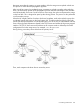
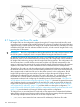
Table Of Contents
- HP Insight Cluster Management Utility v7.2
- Contents
- 1 Overview
- 2 Installing and upgrading HP Insight CMU
- 2.1 Installing HP Insight CMU
- 2.1.1 Management node hardware requirements
- 2.1.2 Disk space requirements
- 2.1.3 Support for non-HP servers
- 2.1.4 Planning for compute node installation
- 2.1.5 Firmware upgrade requirements
- 2.1.6 Configuring the local smart array card
- 2.1.7 Configuring the management cards
- 2.1.8 Configuring the BIOS
- 2.2 Preparing for installation
- 2.3 Installation procedures
- 2.4 Installing HP Insight CMU with high availability
- 2.5 Upgrading HP Insight CMU
- 2.5.1 Upgrading to v7.2 important information
- 2.5.2 Dependencies
- 2.5.3 Stopping the HP Insight CMU service
- 2.5.4 Upgrading Java Runtime Environment
- 2.5.5 Removing the previous HP Insight CMU package
- 2.5.6 Installing the HP Insight CMU v7.2 package
- 2.5.7 Installing your HP Insight CMU license
- 2.5.8 Restoring the previous HP Insight CMU configuration
- 2.5.9 Configuring the updated UP Insight CMU
- 2.5.10 Starting HP Insight CMU
- 2.5.11 Deploying the monitoring client
- 2.6 Saving the HP Insight CMU database
- 2.7 Restoring the HP Insight CMU database
- 2.1 Installing HP Insight CMU
- 3 Launching the HP Insight CMU GUI
- 4 Defining a cluster with HP Insight CMU
- 5 Provisioning a cluster with HP Insight CMU
- 5.1 Logical group management
- 5.2 Autoinstall
- 5.3 Backing up
- 5.4 Cloning
- 5.5 Node static info
- 5.6 Rescan MAC
- 5.7 HP Insight CMU image editor
- 5.8 HP Insight CMU diskless environments
- 5.8.1 Overview
- 5.8.2 The system-config-netboot diskless method
- 5.8.2.1 Operating systems supported
- 5.8.2.2 Installing the operating system on the management node and the golden node
- 5.8.2.3 Modifying the TFTP server configuration
- 5.8.2.4 Populating the HP Insight CMU database
- 5.8.2.5 Creating a diskless image
- 5.8.2.6 Creating a diskless logical group
- 5.8.2.7 Adding nodes into the logical group
- 5.8.2.8 Booting the compute nodes
- 5.8.2.9 Understanding the structure of a diskless image
- 5.8.2.10 Customizing your diskless image
- 5.8.2.11 Best practices for diskless clusters
- 5.8.3 The HP Insight CMU oneSIS diskless method
- 5.8.3.1 Operating systems supported
- 5.8.3.2 Enabling oneSIS support
- 5.8.3.3 Preparing the HP Insight CMU management node
- 5.8.3.4 Preparing the golden node
- 5.8.3.5 Capturing and customizing a oneSIS diskless image
- 5.8.3.6 Manage the writeable memory usage by the oneSIS diskless clients
- 5.8.3.7 Adding nodes and booting the diskless compute nodes
- 5.8.4 Scaling out an HP Insight CMU diskless solution with multiple NFS servers
- 6 Monitoring a cluster with HP Insight CMU
- 6.1 Installing the HP Insight CMU monitoring client
- 6.2 Deploying the monitoring client
- 6.3 Monitoring the cluster
- 6.4 Stopping HP Insight CMU monitoring
- 6.5 Customizing HP Insight CMU monitoring, alerting, and reactions
- 6.5.1 Action and alert files
- 6.5.2 Actions
- 6.5.3 Alerts
- 6.5.4 Alert reactions
- 6.5.5 Modifying the sensors, alerts, and alert reactions monitored by HP Insight CMU
- 6.5.6 Using collectl for gathering monitoring data
- 6.5.7 Monitoring GPUs and coprocessors
- 6.5.8 Monitoring HP Insight CMU alerts in HP Systems Insight Manager
- 6.5.9 Extended metric support
- 7 Managing a cluster with HP Insight CMU
- 7.1 Unprivileged user menu
- 7.2 Administrator menu
- 7.3 SSH connection
- 7.4 Management card connection
- 7.5 Virtual serial port connection
- 7.6 Shutdown
- 7.7 Power off
- 7.8 Boot
- 7.9 Reboot
- 7.10 Change UID LED status
- 7.11 Multiple windows broadcast
- 7.12 Single window pdsh
- 7.13 Parallel distributed copy (pdcp)
- 7.14 User group management
- 7.15 HP Insight firmware management
- 7.16 Customizing the GUI menu
- 7.17 HP Insight CMU CLI
- 8 Advanced topics
- 9 Support and other resources
- A Troubleshooting
- HP Insight CMU manpages
- cmu_boot(8)
- cmu_show_nodes(8)
- cmu_show_logical_groups(8)
- cmu_show_network_entities(8)
- cmu_show_user_groups(8)
- cmu_show_archived_user_groups(8)
- cmu_add_node(8)
- cmu_add_network_entity(8)
- cmu_add_logical_group(8)
- cmu_add_to_logical_group_candidates(8)
- cmu_add_user_group(8)
- cmu_add_to_user_group(8)
- cmu_change_active_logical_group(8)
- cmu_change_network_entity(8)
- cmu_del_from_logical_group_candidates(8)
- cmu_del_from_network_entity(8)
- cmu_del_archived_user_groups(8)
- cmu_del_from_user_group(8)
- cmu_del_logical_group(8)
- cmu_del_network_entity(8)
- cmu_del_node(8)
- cmu_del_snapshots(8)
- cmu_del_user_group(8)
- cmu_console(8)
- cmu_power(8)
- cmu_custom_run(8)
- cmu_clone(8)
- cmu_backup(8)
- cmu_scan_macs(8)
- cmu_rescan_mac(8)
- cmu_mod_node(8)
- cmu_monstat(8)
- cmu_image_open(8)
- cmu_image_commit(8)
- cmu_config_nvidia(8)
- cmu_config_amd(8)
- cmu_config_intel(8)
- cmu_mgt_config(8)
- cmu_firmware_mgmt(8)
- cmu_monitoring_dump(8)
- cmu_rename_archived_user_group(8)
- Glossary
- Index
8.5 Support for ScaleMP
HP Insight CMU can be integrated to work with ScaleMP. To enable support for ScaleMP, add the
following variable and setting to the /opt/cmu/etc/cmuserver.conf file:
CMU_vSMP_PREFIX=vSMP_
This setting configures the prefix that is used to identify HP Insight CMU logical group nodes that
can be pxe-booted into the virtual SMP environment. The images that are associated with these
logical groups can be created with normal HP Insight CMU methods (such as autoinstall and
cloning), or made diskless. The ScaleMP support is activated when nodes that are active members
of a logical group named "vSMP_*" are pxe-booted.
If a logical group named "vSMP_*" is a diskless image, then those nodes pxe-boot the diskless
image into the virtual SMP environment.
If a logical group named "vSMP_*" is a disk-based image, then those nodes must be actively
pxe-booted by selecting network boot in the boot menu.
The first node listed as "active" in the logical group named "vSMP_*" is the primary node in the
virtual SMP environment. The remaining nodes are the secondary nodes.
For more details, see the ScaleMP documentation.
8.6 Cloning mechanisms
The cloning process requires you to create logical groups. A logical group is a collection of nodes
that share the same operating system image. Each logical group is defined under the /opt/cmu/
image directory on the image server. This directory contains the target system disk partition
information and compressed image of the selected partitions from a master disk. The backup utility
provides a mechanism to backup the master disk image of the logical group of a node.
A logical group can contain nodes from one or more network entities. By default, HP Insight CMU
puts all nodes in the default logical group. HP Insight CMU supports multiple logical groups for a
cluster. This enables the cluster to be configured to meet the needs of several user types. A logical
group can only contain nodes of similar server machines because they share the same operating
system image.
A cluster of nodes generally has several racks. Each rack has one Ethernet switch. For the best
network performance during cloning, all nodes belonging to a single rack must be configured in
an HP Insight CMU network entity. When you clone a group of nodes belonging to different network
entities, one node per network entity is elected as the secondary server. Only one secondary server
exists in each network entity. A copy of the TFTP root directory and the cloning database is
transferred to each secondary server. All secondary servers boot in a pipeline on the primary server
and each one of these servers must boot between 1 (0) and 64 (63) compute nodes.
The TFTP root directory is stored in memory (ramdrive) on each secondary server and on the hard
drive for the primary server which is usually the HP Insight CMU management node. The TFTP root
directory of the HP Insight CMU management node is shared among all the secondary servers.
The TFTP directory of each secondary server is shared among all nodes of the network entity of
the secondary server.
When a node is booted, it mounts the local system disk and checks the partitions against the clone
image partition information. If the descriptions differ, the node changes the local disk partition and
rebuilds file systems. When the partitioning is correct, each node waits for the clone image to
download. In the first part of the propagation, only secondary servers are enabled to receive the
clone image.
When all secondary servers own a copy of the clone image, the primary server stops the
propagation and each secondary server pushes its clone image to all nodes in the network entity.
The transfer uses TCP/IP sockets. The clone image is saved to the local disk. The node then asks
the image server if any successors are waiting for upload. If any successors are waiting, the node
148 Advanced topics