
Setup and Install

Installing HyperFabric
Installing HyperFabric Switches
Chapter 3
80
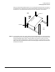
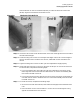
NOTE HP recommends employing two people to support the weight of the switch because
End-A of the rail is not yet secured.
Step 8. Secure the switch and End-A of each rail by aligning the two holes in each flange with
the two holes in each rack column, and two of the holes in each rail. Secure the entire
assembly with two screws in each flange.
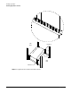
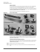
Step 9. Attach the cable from the corresponding adapter for each port that is connected to a
HyperFabric adapter in an HP 9000 system.
NOTE Your connections must be copper-to-copper and fibre-to-fibre (including cables).
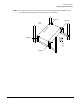
Step 10. Connect the switch to the Ethernet network.
Step 11. Plug the switch’s power cord in to the rack’s Power Distribution Unit (PDU), if it has
one.
NOTE Ensure that you plug a power card that is compatible with your country’s specifications
in to a power strip or outlet that you want to use for the switch. In such a scenario, you
are responsible for obtaining a compatible power cord.
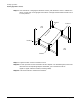
Step 12. Power on the HF2 switch by plugging the power cord into the AC inlet on the back of the
switch. (There is no power switch.)
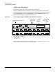
Step 13. Once the power is on, check these LEDs on the integrated Ethernet management LAN
adapter card in the top slot of the switch:
✓ The “Operating/Fault” LED shows solid green.
✓ The “Power A” and “Power B” LEDs show solid green.
✓ The “Ethernet Port Main” and “Ethernet Port Aux” LEDs show solid green
(connected) or flashing green. This indicates that ethernet traffic is flowing to the
switch. For information about locating the LEDs, see Figure 3-3 on page 76 or
Figure 3-4 on page 77.
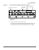
Step 14. On the integrated 8-port fibre card in the middle slot of the switch, check whether the
LED for each switch port that is connected to an HF2 adapter shows solid green. If the
LED shows solid green, it means the connection is operational.
Step 15. On the switch module in the expansion slot in the bottom slot of the switch, check
whether the LED for each switch port that is connected to an HF2 adapter shows solid
green. If the LED shows solid green, it means the connection is operational.
For more information about the switch’s LEDs, see “HF2 Switch LEDs” on page 118.
Repeat steps 1 to 16 to install another HF2 switch using the rail kit. For information
about installing an HF2 switch without using a rail kit, see “Without the Rail Kit” on
page 81.