
Setup and Install

Installing HyperFabric
Installing HyperFabric Switches
Chapter 3
75
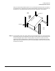
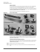
Step 12. Plug the switch’s power cord into the rack’s power distribution unit (PDU), if it has one.
Alternatively, you can plug a power cord that is compatible with your country’s
requirements into a power strip or outlet that you want to use for the switch. (In this
case, you are responsible for obtaining a compatible power cord.)
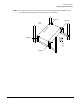
Step 13. Power on the HF1 switch by plugging the power cord into the AC inlet on the back of the
switch. (There is no power switch.) Once the power is on, the “Power” LED shows solid
green.
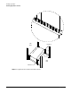
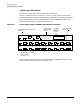
Step 14. Check that, for each HF1 switch port that is connected to an HF1 adapter, the LED on
the port shows as solid green (see Figure 3-2 on page 68). This means the connection is
operational.
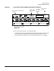
Step 15. Check that the “Ethernet” LED on the switch’s Ethernet port is showing solid green
(connected) or flashing green (Ethernet traffic is flowing to the switch). See Figure 3-2 on
page 68 for the location of the LED.
For more detailed information about the switch’s LEDs, see “HF1 Switch LEDs” on
page 114.
Step 16. If you want to install another HF1 switch, go back to step 1.
Otherwise, go to step 17.
Step 17. If you want to install one or more HF2 switches, go to the next section, “Installing the
HF2 Switch”.
Otherwise, go to Chapter 4, “Configuring HyperFabric,” on page 83.