
Installation Manual


29
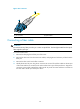
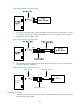
Figure 33 SFP+ transceiver module
Fiber cable overview
CAUTION:
• Never exert a fierce force when you insert or remove a fiber connector.
• Never pull, press or extrude the fiber fiercely.
Optical fibers can be classified into single-mode optical fibers and multi-mode optical fibers. A
single-mode optical fiber carries only a single ray of light, and a multi-mode optical fiber carries multiple
modes of lights.
Table 9 Characteristics of single-mode and multi-mode optical fibers
Item Sin
g
le-mode o
p
tical
fiber
Multi-mode o
p
tical fiber
Core Small core (10 micrometers or less)
Larger core than single-mode
optical fiber (50 micrometers, 62.5
micrometers or greater)
Dispersion Less dispersion
Allows greater dispersion and
therefore, signal loss exists
Light source and transmission
distance
Users lasers as the light source often
within campus backbones for distance
of several thousand meters
Uses LEDs as the light source often
within LANs or distances of a
couple hundred meters within a
campus network
Table 10 lists the allowed maximum tensile load and crush load for the fiber.
Table 10 Allowed maximum tensile force and crush load
Period of force Tensile load (N)
Crush load (N/mm)
Short period 150 500
Long term 80 100
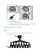
Fiber connectors are indispensable passive components in an optical fiber communication system. They
allow the removable connection between optical channels, which makes the optical system debugging
and maintenance more convenient. There are multiple types of fiber connectors. Figure 34 sh
ows an LC
connector. Fiber ports of the HP HSR6800 routers support only LC connectors.