
Installation Manual


20
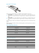
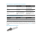
Figure 22 RJ-45 connector pinout
EIA/TIA cabling specifications define two standards, 568A and 568B, for cable pinouts.
• Standard 568A—Pin 1: white/green stripe, pin 2: green solid, pin 3: white/orange stripe, pin 4:
blue solid, pin 5: white/blue stripe, pin 6: orange solid, pin 7: white/brown stripe, pin 8: brown
solid.
• Standard 568B—Pin 1: white/orange stripe, pin 2: orange solid, pin 3: white/green stripe, pin 4:
blue solid, pin 5: white/blue stripe, pin 6: green solid, pin 7: white/brown stripe, pin 8: brown
solid.
Ethernet twisted pair cables can be classified into straight-through and crossover cables based on their
pinouts
For the pinouts of the twisted pair cables, see the following tables. (A and B represent the two ends of a
cable, respectively.)
Table 7 Straight-through cable pinouts
Pinout No. A B
1 Orange/white Orange/white
2 Orange Orange
3 Green/white Green/white
4 Blue Blue
5 Blue/white Blue/white
6 Green Green
7 Brown/white Brown/white
8 Brown Brown
Table 8 Crossover cable pinouts
Pinout No. A B
1 Orange/white Green/white
2 Orange Green
3 Green/white Orange/white
4 Blue Blue
5 Blue/white Blue/white
6 Green Orange
PIN #8
PIN #1