HP StorageWorks XP24000 Disk Array Site Preparation Guide Part number: AE131-96002 First edition: June 2007
Legal and notice information © Copyright 2007 Hewlett-Packard Development Company, L.P. The information contained herein is subject to change without notice. The only warranties for HP products and services are set forth in the express warranty statements accompanying such products and services. Nothing herein should be construed as constituting an additional warranty. HP shall not be liable for technical or editorial errors or omissions contained herein.
Contents About this guide ................................................................................... 9 Intended audience ...................................................................................................................... 9 Related documentation ................................................................................................................ 9 Document conventions and symbols ...........................................................................................
Altitude ............................................................................................................................. Air conditioning ................................................................................................................. Temperature specifications ................................................................................................... Humidity specifications ...............................................................................................
4 Delivery and unpacking for the HP XP24000 Disk Array ....................... 61 Checking for shipping shortage and damage ............................................................................... Unpacking the equipment .......................................................................................................... Packaging configurations .................................................................................................... Required personnel ................................
Figures 1..XP24000 frame layout ............................................................................................ 19 2..Frame dimensions ................................................................................................... 20 3..DKC floor cutout ..................................................................................................... 26 4..DKU floor cutout ..................................................................................................... 26 5..
Tables 1..Document conventions ............................................................................................. 10 2..Site prep team information ....................................................................................... 14 3..Site prep checklist ................................................................................................... 15 4..DKC dimensions ..................................................................................................... 20 5..
About this guide This guide provides information about site preparation and installation of the HP StorageWorks XP24000 Disk Array. Unless otherwise noted, the term disk array refers to the HP StorageWorks XP24000 Disk Array. Intended audience This guide is intended for members of the site preparation team as defined in this document.
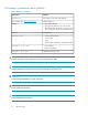
Document conventions and symbols Table 1 Document conventions Convention Element Blue text: Table 1 Cross-reference links and e-mail addresses Blue, underlined text: http://www.hp.
Conventions for storage capacity values Use the following values to calculate physical storage capacity (hard disk drives) for HP XP storage systems: • 1 KB (kilobyte) = 1,000 bytes • 1 MB (megabyte) = 1,0002 bytes • 1 GB (gigabyte) = 1,0003 bytes • 1 TB (terabyte) = 1,0004 bytes Use the following values to calculate logical storage capacity (logical devices) for HP XP storage systems: • 1 KB (kilobyte) = 1,024 bytes • 1 MB (megabyte) = 1,0242 bytes • 1 GB (gigabyte) = 1,0243 bytes • 1 TB (terabyte) = 1,024
Customer self repair HP customer self repair (CSR) programs allow you to repair your StorageWorks product. If a CSR part needs replacing, HP ships the part directly to you so that you can install it at your convenience. Some parts do not qualify for CSR. Your HP-authorized service provider will determine whether a repair can be accomplished by CSR. For more information about CSR, contact your local service provider. For North America, see the CSR website: http://www.hp.
1 Site prep team and tasks for the HP XP24000 Disk Array The objective of a site prep is to prepare your site for the successful and timely installation of this HP product. Proper site preparation is vital for the reliability of the disk array. Site preparation involves a careful balance of equipment design criteria, site environmental variables, your business needs, and your budget constraints. In addition to this guide, other site prep resources may be available to you.
1. If you have not printed a copy of this guide, print the following “Site prep checklist” and Chapter 2. Working from printed copies makes it easier to use the tools provided and provides hard copy documents that you can keep for your records. 2. Carefully review Chapter 2 to understand the site requirements for the disk array. If you plan to connect additional external storage, be sure to take the requirements of that storage into account. See the documentation for the external system. 3.
Table 3 Site prep checklist Checklist questions Yes No Reference Is there a fire protection system in the computer room? “Fire safety” on page 23 Is the computer room free of any equipment servicing hazards (for example, electrical or data cables that obstruct access)? “Equipment servicing hazards” on page 23 Is the existing floor plan documented? “The space planning process” on page 27 Has a new floor plan been developed to include the new array? “The space planning process” on page 27 Does the
Checklist questions Yes No Reference Does the computer room support other environmental considerations (such as vibration and acoustics)? “Vibration specifications” on page 35 Are two AC outlets, on different lines, available for the equipment? “Electrical requirements” on page 42 Does the input voltage correspond to the DKC and DKU equipment specifications? “Line voltage” on page 42 Are the input circuit breakers adequate for equipment loads? “Branch circuit breakers” on page 42 Does the input
• Making building alterations • Placing an order for data communication equipment, including equipment required to support the internet-based remote support option The time between placing an equipment order and actual delivery can vary. Contact your HP representative to determine the best estimated delivery dates.
Site prep team and tasks for the HP XP24000 Disk Array
2 Site requirements for the HP XP24000 Disk Array Your site must meet the following requirements before HP can deliver and install the system.
• • • • One One One One DKC DKC DKC DKC and and and and one DKU (R1) two DKUs (R1 and R2 or R1 and L1) three DKUs (R1, R2, and L1 or R1, L1, and L2) four DKUs (maximum configuration) Dimensions Dimensions for the DKC and DKU are given below. Use the packaged values in the tables when determining delivery space requirements and unpackaged values for space planning. DKC unpackaged width includes two side panels each 1.6 cm (0.63 in.) wide.
Table 5 DKU dimensions Dimension DKU unpackaged DKU packaged cm in cm in Width 65 25.6 95 37.4 Depth 92.5 36.42 111 43.7 Height 192 75.6 209 82.3 Weights Use the approximate packaged weights when determining delivery requirements, and unpackaged weights to calculate the total weight of your configuration. Plan your facility to accommodate the weight of the maximum configuration for each DKC and DKU even if you expect to start with an empty cabinet and add components later.
Delivery space requirements The delivery area must provide enough space and floor strength to support the packaged equipment cartons for the disk array. Refer to the preceding packaged dimensions and the packaged weights. CAUTION: Make sure that your doorways and hallways provide enough clearance to move the equipment safely from the delivery area to the computer room. Permanent obstructions such as pillars or narrow doorways can cause equipment damage. If necessary, plan for the removal of walls or doors.
the act of removing the paper from its box generates static. To allow the static to discharge gradually over time, leave the box open in the computer room for several hours before use. Follow these precautions to minimize possible ESD-induced failures in your computer room: • • • • • • • • Install conductive flooring (conductive adhesive must be used when laying tiles). Use conductive wax if waxed floors are installed.
Raised floor requirements The computer room floor must be able to support the total weight of the equipment as well as localized weight at each caster or foot of the equipment cabinets. A common method of preparing an adequate floor for a computer room is to construct a raised floor over the building floor.
CAUTION: If your computer room has carpeting, place static discharge mats so that personnel must walk across them before touching any part of the array. Failure to comply with this precaution can result in equipment damage through static discharge. Floor cutouts The following figures show the locations of floor cutouts under the DKC and DKU for cabling. Position floor cutouts toward the center of the cabinet.
Figure 3 DKC floor cutout Figure 4 DKU floor cutout 26 Site requirements for the HP XP24000 Disk Array
Space planning requirements Space planning requires making sure your computer room: • Is large enough to hold the new array and other equipment and furniture • Provides minimum clearance around the array for service access and weight distribution on the floor • Includes correctly positioned floor cutouts for feeding power and data cables through the floor to the array The space planning process 1. Document your computer room's existing floor plan, including the locations of: 2.
2. • • • • • In DKC floor clearance on page 29 DKC and one DKU floor clearance on page 30 DKC and two DKUs floor clearance on page 31 DKC and three DKUs floor clearance on page 32 DKC and four DKUs floor clearance on page 33 the floor clearance diagram: a. Clearance “A” is the space between the service clearance at the left side of the array (10 cm minimum for installing the kickplate) and any other object, such as a desk or wall. b.
DKC floor clearance Figure 5 Floor clearances, DKC only Table 9 Floor clearances, DKC only Floor load rating (kg/m2) If C=0 A+B= If C=20 cm (7.9 in) A+B= If C=40 cm (15.8 in) A+B= If C=60 cm (23.6 in) A+B= If C=100 cm (39.
DKC and one DKU floor clearance Figure 6 Floor clearances, DKC and one DKU Table 10 Floor clearances, DKC and one DKU Floor load rating (kg/m2) If C=0 A+B= If C=20 cm (7.9 in) A+B= If C=40 cm (15.8 in) A+B= If C=60 cm (23.6 in) A+B= If C=100 cm (39.
DKC and two DKUs floor clearance Figure 7 Floor clearances, DKC and two DKUs NOTE: The clearance diagram shows a typical configuration. Other configurations are possible. Consult your HP representative for help with equipment arrangements that differ from the one shown. Table 11 Floor clearances for DKC and two DKUs Floor load rating (kg/m2) If C=0 A+B= If C=20 cm (7.9 in) A+B= If C=40 cm (15.8 in) A+B= If C=60 cm (23.6 in) A+B= If C=100 cm (39.
DKC and three DKUs floor clearance Figure 8 Floor clearance, DKC and three DKUs NOTE: The clearance diagram shows a typical configuration. Other configurations are possible. Consult your HP representative for help with equipment arrangements that differ from the one shown. Table 12 Floor clearance, DKC and three DKUs Floor load rating (kg/m2) If C=0 A+B= If C=20 cm (7.9 in) A+B= If C=40 cm (15.8 in) A+B= If C=60 cm (23.6 in) A+B= If C=100 cm (39.
DKC and four DKUs floor clearance Figure 9 Floor clearances, DKC and four DKUs Table 13 Floor clearances, DKC and four DKUs Floor load rating (kg/m2) If C=0 A+B= If C=20 cm (7.9 in) A+B= If C=40 cm (15.8 in) A+B= If C=60 cm (23.6 in) A+B= If C=100 cm (39.
Altitude The maximum altitude for system operation is 3,000 meters (9,842 feet). The minimum altitude for system operation is –60 meters (–197 feet). Air conditioning Use separate computer room air conditioning duct work. If it is not separate from the rest of the building, it might be difficult to control cooling and air pressure levels. Duct work seals are important for maintaining a balanced air conditioning system and high static air pressure.
Table 15 Humidity specifications Humidity range type Noncondensing relative humidity (RH) Recommended operating humidity range 50% to 55% at 22 degrees C (71 degrees F) Operating humidity range 20% to 80% at 22 degrees C (71 degrees F) Nonoperating humidity range 8% to 90% Shipping and storage humidity range 5% to 95% (product packed in factory packing) Operating maximum wet bulb temperature 26 degrees C, 79 degrees F Nonoperating maximum wet bulb temperature 27 degrees C, 81 degrees F Shippin
Table 17 Shock specifications Condition Specification Operating None Nonoperating 8 G, 15 ms Shipping and storage (in factory packing) Horizontal, incline impact: 1.22 m/s Vertical, rotational edge: 0.15 m Acoustics The acoustic emission specifications for the disk array are: • 8.
Table 19 Air flow specifications Product number Description Air flow (cubic meters/minute) AE131A HP XP24000 Disk Control Frame (DKC) 34 HP XP24000 Disk Array Frame (DKU) 32 AE173A Component heat, power, and weight specifications The following table lists heat, power, and weight specifications for individual components. By adding the specifications for each component in your system, you can determine approximate totals for your specific system.
Table 20 Component heat, power, and weight specifications Product Number Description Heat Output (kW) Power (kVA) Weight (kg/lbs) AE131A HP XP24000 DKC Disk Control Frame 0.834 0.860 476/1049 #001 3P/30A/60Hz 3760PDG/115J-AP8508 2 Cords n/a n/a 9.20/20.28 #002 3P/30A/50Hz No Plugs 2 Cords n/a n/a 7.10/15.65 #003 1P/50A/60Hz 9P53U2 2 Cords n/a n/a 8.70/19.18 #004 1P/50A/50Hz No Plugs 2 Cords n/a n/a 6.80/14.99 #005 1P/30A/60Hz 3750DP 4 Cords n/a n/ 9.00/19.
Product Number Description Heat Output (kW) Power (kVA) Weight (kg/lbs) AE153A HP XP24000 4 GB Cache Memory 0.015 0.015 0.08/0.18 AE155A HP XP24000 Shared Memory Adapter 0.005 0.005 1.20/2.65 AE156A HP XP24000 2 GB Shared Memory 0.013 0.013 0.08/0.18 AE157A HP XP24000 4 GB Shared Memory 0.013 0.013 0.08/0.18 AE160A HP XP24000 DKC 12V Battery 0.029 0.030 14.00/30.86 AE161A HP XP24000 DKC/DKU 56V Battery 0.128 0.132 36.00/79.37 AE162A HP XP24000 Cache Switch 0.029 0.
Product Number Description Heat Output (kW) Power (kVA) Weight (kg/lbs) 1P/30A/50Hz No Plugs 4 Cords n/a n/a 7.10/15.65 AE174A HP XP24000 DKU Disk Expansion Kit 0.291 0.300 37.70/83.11 AE176A HP XP24000 73GB 15k rpm Array Group 0.080 0.084 3.60/7.94 AE177A HP XP24000 146GB 15k rpm Array Group 0.080 0.084 3.60/7.94 AE178A HP XP24000 300GB 10k rpm Array Group 0.080 0.084 3.60/7.94 AE176AS HP XP24000 73GB 15k rpm Spare Disk 0.020 0.021 0.90/1.
Although this problem is relatively rare, it may be an issue within your computer room. Since metallic contamination can cause permanent or intermittent failures on your electronic equipment, HP strongly recommends that your site be evaluated for metallic particulate contamination before installation of electronic equipment. Data communication requirements Route data communication cables away from areas of high static electric fields created by power transformers and heavy foot traffic.
The C-Track solution offers an internet connectivity option for the XP24000 in addition to a modem connectivity option. If you choose the internet-based remote support solution, additional infrastructure and site preparation are required. This additional preparation may include server and router requirements, and HP and the customer may both have implementation responsibilities. For more information about the C-Track internet-based solution, ask your HP representative.
Safety and dedicated ground The primary reason for earth grounding electrical systems is safety. The safety ground is required by the National Electric Code (USA) and most other local, regional, and national codes. In addition to safety ground, HP requires that a dedicated (earth reference) ground be installed as a common reference point for all system components. Consult with an HP representative and your electrician to ensure that your electrical system meets all local and national safety codes.
Fault tolerant AC power examples Figure 10 Fault tolerant AC wiring diagram When receptacles are used to connect disk array components to AC power, they must include a dedicated ground connection that is insulated from the receptacle. It is important that the receptacle box be grounded with an additional ground connection that is separate from the dedicated ground. The additional ground can be hard conduit.
If necessary, an HP representative can measure your power line noise level and make appropriate recommendations concerning the use of line treatment devices. UPS Most disk array units are installed in data centers where an uninterruptible power supply (UPS) strategy is already in place. However, if you are making your first large disk array purchase, you may need a separate UPS solution. CAUTION: This section discusses a product UPS.
Site requirements for the HP XP24000 Disk Array
3 Electrical specifications for the HP XP24000 Disk Array The detailed electrical specifications in this chapter are provided to help your site electrician perform any necessary electrical work related to site prep. AC line voltage requirements Power specifications are presented in the following tables. Please note that in all tables 208 VAC is 60 Hz only. Units with only two power cords require only two circuit breakers.
30-amp, 50 or 60 Hz, single-phase DKC Table 24 DKC power specifications, 30-amp, 50 or 60 Hz, single-phase Parameter Minimum 200 VAC 50 or 60 Hz 208 VAC 60 Hz only 220 VAC 50 Hz only 230 VAC 50 or 60 Hz 240 VAC 50 Hz only 184 191 202 212 221 212 220 233 244 254 9.10 8.77 8.29 7.9 7.
30-amp, 50 or 60 Hz, three-phase DKC Table 25 DKC power specifications, 30-amp, 50 or 60 Hz, three-phase Parameter Minimum 200 VAC 50 or 60 Hz 208 VAC 60 Hz only 220 VAC 50 Hz only 230 VAC 50 or 60 Hz 240 VAC 50 Hz only 380 VAC 50 Hz only 400 VAC 50 Hz only 415 VAC 50 Hz only 184 191 202 212 221 350 368 382 212 220 233 244 254 403 424 440 10.5 10.1 9.59 9.13 8.76 5.53 5.26 5.
-amp, 50 or 60 Hz, single-phase DKU Table 26 DKU power specifications, 50-amp, 50 or 60 Hz, single-phase Parameter Minimum 200 VAC 50 or 60 Hz 208 VAC 60 Hz only 220 VAC 50 Hz only 230 VAC 50 or 60 Hz 240 VAC 50 Hz only 184 191 202 212 221 212 220 233 244 254 17.8 17.2 16.2 15.5 14.
30-amp, 50 or 60 Hz, single-phase DKU Table 27 DKU power specifications, 30-amp, 50 or 60 Hz, single-phase Parameter Minimum 200 VAC 50 or 60 Hz 208 VAC 60 Hz only 220 VAC 50 Hz only 230 VAC 50 or 60 Hz 240 VAC 50 Hz only 184 191 202 212 221 212 220 233 244 254 8.91 8.59 8.12 7.74 7.
30-amp, 50 or 60 Hz, three-phase DKU Table 28 DKU power specifications, 30-amp, 50 or 60 Hz, three-phase Parameter Minimum 200 VAC 50 or 60 Hz 208 VAC 60 Hz only 220 VAC 50 Hz only 230 VAC 50 or 60 Hz 240 VAC 50 Hz only 380 VAC 50 Hz only 400 VAC 50 Hz only 415 VAC 50 Hz only 184 191 202 212 221 350 368 382 212 220 233 244 254 403 424 440 10.3 9.12 9.39 8.94 8.58 5.42 5.15 4.
Russellstoll connectors are available through most electrical distributors. HP has arranged for the distributors listed below to stock these connectors. These distributors are able to ship worldwide via your preferred carrier. Beck Electrical Supply, 2775 Goodrick Avenue, Richmond, CA 94801. USA Telephone: (800) 466-4395. Fax: (800) 466-5442. Contact: Ken Mogan, casales@beckelectric.com. Website: http://beckelectric.com/store/index.php Source Research, Inc.
Figure 11 30-amp, three-phase power cords If one power source malfunctions, the other power source assumes the total load, providing uninterrupted operation. HP recommends that each power cord have a separate electrical circuit as its source, in case of a circuit failure. Each power-supply cord is supplied with an attachment plug type Russellstoll 3760PDG.
Connecting the power-supply cords (Europe) All 50 Hz, European HP XP24000 disk array cabinets are shipped with unterminated power cords. Your electrician must select and install the correct power plug. Be sure to prepare the socket receptacles and power cords between the power distribution board of the building and the attachment plugs for the unit. 30-amp power cords of type H07RN-F or equivalent, with five 6 square mm conductors per cord, are provided with the unit.
Single-phase AC cabling for the USA When configured for 50-amp, single-phase power, each XP24000 disk array cabinet has two power cords and two main disconnect devices so that AC power can be supplied from separate power distribution panels. When configured for 30-amp, single-phase power, each HP XP24000 disk array cabinet has four power cords and four main disconnect devices. CAUTION: An HP representative should be present whenever the disk array is being connected to a new power source for the first time.
Figure 14 Connecting 30-amp, single-phase power cords Be sure to install Russellstoll 3933 (alternate, 9C33U0) or 3753 (alternate, 9R33U0W) socket receptacles between the power distribution panel of the building and the power plugs for the unit. The power cords provided with the disk array are nonshielded, type ST or equivalent with three #10 AWG (minimum) conductors terminated at one end with an assembled plug connector.
Connecting the power-supply cords (Europe) 50-amp single phase power cords for Europe Each 50-amp HP XP24000 disk array cabinet has two power-supply cords. The power cords included with the unit are type H07RN-F or equivalent with three 10 square mm conductors. CAUTION: Be sure to connect the power cords to the distribution panel as shown in the following figure. Improper wiring of the neutral conductor may cause damage to the disk array.
In many cases, local codes do not allow a branch circuit fitted with a 50-amp receptacle or connector to be protected by an overcurrent-protection device with a rating lower than 50 amps. You can order an HP XP24000 disk array with the 30-amp power option to comply with these local codes. Your electrician knows the appropriate code requirements for your location/site.
Electrical specifications for the HP XP24000 Disk Array
4 Delivery and unpacking for the HP XP24000 Disk Array The disk array equipment is shipped directly from HP. If the disk array is part of a system order, HP coordinates shipment from all HP locations so that all of the equipment arrives at your site at approximately the same time. When your equipment ships, HP provides you with carrier information and an expected delivery date. Factors beyond HP's control can cause delivery delays.
within the USA that are direct from the factory to the customer. HP uses special carriers with a dedicated fleet of trucks and specially trained personnel. • Full packaging — consists of a pallet, wooden loading ramp, inner packaging, and outer corrugated carton assembly. • Full packaging with wooden crate — consists of full packaging encased in a wooden crate.
CAUTION: Any movement of the equipment by forklift should be done prior to unpacking. The carton assembly provides the most secure support of the equipment during movement. Transporting the equipment by forklift after the packaging carton has been removed is not advisable. CAUTION: The equipment cabinets are top heavy and contain very sensitive electronic and mechanical components.
Figure 16 Removing packing materials 2. Cut and remove the polyester bands (item 1 in the illustration). 3. Remove the nails attaching the carton to the pallet (item 2). 4. Remove the plastic carton fasteners (item 3). 5. Remove the carton. 6. Remove the accessory boxes, ramp, and corner pads (items 4, 5, and 6 in the following illustration).
Figure 17 Unpacking procedure 7. Using a 6 mm hex and 19 mm wrench, remove the adapter plates that anchor the cabinet to the pallet (item 7). 8. Remove the poly bag covering the cabinet (item 8). 9. Following the instructions provided on the wooden ramp, attach the ramp to the pallet and roll the cabinet onto the floor. 10. Visually check the unit for any damage. If any damage is visible, report it immediately to HP and the shipping carrier.
Delivery and unpacking for the HP XP24000 Disk Array
Glossary for the HP XP24000 Disk Array AL Arbitrated loop. AL-PA Arbitrated loop physical address. allocation The ratio of allocated storage capacity versus total capacity as a percentage. “Allocated storage” refers to those LDEVs that have paths assigned to them. The allocated storage capacity is the sum of the storage of these LDEVs. Total capacity refers to the sum of the capacity of all LDEVs on the disk array. array group A group of four identical unformatted disk drives (HDDs).
Therefore, to uniquely identify a particular LDEV requires both the CU number and the LDEV number. CU Control unit. CVS Custom volume size. CVS devices (OPEN-x CVS) are custom volumes configured using array management software to be smaller than normal fixed-size OPEN system volumes. Synonymous with volume size customization (VSC). disk adapter (DKA) The disk adapter passes data between the cache and the physical drives. disk unit (DKU) The array hardware that houses the disk array physical disks.
FICON IBM mainframe Fiber Optic Connection. GB Gigabytes. GLM Gigabyte link module. HA High availability. HBA Host bus adapter. A built-in function or a card installed in a PC or other host computer to enable connection of the host to the SAN. host mode Each port can be configured for a particular host type. These modes are represented as two-digit hexadecimal numbers. For example, host mode 08 represents an HP-UX host.
mutual hot standby system Two servers that are poised to cover for each other if necessary. NAS Network attached storage. node Logically speaking, an environment where instances can be executed. Physically, a processor, which is an element of a cluster system. NVS Nonvolatile storage. OFC Open Fibre Control. OLM Optical link module. OS Operating system. PA Physical address. parity group A parity group is a disk configuration in which multiple disks work together to provide redundancy.
RAID Manager HP StorageWorks XP RAID Manager software, a command line interface for managing XP disk arrays. R-SIM Remote service information message. R/W, r/w Read/write. script file A file containing a shell script. SCSI Small computer system interface. shell script A command sequence executed by a UNIX shell. sidefile An area of cache used to store the data sequence number, record location, record length, and queued control information. SIM Service information message.
Glossary for the HP XP24000 Disk Array
Index A AC line voltage, 42, 47 acoustics, 36 air conditioning, 34 and dust control, 40 and metallic particulate contamination, 40 air pressure, 22, 40 airborne contaminants, 40 altitude, 34 antistatic carpeting, 24 containers, 23 audience, 9 B branch circuit requirements, 54, 55, 57, 58 branch circuits, 42 building codes, 22, 23, 43, 43 C C-Track, 9, 41, 42 cabinet stability, 11 cables, 27 and mechanical vibration, 35 and raised floors, 24 as safety hazards, 23 Cat 5, 41 floor cutouts for, 25 in floor pl
E earth ground requirements, 43 electrical interference, 45 electrical requirements, 42 electrical specifications, 47 electromagnetic interference, 45 electrostatic discharge.
P particulate contamination, metallic, 40 phone home, 41 phone line, 41 physical specifications, 19 pollution control, 40 power receptacles, 43 requirements, 42, 47 uninterruptible, 45 consumption, 36 cords, 47, 48, 49, 50, 51, 52 cords, floor cutouts for, 25 cords, single-phase for Europe, 58, 58 cords, single-phase for USA, 56, 57 cords, three-phase for Europe, 55 cords, three-phase for USA, 53, 54 line transients, 44 R raised floor, 24, 27 See also floor, 24 receptacles, 44, 52 receptacles, power, 43 re