HP StorageWorks XP20000 Disk Array Site Preparation Guide Part number: AE190-96002 First edition: September 2007
Legal and notice information © Copyright 2007 Hewlett-Packard Development Company, L.P., all rights reserved. Confidential computer software. Valid license from HP required for possession, use or copying. Consistent with FAR 12.211 and 12.212, Commercial Computer Software, Computer Software Documentation, and Technical Data for Commercial Items are licensed to the U.S. Government under vendor’s standard commercial license. The information contained herein is subject to change without notice.
Contents About this guide . . . . . . . . . . . . . . . . . . . . . . . . . . Intended audience . . . . . . . . Related documentation . . . . . . Document conventions and symbols Rack stability . . . . . . . . . . HP technical support . . . . . . . Subscription service . . . . . . . HP websites . . . . . . . . . . . Documentation feedback . . . . . . . . . . . . . . . . . . . . . . . . . . . . . . . . . . . . . . . . . . . . . . . . . . . . . . . . . . . . . . . . . . . . . . . . . . . . . . . .
Data communication requirements . . . . . . . . . Electrical requirements . . . . . . . . . . . . . . Line voltage . . . . . . . . . . . . . . . . . Branch circuit breakers . . . . . . . . . . . . Single-phase branch circuit breakers . . . . Frequency . . . . . . . . . . . . . . . . . Safety and dedicated ground . . . . . . . . . Grounding requirements . . . . . . . . . . . AC connections . . . . . . . . . . . . . . . Power line transients . . . . . . . . . . . . .
Figures 1 Fully Configured XP20000 Rack . . . . . . . . . . . . . . . . . . . . . . . . . 16 2 Rack Assembly Footprint . . . . . . . . . . . . . . . . . . . . . . . . . . . . .
Tables 1 Document Conventions 6 . . . . . . . . . . . . . . . . . . . . . . . . . . . . . .
About this guide This guide provides information about preparing your site for installation of the HP StorageWorks XP20000 Disk Array. Unless otherwise noted, the term disk array refers to the HP StorageWorks XP20000 Disk Array.
Convention Element Monospace, italic text • Code variables • Command variables Monospace, bold text Monospace, bold text WARNING! Indicates that failure to follow directions could result in bodily harm or death. CAUTION: Indicates that failure to follow directions could result in damage to equipment or data. IMPORTANT: Provides clarifying information or specific instructions. NOTE: Provides additional information. TIP: Provides helpful hints and shortcuts.
• • • • Product model names and numbers Error messages Operating system type and revision level Detailed questions For continuous quality improvement, calls may be recorded or monitored. Subscription service HP strongly recommends that customers register online using the Subscriber’s Choice website: http://www.hp.
About this guide
1 Site preparation team and tasks The objective of a site preparation is to prepare your site for the successful and timely installation of the HP StorageWorks XP20000 disk array. Proper site preparation is vital for the reliability of the disk array. Site prep involves a careful balance of equipment design criteria, site environmental variables, your business needs, and your budget constraints. In addition to this guide, other site prep resources may be available to you.
5. Checklist items that require a “Yes” answer are marked with asterisks (*). If you answer “No” to any of these items, your site does not meet site requirements for the disk array. Using the information in Chapter 2, correct the site environment so that you can answer “Yes” for each of these items. 6. When your site meets all site requirements, contact your HP Service Representative to coordinate delivery of the disk array equipment. 7.
Is a telephone line available for HP representative use? Data comm requirements, page 28 Is a private LAN available? Data comm requirements, page 28 * Can the temperature be maintained between 16 and 32 degrees C? Temperature specifications, page 25 * Can temperature changes be held to less than 10 degrees C per hour? Temperature specifications, page 25 * Can the humidity level be maintained between 20% and 80%? Humidity specifications, page 25 * Is the computer room protected against dust, pollu
Site preparation time allowances The following site prep tasks may require several weeks: • • • • • Acquiring required power connectors Arranging for an electrician Adding or modifying air conditioning systems Making building alterations Placing an order for data comm equipment The time between placing an equipment order and actual delivery can vary. Contact your HP representative to determine the best estimated delivery dates.
2 Site requirements This chapter discusses the physical specifications of the HP StorageWorks XP20000 Disk Array and how they impact your site requirements. Before HP can deliver and install the disk array, your site must meet the requirements given in this chapter.
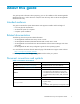
Figure 1 Fully Configured XP20000 Rack A basic XP20000 configuration consists of the following components: • • • • • One 19-inch, HP 10000 G2 42U rack model 10642 G2 (empty) One disk controller with control panel and SVP blade PC Channel adapters, disk adapters, cache and shared memory, one disk chassis (RO) Disks Power supplies, power distribution units (PDUs), backup batteries, power cords, and cabling Adding storage You can expand the disk array in the primary rack as follows: • Add one 60-disk chassis (
Dimensions and weights This table gives the dimensions and weights of the available racks. Use the packaged values when determining delivery space and loading requirements and use the unpackaged values during space and floor load planning. Rack specification Width with side panels Depth front to rear door Height 604.3 mm, 23.8 in. 1015 mm, 40 in. 2003.5 mm, 78.9 in.
Product Description AE190A HP XP20000 Rack Assembly #00x 4.5M power cord AE191A HP XP20000 DKC Disk Control Unit #001 kg lb 136 300 2.3 5.07 78.70 174 60Hz Power Option 2.0 4.41 #002 50Hz Power Option 1.5 3.31 AE132A HP XP24000/20000 SVP High Reliability Kit 4.17 9.19 AE135A HP XP24000/20000 8-port 4-Gbps FC CHA 2.80 6.17 AE136A HP XP24000/20000 16-Port 4-Gbps FC CHA 3.00 6.61 AE137A HP XP24000/20000 8-Port 4–Gbps FICON SW CHA 3.00 6.
Calculating the weight of your disk array configuration The total weight of your array configuration consists of the weight of the controller, the disk chassis, all the disk drives in each rack, and any optional components. Your site must have adequate floor strength to support the total weight of the array, from the delivery area to the computer room. You must calculate the total weight of your unpackaged array configuration. Use the provided worksheet and fill in the weights in your preferred units (kg or lb).
Weight calculation example worksheet Weight Quantity Total weight 300.0 1 300.0 5.07 1 5.1 174 1 173.5 60Hz Power Option 4.41 1 4.4 AE136A HP XP24000/20000 16 Port 4 Gb FC CHA 6.61 2 13.2 AE151A HP XP24000/20000 Cache Memory Adapter 4.85 1 4.9 AE152A HP XP24000/20000 8 GB Cache Memory 0.18 4 0.7 AE192A HP XP20000 Shared Memory Adapter 2.65 1 2.6 AE157A HP XP24000/20000 4 Gb Shared Memory 0.18 3 0.5 AE195A HP XP20000 DKA Disk Adapter Pair 5.73 1 5.
Make sure your computer room adheres to all national and local building codes for a data center/computer room environment. HP recommends that you follow these general guidelines: • Locate the computer room away from exterior walls of the building to avoid the heat gain from windows and exterior wall surfaces. • When exterior windows are unavoidable, use windows that are double or tripled glazed and shaded to prevent direct sunlight from entering the computer room.
or making structural changes to an existing site, consult your local building codes for fire prevention and protection guidelines. Equipment servicing hazards Your staff and HP service personnel require safe access to the disk array. Running electrical and data communication cables underneath your computer room’s raised floor is the best way to ensure that they do not create a safety hazard. Electrical hazards The disk array equipment racks contain dangerous voltages.
WARNING! If metal is used in the construction of the raised floor, ensure that there is a common ground connection between the raised floor and main floor to avoid possible build up of different voltage potentials. Failure to comply can result in serious injury to personnel and damage to equipment. Requirements for raised floors: • Raised floor access ramps must not exceed a 10 degree slope. • Use a raised floor system (254 to 305 mm, 10 to 12 in) for the most favorable room air distribution system.
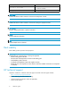
Equipment clearance and floor loading The following figure shows rack dimensions. Figure 2 Rack Assembly Footprint Calculating clearances The total floor clearance required for the disk array includes: • The actual space required by the equipment. • Service clearance — the floor space required to access the disk array. Never use this space for storage. The service clearance for the XP20000 rack is 30 inches in the rear and 48 inches in the front.
Temperature specifications Temperature range type Range Recommended operating temperature 21 to 24 degrees C 70 to 75 degrees F Specified operating temperature 16 to 32 degrees C 61 to 89 degrees F Nonoperating temperature –10 to +43 degrees C 14 to 109 degrees F Shipping and storage temperature (product packed in factory packing) –25 to +60 degrees C –13 to +140 degrees F Temperature shock immunity (maximum rate of temperature change) 10 degrees C per hour 18 degrees F per hour Humidity specificat
Condition Vibration Specification In operation 0.25 mm, 5–10 Hz 0.05 G, 10–300 Hz Not in operation 2.5 mm, 5–10 Hz 0.5 G, 10–70 Hz 0.05 mm, 70–99 Hz 1.0 G, 99–300 Hz Shipment and storage (product packed in factory packing) 0.5 G, 15 minutes (at four most severe resonances between 5–200 Hz) Shock specifications The following tables lists shock specifications.
Product No. Description Heat output (kW) Power consumption (kVA) AE191A HP XP20000 DKC Disk Control Unit 0.291 0.300 AE132A HP XP24000/20000 SVP High Reliability Kit 0.079 0.081 AE135A HP XP24000/20000 8 Port 4 Gb FC CHA 0.130 0.135 AE136A HP XP24000/20000 16 Port 4 Gb FC CHA 0.146 0.150 AE137A HP XP24000/20000 8 Port 4 Gb FICON SW CHA 0.146 0.150 AE138A HP XP24000/20000 8 Port 4 Gb FICON LW CHA 0.146 0.150 AE139A HP XP24000/20000 8 Port EXSA CHA 0.108 1.
Dust and pollution control Airborne contaminants and particles of a certain size and hardness can damage the disk array. Some of the most common contaminants are dust, smoke, ash, eraser debris, food crumbs, and salty air. Mechanical filters on the disk array protect it by trapping large dust particles. Smaller particles can pass through some filters and can eventually cause problems in mechanical parts.
system errors or a complete system shutdown. If required, an HP representative and your electrician can determine the current line voltage and make recommendations. SeeChapter 3 Electrical specifications for specific AC line voltage requirements. Avoid the use of a line voltage conditioner. Make sure that a power distribution unit (if used) provides the correct voltage to support your entire system.
When receptacles are used to connect disk array components to AC power, they must include a dedicated ground connection that is insulated from the receptacle. It is important that the receptacle box be grounded with an additional ground connection that is separate from the dedicated ground. The additional ground can be hard conduit. Specific AC power cords and plugs are available to suit the power requirements and receptacles in your location.
CAUTION: If you are planning or already have a site-wide UPS, HP recommends against using a product that is powered by a site-wide UPS for the HP XP20000. Make sure your UPS satisfies the power requirements listed under Heat dissipation and power consumption in this chapter and also under AC line voltage requirements in Chapter 3.
Site requirements
3 Electrical specifications The detailed electrical specifications in this chapter are provided to help your site electrician perform any necessary electrical work related to site prep. AC line voltage requirements The AC power requirements are essentially the same for both the primary and the second racks. Each rack operates on 200 VAC nominal, 20 amps, 50 or 60 Hz, single-phase power. An independent branch circuit and a circuit breaker are required for each AC input power cord.
Electrical specifications
CAUTION: The four PDU outputs shown in the figures are for internal power connections to the disk array only. Do not connect any other equipment to these outlets. Using the outlets for any equipment other than the disk array may compromise disk array reliability or availability. The second rack shown in the following figure has four connections to AC power. Its power requirements are 200 VAC, single phase, 20 Amps.
Connect each AC power cable to a separate receptacle on a separate circuit breaker, and connect each pair of power cords (the left pair and the right pair) to separate distribution panels to ensure power fault tolerance. CAUTION: Do not apply power until instructed to do so by HP. An HP representative should be present whenever the disk array is being connected to a new power source. Branch circuit requirements To protect the disk array, your building must be wired correctly.
CAUTION: Be sure to connect the power cords to the distribution panel as shown in the figure. Improper wiring of the neutral conductor may cause damage to the disk array. To reduce the risk of a wrong connection, use a plug and socket that are approved for this disk array. It is your electrician’s responsibility to select and install the proper plugs and receptacles. WARNING! High leakage current can occur between the power supply and the unit.
Electrical specifications
4 Delivery and unpacking The disk array equipment is shipped directly from HP. If the disk array is part of a system order, HP coordinates shipment from all HP locations so that all of the equipment arrives at your site at approximately the same time. When your equipment ships, HP provides you with carrier information and an expected delivery date. Factors beyond HP’s control can cause delivery delays.
Packaging configurations XP disk array cabinets are shipped in one of the following packaging configurations: • Full packaging — consists of a pallet, wooden loading ramp, inner packaging, and outer corrugated carton assembly. • Full packaging with wooden crate — consists of full packaging encased in a wooden crate. Unpacking process If you need to unpack the equipment without HP supervision, follow the instructions in this section. 1.
CAUTION: When disk array equipment is not located in a data center or computer room, it must be stored in a controlled area that meets environmental requirements (see “Environmental requirements”). Removing packaging materials See the figures below for key packaging points. • If shipped in a wooden crate: • Using an 11mm (7/16 in) ratchet or wrench, remove the six lag screws at the base of the crate.
Delivery and unpacking
Glossary ACP Array control processor. On some HP XP models, such as the HP XP12000, the ACP handles the passing of data between the cache and the physical drives. On other HP XP models, such as the HP XP20000, this function is handled by the disk adapter on the MIX board. AL Arbitrated loop. AL-PA Arbitrated loop physical address. allocation The ratio of allocated storage capacity versus total capacity as a percentage. “Allocated storage” refers to those LDEVs that have paths assigned to them.
control unit To organize the storage space attached to the DKC, you can group similarly configured logical devices (LDEVs) with unique control unit images (CUs). CUs are numbered sequentially. The disk array supports a certain number of CUs, depending on the disk array model. Each CU can manage multiple LDEVs. Therefore, to uniquely identify a particular LDEV requires both the CU number and the LDEV number. CU Control unit. CVS Custom volume size.
HA High availability. HBA Host bus adapter. A built-in function or a card installed in a PC or other host computer to enable connection of the host to the SAN. host mode Each port can be configured for a particular host type. These modes are represented as two-digit hexadecimal numbers. For example, host mode 08 represents an HP-UX host. hot standby Using two or more servers as a standby in case of a primary server failure. HP Hewlett-Packard Development Company.
PA Physical address. parity group A parity group is a disk configuration in which multiple disks work together to provide redundancy. Synonymous with “array group.” partition Dividing a specific physical disk into two or more areas as if there are two or more physical disks. path Paths are created by associating a port, a target, and a LUN ID with one or more LDEVs. PCI Power control interface or peripheral component interconnect.
SNMP Simple Network Management Protocol. SSID Storage subsystem identification. STC HP Storage Technology Center. SVP Service processor, which is the PC built into the disk controller. The SVP provides a direct interface into the disk array. SVP use is reserved for HP support representatives only. TB Terabyte. TCP/IP Transmission control protocol/Internet protocol TID Target ID. VSC Volume size customization. Synonymous with CVS. VOLID Volume ID. volume Synonymous with LDEV.
Glossary
Index A AC plugs, 35 power, 33 AC cabling European, 36 North American, 35 acoustics, 27 additional components, 17 air conditioning, 24 and metallic particulate contamination, 28 dust control, 28 air pressure, 21, 24, 28 airborne contaminants, 28 altitude, 24 antistatic carpeting, 23 containers, 21 floor wax, 21 flooring, 21 furniture, 21 area delivery, 20 audience, 7 B basic configuration, 15 branch circuit requirements, 36, 36 breakers, 29, 33 building codes, 21, 22, 29 C cables, 22, 35 as safety hazards
E earth ground, 29, 37 electrical requirements, 28 electrical specifications, 33 electromagnetic interference, 30 environmental requirements, 24 equipment servicing hazards, 22 ESD, 21, 25 European AC power cabling, 36 F fire safety, 21 floor clearances, 23 conductive, 21 covering, 23 cutouts, 22, 23 earth grounding, 21 grid panels, 23 grounding, 21, 23 tiles, and metallic particulate contamination, 28 waxed, 21 floor plan, 22 frequency, 29 furniture, conductive, 21 G grid panels, floor, 23 grounding, 29, 3
S safety, 21, 22 sales representative. See HP SR, 40 second rack, 15 service clearance, 22 servicing hazards, 22 shipping damage, 39 single phase cabling Europe, 36 North America, 35 site prep customer responsibilities, 11 objectives, 11 resources, 11 team, 11 site preparation checklist, 12 tasks, 11 time allowances, 14 sound pressure, 27 space planning, 22 specifications, 15 acoustic, 27 heat, 26 humidity, 25 power, 26 vibration, 25 SR.