HP StorageWorks XP Disk Array Mainframe Host Attachment and Operations Guide HP XP24000 Disk Array HP XP20000 Disk Array nl Abstract This guide provides requirements and procedures for connecting an XP disk array to a host system, and for configuring the disk array for use with the mainframe operating system. This document is intended for system administrators, HP representatives, and authorized service providers who are involved in installing, configuring, and operating the HP XP storage systems.
Legal and notice information © Copyright 2007-2010 Hewlett-Packard Development Company, L.P. Confidential computer software. Valid license from HP required for possession, use or copying. Consistent with FAR 12.211 and 12.212, Commercial Computer Software, Computer Software Documentation, and Technical Data for Commercial Items are licensed to the U.S. Government under vendor's standard commercial license. The information contained herein is subject to change without notice.
Contents 1 Overview of mainframe operations ....................................................... 7 Mainframe compatibility and functionality ...................................................................................... 7 Connectivity ............................................................................................................................... 8 Program products for mainframe ...................................................................................................
Hardware definition using IOCP (MVS, VM, or VSE) ............................................................... Hardware definition using HCD (MVS/ESA) .......................................................................... Defining the storage system to VM/ESA and z/VSE systems ..................................................... Defining the storage system to TPF ........................................................................................ Defining the storage system to mainframe Linux ...
Figures 1 Fiber connectors ..................................................................................................... 15 2 FICON protocol read/write sequence ........................................................................ 17 3 zHPF protocol read/write sequence .......................................................................... 17 4 Mainframe Logical Paths (Example 1) ........................................................................ 18 5 Mainframe logical paths (example 2) .
Tables 1 Mainframe operating system support ........................................................................... 7 2 XP Remote Web Console-based software for mainframe users ......................................... 9 3 Host/Server-Based Software for Mainframe Users ....................................................... 10 4 Comparing ESCON and FICON/zHPF physical specifications ...................................... 14 5 Comparing ESCON and FICON/zHPF logical specifications ........................
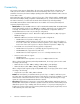
1 Overview of mainframe operations This chapter provides an overview of mainframe host attachment issues, functions, and operations.
Connectivity The storage system supports all-mainframe, all-open-system, and multi-platform configurations. The CHAs process the channel commands from the hosts and manage host access to cache. In the mainframe environment, the channel adapters (CHAs) perform CKD-to-FBA and FBA-to-CKD conversion for the data in cache.
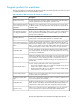
Program products for mainframe The following tables list and describe the XP Remote Web Console-based products and the host- and server-based products for use with mainframe systems. Table 2 XP Remote Web Console-based software for mainframe users Name Description XP Thin Provisioning Provides virtual storage capacity to simplify storage addition and administration, eliminate application service interruptions, and reduce costs.
Name Description Volume Retention Manager Allows users to protect data from I/O operations performed by hosts. Users can assign an access attribute to each logical volume to restrict read and/or write operations, preventing unauthorized access to data.
2 FICON/zHPF and ESCON host attachment This chapter describes and provides general instructions for attaching the storage system to a mainframe host using a FICON/zHPF or ESCON CHA. For details on FICON/zHPF connectivity, FICON/Open intermix configurations, and supported HBAs, switches, and directors, contact your HP representative.
For zSeries host attachment using ESCON, only the first 16 addresses of the LSSs can be used. The ranges of supported device addresses may be noncontiguous. Devices that are not mapped to a logical device respond and show address exceptions. When a primary controller connects to a secondary controller, the primary connection converts to a channel.
NOTE: For optimum performance, use a cable shorter than 103 km (64 mi). An ESCON host channel can connect to more than one storage unit port through an ESCON director. The S/390 or zSeries host system attaches to one port of an ESCON host adapter in the storage unit. Each storage unit adapter card has two ports. For the XP24000/XP20000 disk array, each ExSA has 4 ports per adapter card and 8 per pair.
are tag numbers. You need tag numbers for the path setup. To determine the tag number, use the devserv command with the rcd (read configuration data) parameter. Attaching FICON/zHPF CHAs You can attach the storage system to a host system using FICON adapters. The storage system can be configured with up to 112 FICON physical channel interfaces.
Item ESCON FICON/zHPF Multi Mode/ 62.5um Short wave 300m (1Gbps) / 150m (2Gbps) / 75m (4Gbps) 3 km Multi Mode/ 50um 500m (1Gbps) / 300m (2Gbps) / 150m (4Gbps) Connector Topologies ESCON connector LC-duplex (see Figure 1) Point-to-Point Point-to-Point Switched Point-to-Point Switched Point-to-Point Figure 1 Fiber connectors . FICON/zHPF logical specifications The following table compares the logical specifications of FICON/zHPF and ESCON.
FICON/zHPF operating environment The following table lists the operating environment required for FICON/zHPF. For more information about FICON/zHPF operating environments, including supported hosts and operating environments, see the IBM Redbooks. Table 6 Operating environment required for FICON/zHPF Items CPU Specification z9, z10 FICON Express FICON Express2 FICON Express4 z900 Native FICON FICON Express z990 FICON Express G5/G6 Native FICON z800, zSeries Operating system OS/390 Rev. 2.
Figure 2 FICON protocol read/write sequence . Figure 3 zHPF protocol read/write sequence . Hardware specifications For details on FICON/zHPF connectivity, FICON/Open intermix configurations, and supported HBAs, switches, and directors for the storage array, contact your HP representative. FICON CHAs The CHAs contain the microprocessors that process the channel commands from the host(s) and manage host access to cache.
Parameter 8MFS 8MFLR (DKA Slot Used) 8/ 16 / 24 / 32 / 40/ 48 / 56 / 64 / 72 / 80 / 88/ 96 / 104 / 112 / 16 / 24 / 32 / 40/ 48 / 56 / 64 / 72 / 80 / 88/ 96 / 104 / 112 Small Form Pluggable (SFP) Support Short Wave Long Wave Number of Ports per Storage System Maximum Cable Length 500m / 300m / 150m (See Note 2) 10km Note 1: The XP24000 supports up to six options while the XP20000 supports only one option.
Figure 5 Mainframe logical paths (example 2) . The FICON /zHPF CHAs provide logical path bindings that map user-defined FICON/zHPF logical paths. Specifically: • Each CU port can access 255 CU images (all CU images of logical storage system). • To the CU port, each logical host path (LPn) connected to the CU port is defined as a channel image number and a channel port address. The LPn identifies the logical host path by the channel image number and channel port address (excluding CU image number).
• Maximum number of CU images per storage system is 64. • Maximum number of logical paths per storage system is 131,072 (2048 X 48). Figure 7 FICON/zHPF channel adapter support for logical paths (example 2) . Supported topologies FICON and FICON/zHPF support the same topologies.
Sharing a control unit through a Fibre Channel switch allows communication between a number of channels and the control unit to occur either: • Over one switch-to-CU link, such as when a control unit has only one link to the Fibre Channel switch, or • Over multiple-link interfaces, such as when a control unit has more than one link to the Fibre Channel switch. In a FICON switched point-to-point topology, one Fibre Channel link is attached to the FICON channel.
Figure 10 Example of a cascaded FICON topology . In a cascaded FICON topology, one or two switches reside at the topmost (root) level, between the channel (CHL) and disk controller (DKC) ports (see Figure 11. With this configuration, multiple channel images and multiple control unit images can share the resources of the Fibre Channel link and Fibre Channel switches, so that multiplexed I/O operations can be performed.
Figure 11 Example of ports in a cascaded FICON topology . Required high-integrity features FICON directors in a cascaded configuration (see Figure 12) require switches that support the following high-integrity features: • Fabric binding: This feature lets an administrator control the switch composition of a fabric by registering WWNs in a membership list and explicitly defining which switches are capable of forming a fabric. In this way, an operator can deny non-authorized switches access into a fabric.
Viewing path information Depending on the microcode version installed on the storage system, the Link values displayed on the service processor (SVP) Logical Path Status screen may appear as 3-byte values for cascaded topologies: • The first byte corresponds to the switch address. • The second byte corresponds to the port address. • The third byte corresponds to the FC-AL port (this is a constant value in FICON).
Table 8 FICON host and RAID physical connection specifications XP disk array Host z900 z990 z9, z10 G5/G6 Native FICON FICON Express FICON Express FICON Express2 FICON Express4 Native FICON 1 Gbps 1 / 2 Gbps 4 Gbps 1 Gbps Link Bandwidth 1 / 2 / 4 Gbps Connector LC-Duplex SC-Duplex LC-Duplex LC-Duplex SC-Duplex Single Mode Single Mode Single Mode Single Mode Single Mode Multi Mode Multi Mode Multi Mode Multi Mode Multi Mode Cable (Auto-negotiation) Logical host connection spe
In Figure 16, up to 16,384 unit addresses are supported for each CHL port (in this case, the maximum limit is increased). In this example, CHL path configuration can be reduced. Figure 16 Logical host connections (example 2 - FICON/zHPF) . Enabling XPfor Compatible High Perf FICON connectivity software (zHPF) operations Activating the zHPF program product The zHPF PP license is required to activate zHPF on the storage system.
Installing zHPF in a switch cascading configuration In the storage system, when the zHPF PP is installed, the zHPF feature is enabled per channel path. For point-to-point (direct) connection and single-switch connection, zHPF is dynamically enabled per channel path. However, in cascading-switch connections, it is not automatically enabled (if you perform option (1) or (2) from “Enabling the zHPF function” on page 26 to enable zHPF, zHPF IO would not be issued).
FICON/zHPF and ESCON host attachment
3 Mainframe operations This chapter discusses the operations available for mainframe hosts. Mainframe configuration The first step in configuring the storage system is to define the storage system to the mainframe host(s).
Mainframe hardware definition Hardware definition using IOCP (MVS, VM, or VSE) The I/O Configuration Program (IOCP) can be used to define the storage system in MVS, VM, and VSE environments (wherever HCD cannot be used). The storage system supports up to 255 control unit (CU) images and up to 65,280 LDEVs. Each CU image can hold up to 256 LDEV addresses. A CU image is the same as an IBM logical sub-system (LSS).
UNIT=2105,CUADD=04,UNITADD=((00,256)) CNTLUNIT CUNUMBR=8600,PATH=(F9,FB,FD,FF), LINK=(04,**,**,05), UNIT=2105,CUADD=05,UNITADD=((00,256)) * * IODEVICE ADDRESS=(8100,064),CUNUMBR=(8100),STADET=Y,UNIT=3390B IODEVICE ADDRESS=(8180,128),CUNUMBR=(8100),STADET=Y,UNIT=3390A* ,UNITADD=80 IODEVICE ADDRESS=(8200,064),CUNUMBR=(8200),STADET=Y,UNIT=3390B IODEVICE ADDRESS=(8280,128),CUNUMBR=(8200),STADET=Y,UNIT=3390A* ,UNITADD=80 IODEVICE ADDRESS=(8300,064),CUNUMBR=(8300),STADET=Y,UNIT=3390B IODEVICE ADDRESS=(8380,128)
• To protect data integrity due to multiple operating systems sharing these volumes, these devices require FEATURE=SHARED. NOTE: If you maintain separate IOCP definitions files and create your SCDS or IOCDS manually by running the IZP IOCP or ICP IOCP program, you must define each CU image on a storage system using one CNTLUNIT statement in IOCP.
Parameter Value Number of devices 64 Device type 3390 Connected to CUs Specify the control unit number(s). Table 11 HCD definition for 256 LVIs Parameter Value Control Frame: Control unit number Specify the control unit number. Control unit type NOCHECK* Use UIM 3990 for more than 128 logical paths. Use UIM 3990-6 for 128 or fewer logical paths.
1. From an ISPF/PDF primary options menu, select the HCD option to display the basic HCD panel. On this panel you must verify the name of the IODF or IODF.WORK I/O definition file to be used. San Diego OS/390 R2.8 Master MENU OPTION ===> HC SCROLL ===> PAGE USERID - HDS TIME - 20:23 IS P IP R SD HC BMB BMR BMI SM IC OS OU S X ISMF PDF IPCS RACF SDSF HCD BMR BLD BMR READ BMR INDX SMP/E ICSF SUPPORT USER SORT EXIT F1=HELP F7=UP 2.
3. On the Define, Modify, or View Configuration Data panel, select option 4 to display the Control Unit List panel. OS/390 Release 5 HCD .------------- Define, Modify, or View Configuration Data --------------. _ | | | Select type of objects to define, modify, or view data. | | | | 4_ 1. Operating system configurations | | consoles | | system-defined generics | | EDTs | | esoterics | | user-modified generics | | 2. Switches | | ports | | switch configurations | | port matrix | | 3.
5. On the Add Control Unit panel, input the following new information, or edit the information if pre-loaded from an “Add like” operation, and then press Enter: • Control unit number • Control unit type: 2105 • Switch information only if a switch exists. Otherwise leave switch and ports blank. .-------------------------- Add Control Unit ---------------------------. | | | | | Specify or revise the following values. | | | | Control unit number . . . . 8000 + | | | | Control unit type . . . . .
7. On the Add Control Unit panel, enter CHPIDs that attach to the control unit, the control unit address, the device starting address, and the number of devices supported, and then press Enter. Goto Filter Backup Query Help .--------------------------- Add Control Unit ----------------------------. | | | | | Specify or revise the following values. | | | | Control unit number . : 8000 Type . . . . . . : 2105 | | Processor ID . . . . . : PROD | | | | Channel path IDs . . . .
9. On the Control Unit List panel, add devices to the new Control Unit, input an S next to CU 8000, and then press Enter. Goto Filter Backup Query Help -------------------------------------------------------------------------Control Unit List Row 40 of 41 Command ===> ___________________________________________ Scroll ===> PAGE Select one or more control units, then press Enter.
11. On the Add Device panel, enter the following, and then press Enter: • Device number • Number of devices • Device type: 3390, 3390B for PAV base device, or 3390A for PAV alias device Goto Filter Backup Query Help .-------------------------------- Add Device ---------------------------------. | | | | | Specify or revise the following values. | | | | Device number . . . . . . . . 8000 (0000 - FFFF) | | Number of devices . . . . . . 128 | | Device type . . . . . . . . .
13. On the Define Device / Processor panel, enter the values shown in the following screen, and press Enter. .------------------------- Define Device / Processor -------------------------. | | | | | Specify or revise the following values. | | | | Device number . : 8000 Number of devices . . . . : 128 | | Device type . . : 3390B | | Processor ID . . : PROD | | | | Unit address . . . . . . . . . . 00 + (Only necessary when different from | | the last 2 digits of device number) | | Time-Out . . . . . . . . . .
15. On the Define Device to Operating System Configuration panel, input an S next to the Config ID, and then press Enter. .----------- Define Device to Operating System Configuration -----------. | Row 1 of 1 | | Command ===> _____________________________________ Scroll ===> PAGE | | | | Select OSs to connect or disconnect devices, then press Enter. | | | | Device number . : 8100 Number of devices : 128 | | Device type . . : 3390B | | | | / Config.
18. The Update Serial Number, Description and VOLSER panel now displays the device addresses. To add more control units or device addresses, repeat the previous steps. .---------- Update Serial Number, Description and VOLSER -----------. | Row 1 of 128 | | Command ===> _________________________________ Scroll ===> PAGE | | | | Device number . . : 8000 Number of devices : 128 | | Device type . . . : 3390B | | | | Specify or revise serial number, description and VOLSER.
For information on supported versions, Linux kernel levels, and other details, contact your HP representative. For information on preparing the storage system for Linux host attachment, see the IBM publication. Mainframe operations Initializing the LVIs The storage system LVIs require only minimal initialization before being brought online. The following shows an MVS ICKDSF JCL example of a minimal init job to write a VOLID and VTOC. NOTE: PAV base and alias devices require additional definition.
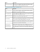
Command Argument Storage System NOPRESERVE, NOSKIP, RAMAC CC = 0, ALT information not displayed. NOCHECK XP disk array CC = 0 ALLTRACKS, ASSIGN, RECLAIM RAMAC CC = 12 Invalid parameter(s) for device type. XP disk array INSTALL SETMODE (3390) SETMODE (3380) ANALYZE BUILDX REVAL REFRESH DATA, NODATA CONTROL INIT REFORMAT 44 Return Code Mainframe operations In case of PRESERVE: CC = 12 In case of NO PRESERVE: CC = 0. RAMAC CC = 0 (but not recommended by IBM).
Command CPVOLUME Argument Storage System Return Code RAMAC CC = 0, Readcheck parameter not allowed. XP disk array CC=0 z/OS (MVS) Cache operations To display the cache statistics under MVS DFSMS, use the operator command: D SMS, CACHE. The following example shows the cache statistics reported by the storage system. The storage system reports cache statistics for each SSID in the storage system.
NOTE: In normal cache replacement, bypass cache, or inhibit cache loading mode, the storage system performs a special function to determine whether the data access pattern from the host is sequential. If the access pattern is sequential, the storage system transfers contiguous tracks from the disks to cache ahead of time to improve cache hit rate.
• DESTAGE SUBSYSTEM zVSE (VSE/ESA) Cache operations When using VSE/ESA to manage the storage system, the following CACHE commands are effective across multiple SSIDs: • • • • CACHE SUBSYS=cuu,ON|OFF|STATUS CACHE SUBSYS=cuu,FAST,ON|OFF CACHE SUBSYS=cuu,NVS,ON|OFF CACHE SUBSYS=cuu,REINIT NOTE: SIMs indicating a drive failure may not be reported to the VSE/ESA console. Because the RAID technology and dynamic spare drives ensure non-stop processing, a drive failure may not be noticed by the console operator.
Mainframe operations
4 Linux operations This chapter describes storage system operations in a Linux host environment. Overview of zLinux operations The storage system supports attachment to the following mainframe Linux operating systems: • Red Hat Linux for S/390 and zSeries • SuSE Linux Enterprise Server for IBM zSeries For information on supported versions, Linux kernel levels, and other details, contact your HP representative.
NOTE: zSeries FCP host system running SuSE SLES 9 or Red Hat Enterprise Linux 3.0 can only be attached through a switched-fabric configuration. Hosts cannot be attached using a direct configuration. Attaching FCP adapters to zSeries hosts running Linux Linux solutions are available for the 31- and 64-bit environments. The availability of this option depends on the zSeries model and the Linux distribution. Fibre Channel support is available for both direct and switched attachment.
Setting up storage units for zSeries hosts running Linux You must begin by first collecting the following software configuration information to prepare a Linux system for accessing the storage unit through a Fibre Channel: • Host name of the server hosting the Linux system. • Device address and CHPID of the FCP port that is attached to the Linux machine. FICON/zHPF requires a CHPID type FC.
• FCP port on the storage unit: Enclosure 3 Slot 1 • WWPN of the FCP port on the storage unit: 50:05:07:63:00:c8:95:89 Setting up a Linux system to use FCP protocol devices on zSeries hosts Begin by collecting the following software configuration information to prepare a Linux system to access the storage unit through a Fibre Channel: • • • • • Host name of the server hosting the Linux system Device address (and CHPID) of the FCP port that is attached to the Linux machine WWPN of the FCP port on the zSeri
“Setting up storage units for zSeries hosts running Linux” on page 51 provides an example of the prerequisite information that must be obtained to run FCP Linux on the zSeries. 1. 2. 3. Choose one of the following methods to add devices: write a script or manually add the device. • To add more than one device to your SCSI configuration, write a small script that includes all the parameters included. This is an optional step.
Figure 17 Basic ESCON Configuration . The channels are grouped into a channel-path group for multi-pathing capability to the storage unit ESCON adapters. ESCON to FICON migration example for a zSeries or S/390 host The following figure shows another example of a S/390 or zSeries host system with four ESCON channels. In this example, two FICON channels are added to an S/390 or zSeries host.
Figure 18 Four channel ESCON system with two FICON channels added . This figure shows four ESCON adapters and two ESCON directors. The illustration also shows the channel path group and FICON directors through which the two FICON adapters are installed in the storage unit. The two FICON directors are not required. You can improve reliability by eliminating a single point of failure. The single point of failure might be present if both FICON channels are connected to a single FICON director.
FICON configuration example for a zSeries or S/390 host The following figure provides a FICON configuration example for a zSeries or S/390 host that illustrates how to remove the ESCON paths. The S/390 or zSeries host has four ESCON channels connected to two ESCON directors. The S/390 or zSeries host system also has two FICON channels. Figure 19 Non-Disruptive ESCON Channel Removal . You can remove the ESCON adapters non-disruptively from the storage unit while I/O continues on the FICON paths.
Migrating from a FICON bridge to a native FICON attachment FICON bridge overview The FICON bridge is a feature card of the ESCON Director 9032 Model 5. The FICON bridge supports an external FICON attachment and connects internally to a maximum of eight ESCON links. The volume on these ESCON links is multiplexed on the FICON link. You can perform the conversion between ESCON and FICON on the FICON bridge. FICON bridge configuration The following figure shows an example of a FICON bridge.
Figure 21 FICON mixed channel configuration . In the example, one FICON bridge was removed from the configuration. The FICON channel that was connected to that bridge is reconnected to the new FICON director using the storage unit FICON adapter. The channel-path group was changed to include the new FICON path. The channel-path group is now a mixed ESCON and FICON path group. I/O operations continue to the storage unit across this mixed path group.
Figure 22 Native FICON Configuration . RSCNs on zSeries hosts McDATA and CNT switches ship without any configured zoning. This unzoned configuration enables the default zone on some McDATA switches. This configuration enables all ports in the switch with a FC connection to communicate with each other and to receive registered state change notifications about each other. You can set the zones. Here are some recommendations: • If you have FICON-only environments, do not disable the default zone.
Linux operations
5 Troubleshooting This chapter provides error codes, troubleshooting guidelines and customer support contact information. Troubleshooting For troubleshooting information on the storage system, see the HP StorageWorks XP24000/XP20000 Disk Array Owner Guide. For troubleshooting information on XP Remote Web Console, see the HP StorageWorks XP24000/XP20000 Remote Web Console User Guide.
Troubleshooting
6 Support and Other Resources Contacting HP For worldwide technical support information, see the HP support website: http://www.hp.
• • • • http://www.hp.com/go/storage http://www.hp.com/support/manuals http://www.hp.com/storage/spock http://www.hp.
Glossary AL-PA Arbitrated loop physical address. CHA Channel Adapters. CHPID Channel path ID. command device A volume on the disk array that accepts HP StorageWorks Continuous Access or HP StorageWorks Business Copy control operations which are then executed by the array. CU Control Unit. Contains LDEVs and is approximately equivalent to SCSI Target ID. CVS Custom volume size.
FICON Fibre connectivity. Hardware that connects the mainframe to the control unit. HBA Host bus adapter. HCD Hardware Configuration Definition. HMC Hardware management console. host mode Each port can be configured for a particular host type. These modes are represented as two-digit hexadecimal numbers. For example, host mode 08 represents an HP-UX host. IOCP Input/output configuration program. LD, LDEV Logical device.
R-SIM Remote service information message. SAN Storage area network. A network of storage devices available to one or more servers. SIM Service information message. SNMP Simple Network Management Protocol. A widely used network monitoring and control protocol. Data is passed from SNMP agents, which are hardware and/or software processes reporting activity in each network device (hub, router, bridge, and so on) to the workstation console used to oversee the network.
Glossary
Index F A algorithms dynamic cache mgmt, 45 alias address range, 33 G C glossary, 65 cache loading mode, 46 statistics, 45 CNTLUNIT statement, 32 commands cache, 47 idcams setcache, 46 listdata, 45 listdata status, 46 contacting HP, 63 conventions storage capacity values, 64 conversion fba to ckd, 8 copy functions dasd on RAID, 10 D data sequential access pattern , 46 data integrity feature=shared, 31 data transfer max speed, 8 document related documentation, 63 documentation HP website, 63 providing
storage capacity values conventions, 64 Subscriber's Choice, HP, 63 switch information, 36 system vm/esa, 42 T technical support, 63 HP, 63 time interval mih max, 29 track transfer counters report, 46 U utilities hcd for lvi, 32 ickdsf, 43 V volume logical caching status, 45 W websites HP, 63 HP Subscriber's Choice for Business, 63 product manuals, 63 70