
HP StorageWorks XP Disk Array Mainframe Host Attachment and Operations Guide XP24000, XP20000 (A5951 - 96151, September 2007)
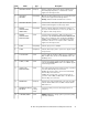


DescriptionTypeNameItem
When lit, indicates that low DC voltage, high DC current,
abnormally high temperature, or a failure has occurred.
Applies to both storage clusters.
LED (Red)SUBSYSTEM ALARM2
On: Indicates that a SIM (Message) was generated from either
of the clusters. Applied to both storage clusters.
LED (Amber)SUBSYSTEM
MESSAGE
3
Blinking: Indicates that the SVP failure has occurred.
Used to un-fence a fenced drive path and to release the Write
Inhibit command. Applies to both storage clusters.
SwitchSUBSYSTEM RESTART4
When lit, indicates that remote maintenance activity is in
process. If remote maintenance is not in use, this LED is not
lit. Applies to both storage clusters.
LED (Amber)REMOTE
MAINTENANCE
PROCESSING
5
Used for remote maintenance. While executing remote
maintenance (the REMOTE MAINTENANCE PROCESSING
SwitchREMOTE
MAINTENANCE
ENABLE/DISABLE
6
LED in item 5 is blinking), when switching from ENABLE to
DISABLE, remote maintenance is interrupted. If the remote
maintenance function is not used, this switch is ineffective.
Applies to both storage clusters.
Indicates input power is available.LED (Amber)BS-ON7
Indicates that storage system is powered on. Applies to both
storage clusters.
LED (Green)PS-ON8
Used to enable the PS ON/ PS OFF switch. To enable the PS
ON/ PS OFF switch, turn the PS SW ENABLE switch to the
ENABLE position.
SwitchPS SW ENABLE9
Used to power storage system on/off. This switch is valid
when the PS REMOTE/LOCAL switch is set to LOCAL. Applies
to both storage clusters.
SwitchPS ON / PS OFF10
This switch specifies the storage system powering on operation
to be done after the AC power is turned on.
SwitchAUTO PS-ON
ENABLE/DISABLE
11
ENABLE: The storage system is powered on automatically
after the AC power is turned on.
DISABLE: The storage system is powered on through on
operation of the PS ON/ PS OFF switch or the PCI control
after the AC power is turned on.
This LED shows status of EPO switch on the rear door. OFF:
Indicates that the EPO switch is off. ON: Indicates that the
EPO switch is on.
LED (Red)EMERGENCY12
Used to shut down power to both storage clusters in an
emergency.
1-Way
Locking
Switch
EMERGENCY POWER
OFF (EPO)
13
REMOTE position: The storage system is powered on/off by
instructions from CPU.
SwitchPS REMOTE/LOCAL14
XP Disk Array Mainframe Host Attachment and Operations Guide 61