
HP StorageWorks XP Disk Array Mainframe Host Attachment and Operations Guide XP24000, XP20000 (A5951 - 96151, September 2007)

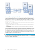
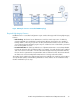
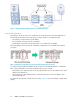
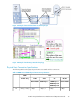

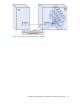


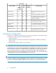

Figure 11 Required High-Integrity Features for Cascaded Topologies
Viewing Path Information
Depending on the microcode version installed on the storage system, the Link values displayed on
the SVP Logical Path Status screen may appear as 3-byte values for cascaded topologies:
• The first byte corresponds to the switch address.
• The second byte corresponds to the port address.
• The third byte corresponds to the FC-AL port (this is a constant value in FICON).
The following figure shows how the link information is displayed in non-cascaded and cascaded
topologies.
Figure 12 Example of Link Values for Non-Cascaded and Cascaded Topologies
To confirm the logical path of a FICON cascade connection in the SVP Maintenance − Mainframe
Path − Physical Path Status screen and Logical Path Status screen, note that:
• The first byte in the 3-byte Link value on the Logical Path Status screen is the address of the switch
address at the channel site.
• The first byte in the 3-byte LINK Self value on Physical Path Status screen is the address of the
switch at the DKC site.
To confirm the cascade path, compare these two values. Figure 14 shows an example of a path status
display.
FICON and ESCON Host Attachment34