
HP StorageWorks XP Disk Array Mainframe Host Attachment and Operations Guide XP24000, XP20000 (A5951 - 96151, September 2007)

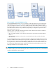
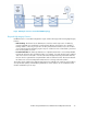
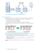

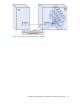


Figure 9 Example of a Cascaded FICON Topology
In a Cascaded FICON topology, one or two switches reside at the topmost (root) level, between the
CHL and DKC ports (see Figure 10. With this configuration, multiple channel images and multiple
control unit images can share the resources of the Fibre Channel link and Fibre Channel switches, so
that multiplexed I/O operations can be performed. Channels and control unit links can be attached
to the Fibre Channel switches in any combination, depending on configuration requirements and
Fibre Channel switch resources.
Sharing a control unit through a Fibre Channel switch allows communication between a number of
channels and the control unit to occur either:
• Over one switch-to-CU link, such as when a control unit has only one link to the Fibre Channel
switch, or
• Over multiple-link interfaces, such as when a control unit has more than one link to the Fibre
Channel switch.
In a Cascaded FICON topology, one Fibre Channel link is attached to the FICON channel. From the
switch, the FICON channel communicates with a number of FICON CUs on different switch ports. At
the control unit, the control unit and device-addressing capability is the same as the point-to-point
topology. However, communication and addressing capabilities are increased for the channel when
it is connected to a Fibre Channel switch, and can use the domain and port address portion of the
24-bit N_Port address to access multiple control units.
NOTE:
The domain address portion of the FC 24-bit port address is different because there are two Fibre Channel
switches in the channel-to-control unit path.
FICON and ESCON Host Attachment32