HP StorageWorks XP Disk Array Configuration Guide HP HP HP HP HP XP24000 Disk Array XP20000 Disk Array XP12000 Disk Array XP10000 Disk Array 200 Storage Virtualization System Abstract This guide provides requirements and procedures for connecting an XP disk array or SVS 200 to a host system, and for configuring the disk array for use with a specific operating system.
© Copyright 2003, 2011 Hewlett-Packard Development Company, L.P. Confidential computer software. Valid license from HP required for possession, use or copying. Consistent with FAR 12.211 and 12.212, Commercial Computer Software, Computer Software Documentation, and Technical Data for Commercial Items are licensed to the U.S. Government under vendor's standard commercial license. The information contained herein is subject to change without notice.
Contents 1 Overview................................................................................................10 What's in this guide................................................................................................................10 Audience...............................................................................................................................10 Features and requirements................................................................................................
Verifying the host recognizes array devices............................................................................36 Configuring disk devices..........................................................................................................36 Writing signatures..............................................................................................................36 Creating and formatting disk partitions.................................................................................
Setting the host mode for the disk array ports........................................................................59 Setting the UUID................................................................................................................60 Setting the system option modes..........................................................................................62 Configuring the Fibre Channel ports.....................................................................................
Creating the file systems.....................................................................................................84 Creating file systems with ext2........................................................................................85 Creating the mount directories.............................................................................................85 Creating the mount table....................................................................................................
Mounting and verifying the file systems...............................................................................113 11 Citrix XenServer Enterprise......................................................................115 Installation roadmap.............................................................................................................115 Installing and configuring the disk array..................................................................................115 Defining the paths.......
NonStop.............................................................................................................................146 Supported emulations.......................................................................................................146 Emulation specifications....................................................................................................146 OpenVMS..................................................................................................................
Contents Contents 9
1 Overview What's in this guide This guide includes information on installing and configuring P9000 disk arrays. The following operating systems are covered: • HP-UX • Windows • Novell Netware • NonStop • OpenVMS • VMware • Linux • Solaris • IBM AIX For additional information on connecting disk arrays to a host system and configuring for a mainframe, see the HP StorageWorks P9000 Mainframe Host Attachment and Operations Guide.
For all operating systems, before installing the disk array, ensure the environment conforms to the following requirements: • Fibre Channel Adapters (FCAs): Install FCAs, all utilities, and drivers. For installation details, see the adapter documentation. • HP StorageWorks XP Remote Web Console or HP StorageWorks P9000 or XP Command View Advanced Edition Software for configuring disk array ports and paths. • HP StorageWorks XP Array Manager.
Device emulation types The XP family of disk arrays and the SVS 200 support these device emulation types: • OPEN-x devices: OPEN-x logical units represent disk devices. Except for OPEN-V, these devices are based on fixed sizes. OPEN-V is a user-defined size based on a CVS device. Supported emulations include OPEN-3, OPEN-8, OPEN-9, OPEN-E, OPEN-L, and OPEN-V devices.
Your HP representative might need to set specific disk array system modes for these products. Check with your HP representative for the current versions supported. • For I/O path failover, different products are available from Oracle, Veritas, and HP. Oracle supplies software called STMS for Solaris 8/9 and Storage Multipathing for Solaris 10. Veritas offers VxVM, which includes DMP. HP supplies HDLM.
2 HP-UX You and the HP service representative each play a role in installation. The HP service representative is responsible for installing the disk array and formatting the disk devices. You are responsible for configuring the host server for the new devices with assistance from the HP service representative. Installation roadmap Perform these actions to install and configure the disk array: 1. 2. 3. 4.
Defining the paths Use P9000 or XP Command View Advanced Edition Software or XP Remote Web Console (shown) to define paths between hosts and volumes (LUNs) in the disk array. This process is also called “LUN mapping.
CAUTION: The correct host mode must be set for all new installations (newly connected ports) to HP-UX hosts. Do not select a mode other than 08 for HP-UX. Changing a host mode after the host has been connected is disruptive and requires the server to be rebooted. When a new host group is added, additional host group modes (options) can be configured. The storage administrator must verify if an additional host group mode is required for the host group.
Configuring the Fibre Channel ports Configure the disk array Fibre Channel ports by using P9000 or XP Command View Advanced Edition Software or XP Remote Web Console (shown). Select the settings for each port based on your SAN topology. Use switch zoning if you connect different types of hosts to the array through the same switch. Installing and configuring the host This section explains how to install and configure Fibre Channel adapters (FCAs) that connect the host to the disk array.
Figure 2 Multi-cluster environment (HP-UX) Within the SAN, the clusters can be homogeneous (all the same operating system) or heterogeneous (mixed operating systems). How you configure LUN security and fabric zoning depends on the operating system mix and the SAN configuration.
Use the ioscan –f command, and verify that the rows shown in the example are displayed. If these rows are not displayed, check the host adapter installation (hardware and driver installation) or the host configuration. Example # ioscan Class ... fc lan fcp ext bus –f I H/W Path Driver S/W State H/W Type Description 0 1 0 2 fcT1 fcT1_cntl fcp fcpdev CLAIMED CLAIMED CLAIMED CLAIMED HP Fibre ... HP Fibre ... FCP Proto... FCP Devic... 8/12 8/12.5 8/12.8 8/12.8.0.255.
• z = LUN • c stands for controller • t stands for target ID • d stands for device The numbers x, y, and z are hexadecimal. Table 3 Device file name example (HP-UX) 5. SCSI bus instance number Hardware path SCSI TID LUN File name 00 14/12.6.0 6 0 c6t0d0 00 14/12.6.1 6 2 c6t0d1 Verify that the SCSI TIDs correspond to the assigned port address for all connected ports (see mapping tables in SCSI TID map for Fibre Channel adapters (HP-UX), for values).
Verifying the device files and drivers The device files for new devices are usually created automatically during HP-UX startup. Each device must have a block-type device file in the /dev/dsk directory and a character-type device file in the /dev/rdsk directory. However, some HP-compatible systems do not create the device files automatically. If verification shows that the device files were not created, follow the instructions in “Creating the device files” (page 21).
repeat the procedures in “Verifying device recognition” (page 19) to verify new device recognition and the device files and driver. Example # insf -e insf: Installing special files for mux2 instance 0 address 8/0/0 : : : : : : : : # Failure of the insf –e command indicates a SAN problem. If the device files for the new disk array devices cannot be created automatically, you must create the device files manually using the mknodcommand as follows: 1. 2. Retrieve the device information you recorded earlier.
6. Create the device files for all disk array devices (SCSI disk and multiplatform devices) using the mknodcommand. Create the block-type device files in the /dev/dsk directory and the character-type device files in the /dev/rdsk directory. Example # cd /dev/dsk Go to /dev/dsk directory. # mknod /dev/dsk/c2t6d0 b 31 0x026000 Create block-type file. File name, b=block-type, 31=major #, 0x026000= minor # # cd /dev/rdsk Go to /dev/rdsk directory.
The physical volumes that make up one volume group can be located either in the same disk array or in other disk arrays. To allow more volume groups to be created, use SAM to modify the HP-UX system kernel configuration. See Reference information for the HP System Administrator Manager SAM for details. The newer releases of HP-UX have deprecated the SAM tool and replaced it with the System Management Homepage (SMH) tool. To create volume groups: 1. 2. 3.
9. Use vgdisplay –v to verify that the volume group was created correctly. The –v option displays the detailed volume group information.
To create logical volumes: 1. Use the lvcreate –L command to create a logical volume. Specify the volume size (in megabytes) and the volume group for the new logical volume. HP-UX assigns the logical volume numbers automatically (lvol1, lvol2, lvol3).
Creating the file systems Create the file system for each new logical volume on the disk array. The default file system types are: • HP-UX OS version 10.20 = hfs or vxfs, depending on entry in the /etc/defaults/fs file. • HP-UX OS version 11.0 = vxfs • HP-UX OS version 11.i = vxfs To create file systems: 1. Use the newfs command to create the file system using the logical volume as the argument.
Example # pvchange -t 60 /dev/dsk/c0t6d0 Physical volume "/dev/dsk/c0t6d0" has been successfully changed. Volume Group configuration for /dev/vg06 has been saved in /etc/lvmconf/vg06.conf. 3. Verify that the new I/O timeout value is 60 seconds using the pvdisplay command: Example # pvdisplay /dev/dsk/c0t6d0 --- Physical volumes --PV Name /dev/dsk/c0t6d0 VG Name /dev/vg06 PV Status available : Stale PE 0 IO Timeout (Seconds) 60 [New I/O timeout value] 4.
/ldev/vg00/lvol1 : /ldev/vg06/lvol1 4. 59797 59364 0 100% / 2348177 9 2113350 0% /AHPMD-LU00 As a final verification, perform some basic UNIX operations (for example file creation, copying, and deletion) on each logical device to make sure that the devices on the disk array are fully operational. Example #cd /AHPMD-LU00 #cp /bin/vi /AHPMD-LU00/vi.back1 #ls -l drwxr-xr-t 2 root root 8192 Mar 15 11:35 lost+found -rwxr-xr-x 1 root sys 217088 Mar 15 11:41 vi.back1 #cp vi.back1 vi.
3. 30 HP-UX Use the bdf command to verify the file system again.
3 Windows You and the HP service representative each play a role in installation. The HP service representative is responsible for installing the disk array and formatting the disk devices. You are responsible for configuring the host server for the new devices with assistance from the HP service representative. Installation roadmap Perform these actions to install and configure the disk array: 1. 2. 3.
In P9000 or XP Command View Advanced Edition Software, LUN mapping includes: • Configuring ports • Creating storage groups • Mapping volumes and WWN/host access permissions to the storage groups For more information about LUN mapping, see the HP StorageWorks XP LUN Manager User’s Guide, HP StorageWorks XP LUN Configuration and Security Manager user guide: HP XP12000 Disk Array, HP XP10000 Disk Array, HP 200 Storage Virtualization System, or Remote Web Console online help.
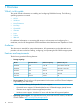
The available host mode settings are as follows: Table 6 Host mode settings (Windows) Host mode Description 2C (available on some array models) HP recommended. For use with LUSE volumes when online LUN expansion is required or might be required in the future. 0C HP recommended. Use if future online LUN expansion is not required or planned.
Table 8 Host group modes (options) Windows Host Group Mode 6 Function Default Parameter Setting Failure for TPRLO Inactive When using the Emulex FCA in the Windows environment, the parameter setting for TPRLO failed. After receiving TPRLO and FCP_CMD, respectively. PRLO will respond when HostMode=0x0C/ 0x2C and HostModeOption=0x06. (MAIN Ver.50-03-14-00/00 and later) 13 SIM report at link failure.
Installing and configuring the host This section explains how to install and configure Fibre Channel adapters (FCAs) that connect the host to the disk array. Loading the operating system and software Follow the manufacturer's instructions to load the operating system and software onto the host. Load all OS patches and configuration utilities supported by HP and the FCA manufacturer.
Figure 3 Multi-cluster environment (Windows) Connecting the disk array The HP service representative performs the following steps to connect the disk array to the host: 1. 2. 3. Verifying operational status of the disk array channel adapters, LDEVs, and paths. Connecting the Fibre Channel cables between the disk array and the fabric switch or host. Verifying the ready status of the disk array and peripherals. Verifying the host recognizes array devices 1. 2. 3. 4. 5. 6. 7.
3. 4. 5. Click OK to update the system configuration and start the Write Signature wizard. For each new disk, click OK to write a signature, or click No to prevent writing a signature. When you have performed this process for all new disks, the Disk Management main window opens and displays the added disks. Creating and formatting disk partitions Dynamic Disk is supported with no restrictions for a disk array connected to a Windows 2000/2003/2008 system. For more information, see Microsoft's online help.
3. 38 Windows Copy a file from an existing drive to each new drive to verify the new drives are working, and then delete the copies.
4 Novell NetWare You and the HP service representative each play a role in installation. The HP service representative is responsible for installing the disk array and formatting the disk devices. You are responsible for configuring the host server for the new devices with assistance from the HP service representative. Installation roadmap Perform these actions to install and configure the disk array: 1. 2. 3.
• Creating host groups • Assigning Fibre Channel adapter WWNs to host groups • Mapping volumes (LDEVs) to host groups (by assigning LUNs) In P9000 or XP Command View Advanced Edition Software, LUN mapping includes: • Configuring ports • Creating storage groups • Mapping volumes and WWN/host access permissions to the storage groups For details see the HP StorageWorks XP LUN Manager User’s Guide.
CAUTION: The correct host mode must be set for all new installations (newly connected ports) to Novell NetWare hosts. Do not select a mode other than 0A for Novell NetWare. The host modes must be set for certain middleware environments (for example, Novell High Availability Server, NHAS, System Fault Tolerance, SFT III). Changing a host mode after the host has been connected is disruptive and requires the server to be rebooted.
Installing and configuring the host This section explains how to install and configure Fibre Channel adapters (FCAs) that connect the host to the disk array. Loading the operating system and software Follow the manufacturer's instructions to load the operating system and software onto the host. Load all OS patches and configuration utilities supported by HP and the FCA manufacturer.
6. 7. Click Partitions, New, and select a device. Click Create, click NSS pools, click New, and name the pool. The pool name and volume name can be the same. 8. Click Create, click NSS Logical Volume, select New, name the volume, then select the pool. 9. Select Allow volume quota to grow to pool size. 10. Leave the default settings on the next page and click Finish. Clustering and fabric zoning If you plan to use clustering, install and configure the clustering software on the servers.
Table 10 Fabric zoning and LUN security settings (Novell NetWare) Environment OS Mix Fabric Zoning Standalone SAN (non-clustered) homogeneous (a single OS type present Not required in the SAN) Clustered SAN heterogeneous (more than one OS type Required present in the SAN) Multi-Cluster SAN LUN Security Must be used when multiple hosts or cluster nodes connect through a shared port Connecting the disk array The HP service representative performs the following steps to connect the disk array to the h
4. 5. 6. 7. The Available Disk Drives screen lists the devices by device number. Record the device numbers. On the Available Disk Drives screen, select the device to partition, and then press Enter. If the partition table has already been initialized, skip this step. If the partition table has not been initialized, the partition table message is displayed. Press Enter to confirm the message.
11. Select the disk to be included in the pool, and click Next. 12. On the Create Pool – Attribute Information screen, check Activate on Creation to make the new pool active, and then click Finish. 13. Select a label for the partition (optional). 14. Click OK. NetWare 6.5 1. 2. 3. 4. 5. Enter NSSMU at the server console. In the main menu, select Partitions. Press Insert, then select a device where you want to create a partition. Select NSS as the partition type.
NetWare 6.0 1. 2. 3. 4. 5. Using ConsoleOne, right-click the targeted server and click Properties. Click the Media tab and select NSSPools. Click New... to open the Create a New Logical Volume screen and enter the name for the new pool. Then click Next. On the Create Logical Volume—Storage Information screen, select the desired pool/device, enter the desired Volume Quota, and click Next. After you have created the pool, select Activate and Mount in the On Creation box, and then click Finish. NetWare 6.
NetWare 6.5 1. 2. 3. 4. 5. 6. Enter NSSMU at the server console. In the main menu, select Volumes. Press Insert and enter a name for the new volume, then click Next. Select the desired pool/device, enter the desired Volume Quota, then click Next. Review and change volume attributes as necessary. Select Create. Verifying client operations After configuring the Novell NetWare system, verify that NetWare clients can access the new volumes. To verify access: 1. 2. Copy an existing file onto each new volume.
LOAD QL2300.HAM SLOT=3 /LUNS /ALLPATHS /PORTNAMES /CONSOLE ######## End HAM Drivers ######## 3. 4. Restart the server.
Use the NWCONFIG NetWare utility to create partitions/Volumes for each LUN. For additional information consult these websites: http://www.novell.com. http://www.support.novell.com. Configuring NetWare 6.x servers for Cluster Services The following requirements must be met in order to use clustering: • NetWare 6.x on each server in the cluster. • All servers must be in the same NDS tree. • Cluster Services running on each server in the cluster.
Click Next to accept the default shared media settings, if prompted. Select Start Clustering on newly added or upgraded servers after installation. 9. Install the licenses: Insert the appropriate Cluster License diskette into drive A: of the client. Click Next. Click Next to select all available licenses. Click Next at the summary screen. 10. Click Finish to complete installation. Main file copy starts now. 11. When the installation is complete, click Close. 12.
5 NonStop You and the HP service representative each play a role in installation. The HP service representative is responsible for installing the disk array and formatting the disk devices. You are responsible for configuring the host server for the new devices with assistance from the HP service representative. The HP NonStop operating system runs on HP S-series and Integrity NonStop servers to provide continuous availability for applications, databases, and devices.
two different clusters of the disk array, and give each host group access to separate but identical LUNs. This arrangement minimizes the shared components among the four paths, providing both mirroring and greater failure protection. NOTE: For the highest level of availability and fault tolerance, HP recommends the use of two XP disk arrays, one for the Primary disks and one for the Mirror disks. This process is also called “LUN mapping.
CAUTION: The correct host mode must be set for all new installations (newly connected ports) to NonStop hosts. Do not select a mode other than 0C or 2C for NonStop. Changing a host mode after the host has been connected is disruptive and requires the server to be rebooted. When a new host group is added, additional host group modes (options) can be configured. The storage administrator must verify if an additional host group mode is required for the host group.
1 System option mode 685 enhances the performance of the XP storage systems during the repair or replacement of a cache board. When this mode is used, XP storage systems display consistent I/O processing response times throughout the repair action. To use system option mode 685, four or more cache PC boards must be installed. Do not set system option mode 685 in XP storage systems containing only two cache PC boards.
Fabric zoning and LUN security for multiple operating systems You can connect multiple clusters of various operating systems to the same switch using appropriate switch zoning and array LUN security as follows: • Use LUN Manager for LUN isolation when multiple NonStop systems connect through a shared array port. LUN Manager provides LUN security by allowing you to restrict which LUNs each host can access.
6 OpenVMS You and the HP service representative each play a role in installation. The HP service representative is responsible for installing the disk array and formatting the disk devices. You are responsible for configuring the host server for the new devices with assistance from the HP service representative. Installation roadmap Perform these actions to install and configure the disk array: 1. 2. 3. 4.
IMPORTANT: For optimal performance when configuring any XP disk array with a Tru64 host, HP does not recommend: • Sharing of CHA (channel adapter) microprocessors • Multiple host groups sharing the same CHA port NOTE: As illustrated in “Microprocessor port sharing (OpenVMS)” (page 58), there is no microprocessor sharing with 8-port module pairs. With 16- and 32-port module pairs, alternating ports are shared. Table 13 Microprocessor port sharing (OpenVMS) Channel adapter Model Description Nr.
Path configuration for OpenVMS requires the following steps: 1. 2. Define one command device LUN per array and present it to the OpenVMS hosts across all connected paths.
When a new host group is added, additional host group modes (options) can be configured. The storage administrator must verify if an additional host group mode is required for the host group. The following host group mode (option) is available for OpenVMS: Table 14 Host mode setting (OpenVMS) Host Mode Description 33 Use this host mode to enable the option that sets the UUID Setting the UUID HP recommends that OpenVMS customers use host mode option 33 to enable the UUID feature.
CU:LDEV value. If the CU:LDEV value is 01:FF, then the UUID must be set to 511 (the decimal value of 01FF). Thus, none of these volumes can have a CU:LDEV value greater than 7F:FF. Additionally, these volumes must use LUN numbers 1 to 255. These are limitations of the AlphaServer firmware used (both for the definition of known paths by the wwidmgr and by the boot code).
Figure 6 Set UUID window (OpenVMS) 6. 7. 8. 9. Enter a UUID in UUID in the Set UUID window. When a OpenVMS server host is used, a UUID can consist of the numerical value between 1 to 32,767. Click OK to close the Set UUID window. Click Apply in the LUN Manager window. A message appears asking whether to apply the setting to the storage system. Click OK to close the message. The settings are applied to the storage system and the UUID is set.
Installing and configuring the host This section explains how to install and configure Fibre Channel adapters (FCAs) that connect the host to the disk array. Loading the operating system and software Follow the manufacturer's instructions to load the operating system and software onto the host. Load all OS patches and configuration utilities supported by HP and the FCA manufacturer.
Within the SAN, the clusters can be homogeneous (all the same operating system) or heterogeneous (mixed operating systems). How you configure LUN security and fabric zoning depends on the operating system mix and the SAN configuration. WARNING! For OpenVMS — HP recommends that a volume be presented to one OpenVMS cluster or stand alone system at a time.
2. 3. Check the list of peripherals on the host to verify the host recognizes all disk array devices.
Verifying file system operation 1. Use the show device d command to list the devices: Example $ show device dg NOTE: Use the show device/full dga100 command to show the path information for the device: Example: $ show device/full $1$dga100: Disk $1$DGA100: (NODE01), device type HP OPEN-V, is online, file-oriented device, shareable, device has multiple I/O paths, served to cluster via MSCP Server, error logging is enabled.
$ directory Directory $1$DGA100:[USER] TEST.TXT;1 Total of 1 file. 7. Verify the content of the data file: Example $ type test.txt this is a line of text for the test file test.txt 8. Delete the data file: Example $ delete test.txt; $ directory %DIRECT-W-NOFILES, no files found $ type test.txt %TYPE-W-SEARCHFAIL,error searching for $1$DGA100:[USER]TEST.TXT; -RMS-E-FNF, file not found The delete command removes the test.txt file. The directory command verifies that the test.
7 VMware You and the HP service representative each play a role in installation. The HP service representative is responsible for installing the disk array and formatting the disk devices. You are responsible for configuring the host server for the new devices with assistance from the HP service representative. Installation roadmap Perform these actions to install and configure the disk array: 1. 2. 3. 4.
In P9000 or XP Command View Advanced Edition Software, LUN mapping includes: • Configuring ports • Creating storage groups • Mapping volumes and WWN/host access permissions to the storage groups For details see the HP StorageWorks XP LUN Manager User’s Guide. Note the LUNs and their ports, WWNs, nicknames, and LDEVs for later use in verifying host and device configuration.
Figure 8 Host mode setting 01 (VMware)(XP20000/XP24000 only) CAUTION: The correct host mode must be set for all new installations (newly connected ports) to VMware hosts. Do not select a mode other than 0C (XP10000/XP12000) or 01 (XP20000/ XP24000) for VMware. Changing a host mode after the host has been connected is disruptive and requires the server to be rebooted. When a new host group is added, additional host group modes (host mode options) can be configured.
Installing and configuring the host This section explains how to install and configure Fibre Channel adapters (FCAs) that connect the host to the disk array. Loading the operating system and software Follow the manufacturer's instructions to load the operating system and software onto the host. Load all OS patches and configuration utilities supported by HP and the FCA manufacturer.
Figure 9 Multi-cluster environment (VMware) Within the SAN, the clusters can be homogeneous (all the same operating system) or heterogeneous (mixed operating systems). How you configure LUN security and fabric zoning depends on the operating system mix and the SAN configuration.
Configuring VMware ESX Server VMware ESX Server 2.5x 1. Open the management interface, select the Options tab, and then click Advanced Settings.... 2. In the “Advanced Settings” window, scroll down to Disk.MaskLUN. 3. Verify that the value is large enough to support your configuration (default=8). If the value is less than the number of LUNs you have presented then you will not see all of your LUNs. The maximum value is 256. VMware ESX Server 3.0x 1. 2. 3.
Setting up virtual machines (VMs) and guest operating systems Setting the SCSI disk timeout value for Windows VMs To ensure Windows VM’s (Windows 2000 and Windows Server 2003) wait at least 60 seconds for delayed disk operations to complete before generating errors, you must set the SCSI disk timeout value to 60 seconds by editing the registry of the guest operating system as follows: CAUTION: file. 1. 2. 3.
3. Select the Bus Sharing mode (virtual or physical) appropriate for your configuration, and then click OK.
NOTE: Sharing VMDK disks is not supported. VMware ESX Server 3.0x 1. In VirtualCenter, select the VM you plan to edit, and then click Edit Settings. 2. Select the SCSI controller for use with your shared LUNs. NOTE: If only one SCSI controller is present, add another disk that uses a different SCSI bus than your current configured devices. 3. Select the Bus Sharing mode (virtual or physical) appropriate for your configuration, and then click OK. NOTE: Sharing VMDK disks is not supported.
2. Linux • For the 2.4 kernel use the LSI Logic SCSI driver. • For the 2.6 kernel use the BusLogic SCSI driver.
8 Linux You and the HP service representative each play a role in installation. The HP service representative is responsible for installing the disk array and formatting the disk devices. You are responsible for configuring the host server for the new devices with assistance from the HP service representative. Installation roadmap Perform these actions to install and configure the disk array: 1. 2. 3. 4.
This process is also called “LUN mapping.
CAUTION: The correct host mode must be set for all new installations (newly connected ports) to Linux hosts. Do not select a mode other than 00 for Linux. Changing a host mode after the host has been connected is disruptive and requires the server to be rebooted. When a new host group is added, additional host group modes (options) can be configured. The storage administrator must verify if an additional host group mode is required for the host group.
your SAN topology. Use switch zoning if you connect different types of hosts to the array through the same switch. Setting the system option modes The HP service representative sets the system option mode(s) based on the operating system and software configuration of the host. Notify your HP representative if you install storage agnostic software (such as backup or cluster software) that might require specific settings.
Figure 10 Multi-cluster environment (Linux) Within the SAN, the clusters can be homogeneous (all the same operating system) or heterogeneous (mixed operating systems). How you configure LUN security and fabric zoning depends on the operating system mix and the SAN configuration.
1. 2. 3. 4. Power on the display of the Linux server. Power on all devices other than the Linux server. Confirm ready status of all devices. Power on the Linux server. Verifying new device recognition 1. 2. Verify that the FCA driver is installed using the lsmod command. View the device information in the /proc/scsi/scsi file.
1. 2. 3. 4. 5. “Partitioning the devices” (page 84) “Creating the file systems” (page 84) “Creating the mount directories” (page 85) “Creating the mount table” (page 85) “Verifying file system operation” (page 86) Creating scripts to configure all devices at once could save you considerable time. Partitioning the devices In a Linux environment, one LUN can be divided into a maximum of four primary partitions (using fdisk) or maximum of one extended partition.
Creating file systems with ext2 1. Enter mkfs –t ext2 /dev/device_name. Example # mkfs –t ext2 /dev/sdd 2. Repeat step 1 for each device on the disk array. Creating the mount directories Create mount directories using the mkdir command. Choose names for the mount directories which identify both the logical volume and partition. 1. Enter mkdir /mnt/mount_point. Example # mkdir /mnt/A5700F_LU00 2. Repeat step 1 for each device on the disk array.
3. Display the mounted devices using the df –h command and verify that the devices were automounted. Example # df -h Filesystem /dev/sda1 /dev/sdb1 /dev/sdc1 # Size Used Avail Used% Mounted on 1.8G 890M 866M 51% / 1.9G 1.0G 803M 57% /usr 2.2G 13k 2.1G 0% /A5700F-LU00 Verifying file system operation Verify file system operation by copying a file to each device.
9 Solaris You and the HP service representative each play a role in installation. The HP service representative is responsible for installing the disk array and formatting the disk devices. You are responsible for configuring the host server for the new devices with assistance from the HP service representative. Installation roadmap Perform these actions to install and configure the disk array: 1. 2. 3. 4. 5.
This process is also called “LUN mapping.
CAUTION: The correct host mode must be set for all new installations (newly connected ports) to Solaris hosts. Do not select a mode other than 09 for Solaris. Changing a host mode after the host has been connected is disruptive and requires the server to be rebooted. When a new host group is added, additional host group modes (options) can be configured. The storage administrator must verify if an additional host group mode is required for the host group.
Table 19 Host group modes (options) Solaris (continued) Host Group Mode 13 Function Default Comments SIM report at link failure Inactive Optional This mode is common to all host platforms. Select HMO 13 to enable SIM notification when the number of link failures detected between ports exceeds the threshold.
Installing and configuring the host This section explains how to install and configure Fibre Channel adapters (FCAs) that connect the host to the disk array. Loading the operating system and software Follow the manufacturer's instructions to load the operating system and software onto the host. Load all OS patches and configuration utilities supported by HP and the FCA manufacturer.
Table 20 Max throttle (queue depth) requirements for the devices (Solaris) Queue depth option Requirements Option 1 XP10000, XP12000, SVS 200: Queue_depth default. XP20000, XP24000: Queue_depth 1024 2048 default. CAUTION: The number of issued commands must be completely controlled. Because queuing capacity of the disk array is either 1024 or 2048 per port (depending on the disk array), you must adjust the number of issued commands from Solaris system to less than 1024 or 2048.
NOTE: Ensure host group mode 7 is set for the XP array or SVS 200 ports where the host is connected to enable automatic LUN recognition using this driver. To configure the FCA: • Check with your HP representative to determine which non-Oracle branded FCAs are supported by HP with the Oracle SAN driver Stack, and if a specific System Mode or Host Group Mode setting is required for Oracle and non-Oracle branded FCAs.
Configuring Emulex FCAs with the lpfc driver NOTE: The lpfc driver cannot be used with Oracle StorEdge Traffic Manager/Oracle Storage VM Multipathing. Emulex does not support using both the lpfc driver and the emlxs driver (provided with the Oracle SAN driver stack) concurrently. To use the emlxs driver, see Configuring FCAs with the Oracle SAN driver stack. To determine which Emulex FCAs and driver version HP supports with the lpfc driver, contact your HP representative.
Configuring QLogic FCAs with the qla2300 driver NOTE: The qla2300 driver cannot be used with Oracle StorEdge Traffic Manager/Oracle Storage Multipathing. To configure a QLogic FCA using the Oracle SAN driver stack, see Configuring FCAs with the Oracle SAN driver stack. Contact your HP representative to determine which QLogic FCAs and driver version HP supports with the qla2300 driver. The qla2300 driver is not supported on x86 architecture.
remain the same when the system is rebooted. Persistent bindings can be set by editing the configuration file as shown in the examples that follow. Make sure the target in the driver configuration file and in the kernel file (/kernel/drv/sd.conf) match. Replace the WWNs shown in the examples with the correct WWNs for your array ports. You can view port WWNs using XP Command View or XP Array Manager. AMCC/JNI 2 Gbit FCAs • Use JNIC146x driver (version 5.3.1.1).
multi-cluster environment with three clusters, each containing two nodes. The nodes share access to the disk array. Figure 11 Multi-cluster environment (Solaris) Within the SAN, the clusters can be homogeneous (all the same operating system) or heterogeneous (mixed operating systems). How you configure LUN security and fabric zoning depends on the operating system mix and the SAN configuration.
Verifying host recognition of disk array devices Verify that the host recognizes the disk array devices as follows: 1. 2. Use format to display the device information. Check the list of disks to verify the host recognizes all disk array devices.
7. 8. Repeat this labeling procedure for each new device (use the disk command to select another disk). When you finish labeling the disks, enter quit or press Ctrl-D to exit the format utility. For further information, see the System Administration Guide - Devices and File Systems at: http://www.oracle.com/technetwork/indexes/documentation. Creating the file systems 1. 2. If you want to create a file system, create a file system of your choice on the given disks.
not need to be installed separately. With VxVM 4.x versions, you need to download and install the ASL from the Symantec/Veritas support website (http://support.veritas.com): 1. 2. Select Volume Manager for Unix/Linux as product and search the XP array model for Solaris as the platform. Read the TechFile that appears and follow the instructions to download and install the ASL.
10 IBM AIX You and the HP service representative each play a role in installation. The HP service representative is responsible for installing the disk array and formatting the disk devices. You are responsible for configuring the host server for the new devices with assistance from the HP service representative. Installation roadmap Perform these actions to install and configure the disk array: 1. 2. 3.
• Assigning Fibre Channel adapter WWNs to host groups • Mapping volumes (LDEVs) to host groups (by assigning LUNs) In P9000 or XP Command View Advanced Edition Software, LUN mapping includes: • Configuring ports • Creating storage groups • Mapping volumes and WWN/host access permissions to the storage groups For details see the HP StorageWorks XP LUN Manager User’s Guide. Note the LUNs and their ports, WWNs, nicknames, and LDEVs for later use in verifying host and device configuration.
CAUTION: The correct host mode must be set for all new installations (newly connected ports) to AIX hosts. Do not select a mode other than 0F for AIX. Changing a host mode after the host has been connected is disruptive and requires the server to be rebooted. When a new host group is added, additional host group modes (options) can be configured. The storage administrator must verify if an additional host group mode is required for the host group.
Table 21 Host group mode (option) IBM AIX Host Group Mode 2 22 Function Default Comments Veritas Storage Foundation for Oracle RAC, DBE+RAC Database Edition/Advanced Cluster for Real Application Clusters or if Veritas Cluster Server 4.0 or later with I/O fencing function is used. Inactive Previously MODE186 This Host Group Mode can change the Inactive response to the Host when a reserved device has received a mode sense command unrelated to the Reserve. The effects of this mode are: 1.
Installing and configuring the host This section explains how to install and configure Fibre Channel adapters (FCAs) that connect the host to the disk array. Loading the operating system and software Follow the manufacturer's instructions to load the operating system and software onto the host. Load all OS patches and configuration utilities supported by HP and the FCA manufacturer.
Figure 12 Multi-cluster environment (IBM AIX) Within the SAN, the clusters can be homogeneous (all the same operating system) or heterogeneous (mixed operating systems). How you configure LUN security and fabric zoning depends on the operating system mix and the SAN configuration.
2. 3. If the disk array LUNs are defined after the IBM system is powered on, issue a cfgmgr command to recognize the new devices. Use the lsdev command to display system device data and verify that the system recognizes the newly installed devices. The devices are listed by device file name. All new devices should be listed as Available. If they are listed as Define, you must perform additional configuration steps before they can be used.
Table 24 Device parameters-queue depth (IBM AIX) Parameter Queue depth per LU Queue depth per port (MAXTAGS) Recommended Value 32 1024 The recommended queue depth settings might not provide the best I/O performance for your system. You can adjust the queue depth setting to optimize the I/O performance of the disk array. Displaying the device parameters using the AIX command line At the command line prompt, enter lsattr -E -l hdiskx, where hdiskx is the device file name.
Security & Users Communications Applications and Services Print Spooling Problem Determination Performance & Resource Scheduling System Environments Processes & Subsystems Applications Using SMIT (information only) 3. 4. 5. Select Fixed Disk. Select Change/Show Characteristics of a Disk. Select the desired device from the Disk menu. The Change/Show Characteristics of a Disk screen for that device is displayed. 6.
System Environments Processes & Subsystems Applications Using SMIT (information only) 3. Select Logical Volume Manager. Example System Storage Management (Physical & Logical Storage) Move cursor to desired item and press Enter. Logical Volume Manager File Systems Files & Directories Removable Disk Management System Backup Manager 4. *1 Select Volume Groups. Example Logical Volume Manager Move cursor to desired item and press Enter. Volume Groups Logical Volumes Physical Volumes Paging Space 5.
Physical partition SIZE in megabytes PHYSICAL VOLUME names Activate volume group AUTOMATICALLY at system restart? Volume Group MAJOR NUMBER 7. 4 [hdisk1] yes [] Enter yes or no in the Activate volume group AUTOMATICALLY at system restart? field. If you are not using HACMP (High Availability Cluster Multi-Processing) or HAGEO (High Availability Geographic), enter yes. If you are using HACMP and/or HAGEO, enter no. 8. Press Enter when you have entered the values. The confirmation screen appears.
Removable Disk Management System Backup Manager 4. *1 Select Add / Change / Show / Delete File Systems. Example File Systems Move cursor to desired item and press Enter. List All File Systems List All Mounted File Systems Add / Change / Show / Delete File Systems Mount a File System Mount a Group of File Systems Unmount a File System Unmount a Group of File Systems Verify a File System Backup a File System Restore a File System 5. Select Journaled File System.
9. Enter values for the following fields: SIZE of file system (in 512-byte blocks). Enter the lsvg command to display the number of free physical partitions and physical partition size. Calculate the maximum size of the file system as follows: (FREE PPs - 1) x (PP SIZE) x 2048. Mount Point: Enter mount point name. (Make a list of the mount point names for reference.) Mount AUTOMATICALLY at system restart? Enter yes. CAUTION: In high availability systems (HACMP and/or HAGEO), enter no.
/dev/hd3 /dev/hd1 /dev/lv00 /dev/lv01 /dev/lv02 4. 24576 11608 8192 7840 4792320 4602128 4792320 4602128 14401536 13949392 52% 4% 4% 4% 4% 38 17 16 16 16 0% 1% 1% 1% 1% /tmp /home /VG00 (OPEN-3) /VG01 (OPEN-3) /VG02 (OPEN-9) Verify that the file system is usable by performing some basic operations (for example, file creation, copying, and deletion) on each logical device. Example # cd /hp00 # cp /smit.log /hp00/smit.log.back1 # ls -l hp00 –rw-rw-rw1 root system 375982 Nov 30 17:25 smit.log.
11 Citrix XenServer Enterprise You and the HP service representative each play a role in installation. The HP service representative is responsible for installing the disk array and formatting the disk devices. You are responsible for configuring the host server for the new devices with assistance from the HP service representative. Installation roadmap Perform these actions to install and configure the disk array: 1. 2. 3. 4.
• Creating host groups • Assigning Fibre Channel adapter WWNs to host groups • Mapping volumes (LDEVs) to host groups (by assigning LUNs) In P9000 or XP Command View Advanced Edition Software, LUN mapping includes: • Configuring ports • Creating storage groups • Mapping volumes and WWN/host access permissions to the storage groups For details see the HP StorageWorks XP LUN Manager User’s Guide.
CAUTION: The correct host mode must be set for all new installations (newly connected ports) to Linux hosts. Do not select a mode other than 00 for Linux. Changing a host mode after the host has been connected is disruptive and requires the server to be rebooted. When a new host group is added, additional host group modes (options) can be configured. The storage administrator must verify if an additional host group mode is required for the host group.
your SAN topology. Use switch zoning if you connect different types of hosts to the array through the same switch. Setting the system option modes The HP service representative sets the system option mode(s) based on the operating system and software configuration of the host. Notify your HP representative if you install storage agnostic software (such as backup or cluster software) that might require specific settings.
Figure 13 Multi-cluster environment (Linux) Within the SAN, the clusters can be homogeneous (all the same operating system) or heterogeneous (mixed operating systems). How you configure LUN security and fabric zoning depends on the operating system mix and the SAN configuration.
1. 2. 3. 4. Power on the display of the Linux server. Power on all devices other than the Linux server. Confirm ready status of all devices. Power on the Linux server. Verifying new device recognition Verify that the FCA driver is installed using the sr-probe command. # xe sr-probe type=lvmohba Error code: SR_BACKEND_FAILURE_107 Error parameters: , The SCSIid parameter is missing or incorrect,
[root@cb-xen-srv31 ~]# Configuring disk array devices Disks in the disk array are configured using the same procedure for configuring any new disk on the host. This includes the following procedures: 1. 2. 3. 4. Configuring multipathing Creating a Storage Repository Adding a Virtual Disk to a domU Adding a dynamic LUN Configuring multipathing Follow these steps to configure multipathing using XenCenter. XenCenter is available with Citrix XenServer Enterprise Edition.
4. Select the General tab and then click Properties. 5. Select the Multipathing tab, check the Enable multipathing on this server check box, and then click OK.
6. Right-click the domU that was placed in maintenance mode and select Exit Maintenance Mode. 7. Open a command line interface to the dom0 and edit the /etc/multipath-enable.conf file with the appropriate array. NOTE: HP recommends that you use the RHEL 5.x device mapper config file and multipathing parameter settings on HP.com. Use only the array-specific settings, and not the multipath.conf file bundle into the device mapper kit. All array host modes for Citrix XenServer are the same as Linux. 8.
Creating a Storage Repository Follow these steps to create a Storage Repository using XenCenter. 124 1. 2. Open XenCenter, create a pool, and then add all of the dom0s to the pool. Select one of the dom0s in the pool, click the Storage tab, and then click New SR. 3. Select the type of virtual disk storage for the storage array and then click Next.
NOTE: 4. For Fibre Channel, select Hardware HBA. Complete the template and then click Finish. Adding a Virtual Disk to a domU After the Storage Repository has been created on the dom0, the vdisk from the Storage Repository can be assigned to the domU. This section describes how to pass vdisks to the domU.
Virtual Console can be used with HP Integrated CitrixXen Server Enterprise Edition to complete this process. 126 1. Select the domU. 2. Select the Storage tab and then click Add.
3. Type a name, description, and size for the new disk and then click Add. Adding a dynamic LUN To add a LUN to a dom0 dynamically, follow these steps. 1. 2. Create and present a LUN to a dom0 from the array. Enter the following command to rescan the sessions that are connected to the arrays for the new LUN: xe sr-probe type=lvmohba. NOTE: To create a new Storage Repository, see Creating a Storage Repository.
12 Troubleshooting This chapter includes resolutions for various error conditions you may encounter. If you are unable to resolve an error condition, ask your HP support representative for assistance.
Table 27 Error conditions (continued) Error condition Recommended action The host detects a parity error. Check the FCA and make sure it was installed properly. Reboot the host. The host hangs or devices are declared and the host hangs. Make sure there are no duplicate disk array TIDs and that disk array TIDs do not conflict with any host TIDs.
13 Support and other resources Contacting HP For worldwide technical support information, see the HP support website: http://www.hp.
Conventions for storage capacity values HP XP storage systems use the following values to calculate physical storage capacity values (hard disk drives): • 1 KB (kilobyte) = 1,000 (103) bytes • 1 MB (megabyte) = 1,0002 bytes • 1 GB (gigabyte) = 1,0003 bytes • 1 TB (terabyte) = 1,0004 bytes • 1 PB (petabyte) = 1,0005 bytes HP XP storage systems use the following values to calculate logical storage capacity values (logical devices): • 1 block = 512 bytes • 1 KB (kilobyte) = 1,024 (210) bytes • 1
A Path worksheet Worksheet Table 28 Path worksheet LDEV (CU:LDEV) (CU = control unit) 0:00 0:01 0:02 0:03 0:04 0:05 0:06 0:07 0:08 0:09 0:10 132 Path worksheet Device Type SCSI Bus Number Path 1 Alternate Paths TID: TID: TID: LUN: LUN: LUN: TID: TID: TID: LUN: LUN: LUN: TID: TID: TID: LUN: LUN: LUN: TID: TID: TID: LUN: LUN: LUN: TID: TID: TID: LUN: LUN: LUN: TID: TID: TID: LUN: LUN: LUN: TID: TID: TID: LUN: LUN: LUN: TID: TID: TID: LUN: LUN: LUN
B Path worksheet (NonStop) Worksheet Table 29 Path worksheet (NonStop) LUN # CU:LDEV ID Array Group Emulation type Array Array Port Port WWN NSK Server NSK SAC name (G-M-S-S) NSK SAC WWN Example: 00 01:00 1-11 OPEN-E 1A /OSDNSK3 110-2-3-1 50060B00 $XPM001 50060E80 0437B000 NSK volume name Path P 002716AC Worksheet 133
C Disk array supported emulations HP-UX This appendix provides information about supported emulations and device type specifications. Some parameters might not be relevant to your array. Consult your HP representative for information about supported configurations for your system. Supported emulations HP recommends using OPEN-V as the emulation for better performance and features that may not be supported with the legacy emulations (OPEN-[389LE]).
Table 31 Emulation specifications (HP-UX) (continued) Emulation1 Category2 Product name3 Blocks Sector size # of (512 bytes) (bytes) cylinders Heads Sectors per track Capacity MB* 4 CVS OPEN-3 CVS SCSI disk OPEN-3-CVS Footnote5 512 Footnote6 15 96 Footnote 7 OPEN-8 CVS SCSI disk OPEN-8-CVS Footnote5 512 Footnote6 15 96 Footnote 7 OPEN-9 CVS SCSI disk OPEN-9-CVS Footnote5 512 Footnote6 15 96 Footnote 7 OPEN-E CVS SCSI disk OPEN-E-CVS Footnote5 512 Footnote6 15
OPEN-V: The number of cylinders for a CVS volume = # of cylinders = (capacity (MB) specified by user) × 16/15 Example For an OPEN-V CVS volume with capacity = 49 MB: # of cylinders = 49 × 16/15 = 52.26 (rounded up to next integer) = 53 cylinders OPEN-3/8/9/E: The number of cylinders for a CVS LUSE volume = # of cylinders = (capacity (MB) specified by user) × 1024/720 × n Example For a CVS LUSE volume with capacity = 37 MB and n = 4: # of cylinders = 37 × 1024/720 × 4 = 52.
LUSE device parameters Table 32 LUSE device parameters (HP-UX) Device type Physical extent size (PE) Max physical extent size (MPE) OPEN-K/3/8/9/E OPEN-3/K*n (n= 2 to 36) OPEN-3/K-CVS OPEN-3/K*n-CVS (n = 2 to 36) default default OPEN-8/9*n n = 2 to 17 default default n = 18 8 15845 n = 19 8 16725 n = 20 8 17606 n = 21 8 18486 n = 22 8 19366 n = 23 8 20247 n = 24 8 21127 n = 25 8 22007 n = 26 8 22888 n = 27 8 23768 n = 28 8 24648 n = 29 8 25529 n = 30 8 26409
Table 32 LUSE device parameters (HP-UX) (continued) Device type OPEN-L*n Physical extent size (PE) Max physical extent size (MPE) n = 22 8 38205 n = 23 8 39942 n = 24 8 41679 n = 25 8 43415 n = 26 8 45152 n = 27 8 46889 n = 28 8 48625 n = 29 8 50362 n = 30 8 52098 n = 31 8 53835 n = 32 8 55572 n = 33 8 57308 n = 34 8 59045 n = 35 8 60782 n = 36 8 62518 n = 2 to 3 default default default default 70 to 119731(MB) × N1 8 default 119732 to (MB) × N1 8 N
adapters. The controller number (the dks value in /dev/dsk/dks*d*l*s*) depends on the server configuration, and a different value is assigned per each column.
Windows This appendix provides information about supported emulations and emulation specifications. Some parameters might not be relevant to your array. Consult your HP representative for information about supported configurations for your system. Supported emulations HP recommends using OPEN-V as the emulation for better performance and features that may not be supported with the legacy emulations (OPEN-[389LE]).
Table 35 Emulation specifications (Windows) (continued) Emulation1 Category2 Product name3 Blocks Sector size # of (512 bytes) (bytes) cylinders Heads Sectors Capacity MB* 4 per track OPEN-8 CVS SCSI disk OPEN-8-CVS Footnote 5 512 Footnote 6 15 96 Footnote 7 OPEN-9 CVS SCSI disk OPEN-9-CVS Footnote 5 512 Footnote 6 15 96 Footnote 7 OPEN-E CVS SCSI disk OPEN-E-CVS Footnote 5 512 Footnote 6 15 96 Footnote 7 OPEN-V SCSI disk OPEN-V Footnote 5 512 Footnote
Example For an OPEN-V CVS volume with capacity = 49 MB: # of cylinders = 49 × 16/15 = 52.26 (rounded up to next integer) = 53 cylinders OPEN-3/8/9/E: The number of cylinders for a CVS LUSE volume = # of cylinders = (capacity (MB) specified by user) × 1024/720 × n Example For a CVS LUSE volume with capacity = 37 MB and n = 4: # of cylinders = 37 × 1024/720 × 4 = 52.
Novell NetWare This appendix provides information about supported emulations and emulation specifications. Some parameters might not be relevant to your array. Consult your HP representative for information about supported configurations for your system. Supported emulations HP recommends using OPEN-V as the emulation for better performance and features that may not be supported with the legacy emulations (OPEN-[389LE]).
Table 37 Emulation specifications (Novell NetWare) (continued) Emulation1 Category2 Product name3 Blocks Sector size # of (512 bytes) (bytes) cylinders SCSI disk OPEN-V Footnote5 512 OPEN-3*n CVS SCSI disk OPEN-3*n-CVS Footnote5 OPEN-8*n CVS SCSI disk OPEN-8*n-CVS OPEN-9*n CVS SCSI disk OPEN-V Heads Sectors per track Capacity MB* 4 6 15 128 Footnote7 512 Note 6 15 96 Note 7 Footnote5 512 Note 6 15 96 Note 7 OPEN-9*n-CVS Footnote5 512 Note 6 15 96 Note 7 5 512
OPEN-3/8/9/E: The number of cylinders for a CVS LUSE volume = # of cylinders = (capacity (MB) specified by user) × 1024/720 × n Example For a CVS LUSE volume with capacity = 37 MB and n = 4: # of cylinders = 37 × 1024/720 × 4 = 52.62 × 4 = 53 × 4 = 212 OPEN-V: The number of cylinders for a CVS LUSE volume = # of cylinders = (capacity (MB) specified by user) × 16/15 × n Example For an OPEN-V CVS LUSE volume with capacity = 49 MB and n = 4: # of cylinders = 49 × 16/15 × 4 = 52.
NonStop This appendix provides information about supported emulations and emulation specifications. Some parameters might not be relevant to your array. Consult your HP representative for information about supported configurations for your system. Supported emulations HP recommends using OPEN-V as the emulation for better performance and features that may not be supported with the legacy emulations (OPEN-[389LE]).
OpenVMS This appendix provides information about supported emulations and device type specifications. Some parameters might not be relevant to your array. Consult your HP representative for information about supported configurations for your system. Supported emulations HP recommends using OPEN-V as the emulation for better performance and features that may not be supported with the legacy emulations (OPEN-[389LE]).
Table 41 Emulation specifications (OpenVMS) (continued) Emulation1 Category2 Product name3 Blocks Sector size # of (512 bytes) (bytes) cylinders Heads Sectors Capacity MB* per track 4 OPEN-E CVS SCSI disk OPEN-E-CVS Footnote5 512 Footnote6 15 96 Footnote7 OPEN-V SCSI disk OPEN-V Footnote5 512 Footnote6 15 128 Footnote7 OPEN-3*n CVS SCSI disk OPEN-3*n-CVS Footnote5 512 Footnote6 15 96 Footnote7 OPEN-8*n CVS SCSI disk OPEN-8*n-CVS Footnote5 512 Footnote6 15 96
OPEN-V: The number of cylinders for a CVS volume = # of cylinders = (capacity (MB) specified by user) × 16/15 Example For an OPEN-V CVS volume with capacity = 49 MB: # of cylinders = 49 × 16/15 = 52.26 (rounded up to next integer) = 53 cylinders OPEN-3/8/9/E: The number of cylinders for a CVS LUSE volume = # of cylinders = (capacity (MB) specified by user) × 1024/720 × n Example For a CVS LUSE volume with capacity = 37 MB and n = 4: # of cylinders = 37 × 1024/720 × 4 = 52.
VMware This appendix provides information about supported emulations and device type specifications. Some parameters might not be relevant to your array. Consult your HP representative for information about supported configurations for your system. Supported emulations HP recommends using OPEN-V as the emulation for better performance and features that may not be supported with the legacy emulations (OPEN-[389LE]).
Table 43 Emulation specifications (VMware) (continued) Emulation1 Category2 Product name3 Blocks Sector size # of (512 bytes) (bytes) cylinders Heads Sectors per track Capacity MB* 4 OPEN-8 CVS SCSI disk OPEN-8-CVS Footnote5 512 Footnote6 15 96 Footnote7 OPEN-9 CVS SCSI disk OPEN-9-CVS Footnote5 512 Footnote6 15 96 Footnote7 OPEN-E CVS SCSI disk OPEN-E-CVS Footnote5 512 Footnote6 15 96 Footnote7 OPEN-V SCSI disk OPEN-V Footnote5 512 Footnote6 15 128 Footnote7
For an OPEN-3 CVS volume with capacity = 37 MB: # of cylinders = 37 × 1024/720 = 52.62 (rounded up to next integer) = 53 cylinders OPEN-V: The number of cylinders for a CVS volume = # of cylinders = (capacity (MB) specified by user) × 16/15 Example For an OPEN-V CVS volume with capacity = 49 MB: # of cylinders = 49 × 16/15 = 52.
Linux This appendix provides information about supported emulations and device type specifications. Some parameters might not be relevant to your array. Consult your HP representative for information about supported configurations for your system. Supported emulations HP recommends using OPEN-V as the emulation for better performance and features that may not be supported with the legacy emulations (OPEN-[389LE]).
Table 45 Emulation specifications (Linux) (continued) Emulation1 Category2 Product name3 Blocks Sector size # of (512 bytes) (bytes) cylinders Heads Sectors per track Capacity MB* 4 OPEN-8 CVS SCSI disk OPEN-8-CVS Footnote5 512 Footnote6 15 96 Footnote7 OPEN-9 CVS SCSI disk OPEN-9-CVS Footnote5 512 Footnote6 15 96 Footnote7 OPEN-E CVS SCSI disk OPEN-E-CVS Footnote5 512 Footnote6 15 96 Footnote7 OPEN-V SCSI disk OPEN-V Footnote5 512 Footnote6 15 128 Footnote7 O
Example For an OPEN-V CVS volume with capacity = 49 MB: # of cylinders = 49 × 16/15 = 52.26 (rounded up to next integer) = 53 cylinders OPEN-3/8/9/E: The number of cylinders for a CVS LUSE volume = # of cylinders = (capacity (MB) specified by user) × 1024/720 × n Example For a CVS LUSE volume with capacity = 37 MB and n = 4: # of cylinders = 37 × 1024/720 × 4 = 52.
Solaris This appendix provides information about supported emulations and device type specifications. Some parameters might not be relevant to your array. Consult your HP representative for information about supported configurations for your system. Supported emulations HP recommends using OPEN-V as the emulation for better performance and features that may not be supported with the legacy emulations (OPEN-[389LE]).
Table 47 Emulation specifications (Solaris) (continued) Emulation1 Category2 Product name3 Blocks Sector size # of (512 bytes) (bytes) cylinders Heads Sectors per track Capacity MB* 4 OPEN-8 CVS SCSI disk OPEN-8-CVS Footnote5 512 Footnote6 15 96 Footnote7 OPEN-9 CVS SCSI disk OPEN-9-CVS Footnote5 512 Footnote6 15 96 Footnote7 OPEN-E CVS SCSI disk OPEN-E-CVS Footnote5 512 Footnote6 15 96 Footnote7 OPEN-V SCSI disk OPEN-V Footnote5 512 Footnote6 15 128 Footnote7
Example For an OPEN-V CVS volume with capacity = 49 MB: # of cylinders = 49 × 16/15 = 52.26 (rounded up to next integer) = 53 cylinders OPEN-3/8/9/E: The number of cylinders for a CVS LUSE volume = # of cylinders = (capacity (MB) specified by user) × 1024/720 × n Example For a CVS LUSE volume with capacity = 37 MB and n = 4: # of cylinders = 37 × 1024/720 × 4 = 52.
IBM AIX This appendix provides information about supported emulations and device type specifications. Some parameters might not be relevant to your array. Consult your HP representative for information about supported configurations for your system. Supported emulations HP recommends using OPEN-V as the emulation for better performance and features that may not be supported with the legacy emulations (OPEN-[389LE]).
Table 49 Emulation specifications (IBM AIX) (continued) Emulation1 Category2 Product name3 Blocks Sector size # of (512 bytes) (bytes) cylinders Heads Sectors per track Capacity MB* 4 OPEN-8 CVS SCSI disk OPEN-8-CVS Note 5 512 Footnote6 15 96 Footnote7 OPEN-9 CVS SCSI disk OPEN-9-CVS Note 5 512 Footnote6 15 96 Footnote7 OPEN-E CVS SCSI disk OPEN-E-CVS Note 5 512 Footnote6 15 96 Footnote7 OPEN-V SCSI disk OPEN-V Note 5 512 Footnote6 15 128 Footnote7 OPEN-3*n CV
Example For an OPEN-V CVS volume with capacity = 49 MB: # of cylinders = 49 × 16/15 = 52.26 (rounded up to next integer) = 53 cylinders OPEN-3/8/9/E: The number of cylinders for a CVS LUSE volume = # of cylinders = (capacity (MB) specified by user) × 1024/720 × n Example For a CVS LUSE volume with capacity = 37 MB and n = 4: # of cylinders = 37 × 1024/720 × 4 = 52.
Table 50 OPEN-3 parameters by emulation type (IBM AIX) (continued) Emulation Type Parameter OPEN-3 OPEN-3*n (n=2 to 36) OPEN-3 CVS OPEN-3 CVS*n (n=2 to 36) pa a partition size Set optionally2 Set optionally2 Set optionally2 Set optionally2 pb b partition size Set optionally Set optionally Set optionally Set optionally pc c partition size 4,806,720 4,806,720*n Depends on configuration of CV1 Depends on configuration of CV3 pd d partition size Set optionally Set optionally Set optio
Table 51 OPEN-8 parameters by emulation type (IBM AIX) (continued) Emulation Type Parameter OPEN-8 OPEN-8*n (n=2 to 36) OPEN-8 CVS OPEN-8 CVS*n (n=2 to 36) nc Number of all cylinders 9,966 9,966*n Depends on configuration of CV1 Depends on configuration of CV1 rm Number of rotations of the disk 6,300 6,300 6,300 6,300 oa a partition offset (Starting block in a partition) Set optionally Set optionally Set optionally Set optionally ob b partition offset (Starting block in b partition)
Table 51 OPEN-8 parameters by emulation type (IBM AIX) (continued) Emulation Type Parameter OPEN-8 OPEN-8*n (n=2 to 36) OPEN-8 CVS OPEN-8 CVS*n (n=2 to 36) fb b partition fragment size 1,024 1,024 1,024 1,024 fc c partition fragment size 1,024 1,024 1,024 1,024 fd d partition fragment size 1,024 1,024 1,024 1,024 fe e partition fragment size 1,024 1,024 1,024 1,024 ff f partition fragment size 1,024 1,024 1,024 1,024 fg g partition fragment size 1,024 1,024 1,024 1,02
Table 52 OPEN-9 parameters by emulation type (IBM AIX) (continued) Emulation Type Parameter OPEN-9 OPEN-9*n (n=2 to 36) OPEN-9 CVS OPEN-9 CVS*n (n=2 to 36) pc c partition size 14,423,040 14,423,040*n Depends on configuration of CV1 Depends on configuration of CV3 pd d partition size Set optionally Set optionally Set optionally Set optionally pe e partition size Set optionally Set optionally Set optionally Set optionally pf f partition size Set optionally Set optionally Set optiona
Table 53 OPEN-E parameters by emulation type (IBM AIX) (continued) Emulation Type Parameter OPEN-E OPEN-E*n (n=2 to OPEN-E CVS 36) OPEN-E CVS*n (n=2 to 36) rm Number of rotations of the disk 6,300 6,300 6,300 6,300 oa a partition offset (Starting block in a partition) Set optionally Set optionally Set optionally Set optionally ob b partition offset (Starting block in b partition) Set optionally Set optionally Set optionally Set optionally oc c partition offset (Starting block in c par
Table 53 OPEN-E parameters by emulation type (IBM AIX) (continued) Emulation Type Parameter OPEN-E OPEN-E*n (n=2 to OPEN-E CVS 36) OPEN-E CVS*n (n=2 to 36) fe e partition fragment size 1,024 1,024 1,024 1024 ff f partition fragment size 1,024 1,024 1,024 1,024 fg g partition fragment size 1,024 1,024 1,024 1,024 fh h partition fragment size 1,024 1,024 1,024 1,024 See “Notes for disk parameters”.
Table 54 Byte information (IBM AIX) Category LU product name Number of bytes per Inode OPEN-3 OPEN-3 OPEN-3*2 to OPEN-3*28 4096 OPEN-3*29 to OPEN-3*36 8192 OPEN-8 OPEN-8*2 to OPEN-8*9 4096 OPEN-8*10 to OPEN-8*18 8192 OPEN-8*19 to OPEN-8*36 16384 OPEN-9 OPEN-9*2 to OPEN-9*9 4096 OPEN-9*10 to OPEN-9*18 8192 OPEN-9*19 to OPEN-9*36 16384 OPEN-8 OPEN-9 OPEN-3/8/9 CVS OPEN-3 CVS OPEN-8 CVS OPEN-9 CVS OPEN-E CVS OPEN-K 4096 CVS OPEN-3/8/9*n CVS 35 to 64800 4096 64801 to 126000 8192 126
Physical partition size table Table 55 Physical partition size (IBM AIX) Category LU product name Physical partition size in megabytes OPEN-3 OPEN-3 4 OPEN-3*2 to OPEN-3*3 8 OPEN-3*4 to OPEN-3*6 16 OPEN-3*7 to OPEN-3*13 32 OPEN-3*14 to OPEN-3*27 64 OPEN-3*28 to OPEN-3*36 128 OPEN-8 8 OPEN-8*2 16 OPEN-8*3 to OPEN-8*4 32 OPEN-8*5 to OPEN-8*9 64 OPEN-8*10 to OPEN-8*18 128 OPEN-8*19 to OPEN-8*36 256 OPEN-9 8 OPEN-9*2 16 OPEN-9*3 to OPEN-9*4 32 OPEN-9*5 to OPEN-9*9 64 OPEN-9*1
Table 55 Physical partition size (IBM AIX) (continued) 170 Category LU product name Physical partition size in megabytes OPEN-x*n CVS 35 to1800 2 1801 to 2300 4 2301 to 7000 8 7001 to 16200 16 13201 to 32400 32 32401 to 64800 64 64801 to 126000 128 126001 to 259200 256 259201 - 518400 512 518401 and higher 1024 Disk array supported emulations
D Using Veritas Cluster Server to prevent data corruption Using VCS I/O fencing By issuing a Persistent Reserve SCSI-3 command, VCS employs an I/O fencing feature that prevents data corruption from occurring if cluster communication stops. To accomplish I/O fencing, each node of VCS registers reserve keys for each disk in a disk group that is imported. The reserve key consists of a unique value for each disk group and a value to distinguish nodes.
Figure 14 Nodes and ports 172 Using Veritas Cluster Server to prevent data corruption
Table 56 Port 1A Key Registration Entries N yevrrW etn seERW LU - Disk Group yelbeisikv no it A o n 1ia -trtsrg eiorP elbat 1 0000 aG RN P0 W A W 0, 1, 2 - Disk Group 1 3 0000aG RN P1 W A W 8, 9 - Disk Group 3 1 0000bG RPN 2 W BW 0, 1, 2 - Disk Group 1 2 0000b G RPN 3 W BW 4, 5,6 - Disk Group 2 4 –– :: 72 1 –– Table 57 Port 2A Key Registration Entries N yevrrW etn seERW LU - Disk Group yelbeisikv no it A o n 2i-a trtsrg eiorP elbat 1000 aG RN P0 W A W 0, 1, 2 - Disk Group 1 2 1000 aG RN P1 W A W 4, 5, 6 -
E Reference information for the HP System Administration Manager (SAM) The HP System Administration Manager (SAM) is used to perform HP-UX system administration functions, including: • Setting up users and groups • Configuring the disks and file systems • Performing auditing and security activities • Editing the system kernel configuration This appendix provides instructions for: • Using SAM to configure the disk devices • Using SAM to set the maximum number of volume groups Configuring the devi
To configure the newly-installed disk array devices: 1. Select Disks and File Systems, then select Disk Devices. 2. 3. Verify that the new disk array devices are displayed in the Disk Devices window. Select the device to configure, select the Actions menu, select Add, and then select Using the Logical Volume Manager. In the Add a Disk Using LVM window, select Create... or Extend a Volume Group.
F HP Clustered Gateway deployments Windows The HP Cluster Gateway and HP Scalable NAS software both use the HP PolyServe software as their underlying clustering technology and both have similar requirements for the XP disk array. They have both been tested with the XP disk arrays and this appendix details configuration requirements specific to XP deployments using HP PolyServe Software on Windows.
them as described previously, you can then use them to create dynamic volumes and file systems, mount them on the cluster nodes, and assign drive letters or junction points. For details on importing and deporting disks, dynamic volume creation and configuration, and file system creation and configuration, see the HP StorageWorks Scalable NAS File Serving Software Administration Guide .
Snapshots To take hardware snapshots on XP storage arrays, you must install the latest version of firmware on the array controllers. Also, the latest versions of XP Business Copy and XP Snapshot must also be installed on the array controllers.
Glossary AL-PA Arbitrated loop physical address. A 1-byte value that the arbitrated loop topology uses to identify the loop ports. This value becomes the last byte of the address identifier for each public port on the loop. command device A volume in the disk array that accepts Continuous Access, Business Copy, or P9000 for Business Continuity Manager control operations, which are then executed by the array. CU Control unit. CVS Custom volume size.
port A physical connection that allows data to pass between a host and a disk array. R-SIM Remote service information message. SIM Service information message. SNMP Simple Network Management Protocol. A widely used network monitoring and control protocol. Data is passed from SNMP agents, which are hardware and/or software processes reporting activity in each network device (hub, router, bridge, and so on) to the workstation console used to oversee the network.
Index A auto-mount parameters, setting, 29 C client, verifying operations, 48 clustering, 17, 43, 48, 50, 56, 63, 71, 81, 97, 105, 118 command device(s) one LDEV as a, 13 RAID Manager, 13 configuration cluster services, 50 device, 20, 44, 56, 65, 83, 98, 107, 121 emulation types, 12 recognition, 19, 83, 120 using SAM, 174 disk array, 14, 31, 39, 52, 68, 78, 87, 101, 115 FCAs, 17, 42, 63, 71, 81, 91, 105, 118 FCSAs, 55 Fibre Channel ports, 17, 34, 42, 55, 62, 71, 91, 105, 118 host, 17, 35, 42, 55, 63, 71, 8
configuring, 17, 42, 63, 71, 81, 91, 105, 118 Emulex, 94 installation, verifying, 18 JNI, 95 multiple with shared LUNs, 48 Oracle, 92 QLogic, 95 supported, 91 verify driver installation, 83, 120 verifying configuration, 96 FCSA(s) configuring, 55 supported, 55 features, disk array, 10 Fibre Channel adapters, configuring, 35 adapters, SCSI TID map, 11, 138 connection speed, 11 interface, 11 ports, configuring, 17, 34, 42, 55, 62, 71, 91, 105, 118 supported elements, 11 switches, 64 file system(s) creating, 8
partitions creating, 44 path(s) adding, 97 defining, 15, 31, 39, 53, 58, 68, 87, 101, 115 SCSI, 97 worksheet, 132 physical volume(s) creating, 23 creating groups, 24 port(s) Fibre Channel, 17, 34, 42, 55, 62, 71, 91, 105, 118 Host Mode, setting, 15, 32, 40, 59, 69, 79, 116 R R-SIMS, 128 RAID Manager command devices, 13 related documentation, 130 requirements, disk array, 10 S SAM (HP System Administrator Manager) configuring devices using, 174 reference information, 174 volume groups, setting maximum numb