HP StorageWorks XP24000/XP20000 Virtual LVI/LUN (VLL) and Volume Shredder User Guide Abstract This user guide provides instructions for using the Virtual LVI/LUN and Volume Shredder options on the HP storage system.
© Copyright 2007, 2011 Hewlett-Packard Development Company, L.P. Confidential computer software. Valid license from HP required for possession, use or copying. Consistent with FAR 12.211 and 12.212, Commercial Computer Software, Computer Software Documentation, and Technical Data for Commercial Items are licensed to the U.S. Government under vendor's standard commercial license. The information contained herein is subject to change without notice.
Contents 1 Overview of Virtual LVI/LUN and Volume Shredder.........................................6 Virtual LVI/LUN (VLL).................................................................................................................6 Volume Shredder......................................................................................................................6 2 About Virtual LVI/LUN and Volume Shredder.................................................7 Overview of Virtual LVI/LUN..................
Format All Dialog Box.............................................................................................................59 Shredding Param. Dialog Box..................................................................................................61 Shredding Complete Confirmation Dialog Box............................................................................63 Shredding Data Output Dialog Box...........................................................................................
Index.......................................................................................................
1 Overview of Virtual LVI/LUN and Volume Shredder This chapter provides a brief description of Virtual LVI/LUN and Volume Shredder. • “Virtual LVI/LUN (VLL)” (page 6) • “Volume Shredder” (page 6) Unless otherwise specified, the term storage system in this guide refers to the following disk arrays: • HP StorageWorks XP24000 Disk Array • HP StorageWorks XP20000 Disk Array The GUI illustrations in this guide were created using a Windows computer with the Internet Explorer browser.
2 About Virtual LVI/LUN and Volume Shredder This chapter provides an in-depth overview of Virtual LVI/LUN and Volume Shredder. • “Overview of Virtual LVI/LUN” (page 7) • “Overview of LDEV Formatting” (page 19) • “Overview of Quick Formatting” (page 20) • “Overview of Configuring External Mainframe Volumes” (page 20) • “Overview of Volume Shredder” (page 21) Virtual LUN is a function for open systems. To use this function, you need the software called Open Volume Management.
The VLL operations include: Volume to Space, Install CV, Volume Initialize, and Make Volume. • The Volume to Space function formats one or more of the LDEVs on a selected Virtual Device (VDEV) into free space. This free space can be used to install one or more variable-sized volumes (CVs) using the Install CV function or remain as free space for future usage. • The Volume Initialize function removes all CVs under a Virtual LVI/LUN volume, and reformats the Virtual LVI/LUN volume as a VDEV.
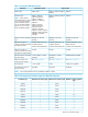
Table 1 Virtual LVI/LUN Specifications Parameter Track format Mainframe system 3380, 3390 Open system OPEN-3, OPEN-8, OPEN-9, OPEN-V OPEN-E Emulation type 3380-3, 3380-3A, OPEN-3, OPEN-8, OPEN-9, OPEN-V 3380-3B, 3380-3C, OPEN-E NOTE: The emulation 3380-F*, 3380-K*, types followed by an asterisk 3380-KA*, 3380-KB*, (*) can only be used with 3380-KC* Fujitsu mainframe systems.
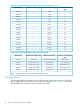
Table 2 CV Capacity by Emulation Types (for Mainframe System) (continued) Emulation type Minimum CV capacity (Cyl) Maximum CV capacity (Cyl) Number of control cylinders (Cyl) 3390-3A 1 3,339 6 3390-3B 1 3,339 6 3390-3C 1 3,339 6 3390-3R 1 3,339 6 3390-9 1 10,017 25 3390-9A 1 10,017 25 3390-9B 1 10,017 25 3390-9C 1 10,017 25 3390-L 1 32,760 23 3390-LA 1 32,760 23 3390-LB 1 32,760 23 3390-LC 1 32,760 23 3390-M 1 65,520 53 3390-MA 1 65,520 53 3390-MB
Table 4 SSID Requirements Controller emulation type SSID requirement 3990-6, 3990-6E (0104)x - (FFFD)x LVI/LUN Support 3390-3, 3390-3A, 3390-3B, 3390-3C, 3390-9, 3390-9A, 3390-9B, 3390-9C, OPEN-3, OPEN-8, OPEN-9, OPEN-E, and OPEN-V volumes 2105-F20, 2107 (0104)x - (FFFD)x 3380-3, 3380-3A, 3380-3B, 3380-3C, 3390-3, 3390-3A, 3390-3B, 3390-3C, 3390-3R, 3390-9, 3390-9A, 3390-9B, 3390-9C, 3390-L, 3390-LA, 3390-LB, 3390-LC, 3390-M, 3390-MA, 3390-MB, 3390-MC, OPEN-3, OPEN-8, OPEN-9, OPEN-E, and OPEN-V volum
In this manual, the sum of these two types of capacities is called the entire capacity. This section explains how to calculate the user area capacity and the entire capacity per CV. Implemented LDEVs consume this entire capacity from the VDEV capacity without exception. Therefore, even if the sum of user areas of multiple CVs and the user area of one CV are the same size, the free space generated when multiple CVs are created may be smaller than the free space generated when one CV is created.
NOTE: • ◦ The value enclosed in two upward arrows ( ) must be rounded up to the nearest whole number. ◦ The user area capacity is expressed in kilobytes ◦ The boundary value is expressed in kilobytes. The boundary value depends on the volume emulation types and RAID levels (see “Boundary Value for Each RAID Level” (page 17)).
NOTE: ◦ The value enclosed in two upward arrows ( ) must be rounded up to the nearest whole number. ◦ The user-specified CV capacity is expressed in blocks. ◦ The boundary value is expressed in kilobytes. The boundary value depends on the volume emulation types and RAID levels (see “Boundary Value for Each RAID Level” (page 17)).
NOTE: The user-specified CV capacity is expressed in blocks. To calculate the entire capacity of a CV, use the following formula. The resulting entire capacity is expressed in blocks. To convert the resulting entire capacity into megabytes, divide the capacity by 2,048. (user-specified-CV-capacity + management-area-capacity × 2) ÷ (boundary-value × 2) × (boundary-value × 2) NOTE: ◦ The value enclosed in two upward arrows ( ) must be rounded up to the nearest whole number.
NOTE: ◦ The value enclosed in two upward arrows ( ) must be rounded up to the nearest whole number. ◦ The calculated management area capacities depend on the volume emulation types and RAID levels (see “Calculated Management Area Capacities” (page 18)).
Table 6 Management Area Capacity of a Mainframe Volume (continued) Emulation Type Management Area Capacity 3380-F NOTE: 22 The management area capacity of a mainframe volume is expressed in cylinders. Table 7 Management Area Capacity of an Open-Systems Volume Emulation Type Management Area Capacity OPEN-V 0 OPEN-3 5,760 OPEN-8 19,440 OPEN-9 19,440 OPEN-E 13,680 NOTE: The management area capacity of an open-systems volume is expressed in kilobytes.
Table 10 Capacity of a Slot Emulation Type Capacity of a Slot 3380-xx, NF80-xx 48 3390-xx 58 OPEN-xx 48 (except for OPEN-V) OPEN-V 256 NOTE: • xx is a variable indicating one or more numbers or letters. • Slot capacity is expressed in kilobytes.
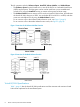
Figure 3 Parity Group Configuration As a result of VLL operations, a VDEV contains FVs, CVs, and free spaces that are delimited in logical cylinders. Sequential free spaces are combined into a single free space (see Figure 4 (page 19)). Figure 4 Virtual LVI/LUN Volume Configuration Overview of LDEV Formatting The LDEV Format feature allows you to format volumes (including external volumes). To format volumes, you must ensure that the volumes are in blocked status.
If the service processor (SVP) system option 503 is not set, when a volume is installed by using the following operations, the volume is formatted automatically: • Install CV • Volume Initialize • Make Volume If the SVP system option 503 is set, when a volume is installed by using the following operations, the volume is not formatted automatically, but is changed to Blocked. To format the installed volumes, see “Formatting the LDEVs” (page 79).
1. Zero-format the external mainframe volumes. The term zero-formatting refers to a formatting operation that writes the number 0 (zero) to the entire disk areas. For information on how to zero-format volumes, see the documentation for the mainframe system or the external storage system that you are using. 2. Use XP External Storage to perform mapping of zero-formatted external volumes and register the volumes in an external volume group.
• Volumes whose access attribute is not Read/Write • Quorum disks For details on how to execute the shredding function, see “Deleting the Data in the Target Volume” (page 90).
3 Preparing for Virtual LVI/LUN and Volume Shredder Operations This chapter describes the environment that you need to prepare in order to operate VLL and Volume Shredder.
4. 5. 6. 7. Right-click the target volume and select Blockade. A message appears asking if you want to change the volume status. Click OK to close the message. Information about the target volume is shown in blue bold italics. Click Apply. A message appears asking if you want to apply the settings. Click OK to close the message. The status of the volume changes to Blocked. NOTE: 24 • If you select Restore and click Apply, you can change the status of the volume from Blocked to Normal again.
4 Using the Virtual LVI/LUN and Volume Shredder GUI This chapter describes the Virtual LVI/LUN (VLL) and Volume Shredder GUI.
Figure 6 Customized Volume Window 26 Using the Virtual LVI/LUN and Volume Shredder GUI
Tree of Parity Groups and VDEVs • The tree of parity groups and VDEVs (on the left side of the Customized Volume window) shows the hierarchical structure of the storage system. For example, a disk group number (Box1), parity group number (1-1), RAID level (RAID1(2D+2D)), and VDEV number (1-1-(1)) are shown. ◦ If you open the Internal folder, the tree shows parity groups in the local storage system (that is, the storage system you are currently logged in to).
Table 14 LDEV Table Details Item Description Unit list Select the unit for which you want to show the volume capacity. • MB: Megabytes • Cyl: Cylinders • Block: Blocks When you manipulate mainframe volumes, you can only select Cyl. No. Volume number. LDKC:CU:LDEV A combination of a logical disk controller (LDKC) number, a control unit (CU) number, and a logical device (LDEV) number. Free indicates free space.
Table 14 LDEV Table Details (continued) Item Description Status The status of the volume: • Normal: The volume is in a normal status. • Blocked: The volume is in a blocked status. Hosts cannot access the blocked volume. • Warning: The volume has a problem. • Format: The volume is being formatted. • Preparing Quick Format: The volume is being prepared for Quick Format. • Normal (Quick Format): Quick Format is being executed on the volume.
Table 14 LDEV Table Details (continued) Item Description Encryption Opens the Encryption window. In the Encryption window, you can encrypt or decrypt parity groups. For details about encrypting or decrypting data in parity groups, see the HP StorageWorks XP24000/XP20000 Disk Encryption User Guide. Apply Implements the settings that have been made in this window.
• Select Restore from the pop-up menu • Click Apply in the Customized Volume window • Click Cancel in the Customized Volume window • Select File, and then select Refresh on the menu bar of the Remote Web Console main window The number of parity groups and LDEVs appear with the labels shown in Table 16 (page 31). Table 16 Displaying the Number of Parity Groups and LDEVs Label Remark PG Parity group. The number of the parity groups appearing in blue bold italics. LDEV LDEV.
Figure 7 Install CV Dialog Box (1) Item Description Parity Group VDEV number of the selected free space. The VDEV number indicates the parity group where the VDEV belongs. For example, if this field displays the VDEV number 1-1-(1), the VDEV belongs to a parity group numbered 1-1. • A VDEV number that starts with E (for example, E1–1–(1)) indicates that the VDEV belongs to a parity group that consists of one or more external LUs.
Item Description Specify capacity and number Select to specify the capacity and the number of CVs in the VLL volume that you want to create. Use the Capacity field to enter the capacity of the VLL volume in the unit selected in the Capacity Unit list. The available capacity range (minimum - maximum, for example, 46 - 6720 MB, 50 - 7168 Cyl, or 315 - 8513 blocks) is shown on the right. The value can be incremented by 1 MB, 1 cylinder, or 1 block.
Figure 8 Install CV Dialog Box (2) Item Description Parity Group Number of the VDEV to which the VLL volume belongs. The VDEV number indicates the parity group where the VDEV belongs. For example, if the VDEV number is 1-1-(1), the VDEV belongs to a parity group numbered 1-1. • A VDEV number that starts with E (for example, E1-1-(1)) indicates that the VDEV belongs to a parity group that consists of one or more external LUs.
Item Description Select LDKC No. Select an LDKC number from this list. The default is 00. The settings of LDEV numbers for the selected LDKC and CU numbers appear in the table on the left. • For an open-systems volume, you can select only 00. • For mainframe volumes of the following emulation types, you must not select 01: ◦ 3380-n, where n is a letter, a number, or a combination of both. However, you can select 01 if the emulation type is 3380-3, 3380-3A, 3380-3B, or 3380-3C.
Item Description Cancel Cancels the settings for the LDEV, and returns to the Customized Volume window. Clear Removes an LDKC:CU:LDEV number that is already assigned. To remove an LDKC:CU:LDEV number, select a VLL volume number corresponding to the LDKC:CU:LDEV number that you want to remove, right-click, and select Clear.
Figure 9 Set SSID (Install CV) Dialog Box Item Description Set SSID The Set SSID tree is a hierarchical structure of LDKC numbers (for example, LDKC00), CU numbers (for example, CU 00), SSID boundary areas (for example, 00-3F), and SSID (for example, 0004). A boundary area is a group of LDEV numbers to which an SSID is assigned. For example, if a boundary area is 00-FF, an SSID must be assigned to a group of LDEV numbers 00-FF.
Item Description The icons indicate the SSID boundary area assignments: An LDKC number or a CU number. SSIDs are assigned to all the boundary areas. An LDKC number or a CU number. SSIDs are assigned to all the boundary areas. An LDKC number or a CU number. SSIDs are not assigned to all the boundary areas. No SSID is assigned to this boundary area. SSID table Use this table to set the SSID boundary area. • LDKC: LDKC for the CU number that contains an LDEV boundary with no SSID.
Figure 10 Install CV Dialog Box (4) Item Description Parity Group Number of the VDEV to which the VLL volume belongs. The VDEV number indicates the parity group where the VDEV belongs. For example, if the VDEV number is 1-1-(1), the VDEV belongs to a parity group numbered 1-1. A VDEV number that starts with E (for example, E1-1-(1)) indicates that the VDEV belongs to a parity group that consists of one or more external LUs. System Disk Setting table System disk settings on the VLL volume. • No.
Item Description Release Releases the system disk settings from the selected VLL volume. Back Returns to the previous dialog box (that is, Install CV dialog box (2) or Set SSID (Install CV) dialog box). Next Opens the Install CV confirmation dialog box. Cancel Cancels the settings in this dialog box, and returns to the Customized Volume window. Install CV Confirmation Dialog Box Use the Install CV Confirmation dialog box to confirm the settings for the VLL volumes to be created.
Figure 11 Install CV Confirmation Dialog Box Item Description VDEV VDEV number for the VLL volume to be created. • A VDEV number that starts with E (for example, E1-1-(1)) indicates that the VDEV belongs to a parity group that consists of one or more external LUs. • A VDEV number that starts with V (for example, V1-1-(1)) indicates that the VDEV belongs to a parity group that consists of one or more XP Snapshot virtual volumes (V-VOLs).
Make Volume Dialog Box (1) Use the Make Volume dialog box (1) as the first dialog box to specify how to create the selected volume. Figure 12 Make Volume Dialog Box (1) Item Description Parity Group The VDEV number of the VLL volume to be initialized. The VDEV number indicates the parity group where the VDEV belongs. For example, if the VDEV number is 1-1-(1), the VDEV belongs to a parity group numbered 1-1.
Item Description Capacity Unit Select the unit to use for specifying the capacity of the VLL volume: • MB: Megabytes. This unit is used for specifying the capacity of open-system volumes. • Cyl: Cylinders. This unit is used for specifying the capacity of mainframe volumes. This unit can also be used for specifying the capacity of OPEN-V volumes. • Block: Blocks. This unit is used for specifying the capacity of external volumes.
Item Description Clear Deletes all the settings in the LDEV information table. Next Opens the Make Volume dialog box (2). When no CV is set, no volume will be made in the VDEV by the Make Volume operation. In this case, the dialog box returns to the Customized Volume window after a message appears. Cancel Cancels the selected settings and returns to the Customized Volume window.
Figure 13 Make Volume Dialog Box (2) Item Description Parity Group Number of the VDEV to be initialized. The VDEV number indicates the parity group where the VDEV belongs. For example, if the VDEV number is 1-1-(1), the VDEV belongs to a parity group numbered 1-1. • A VDEV number that starts with E (for example, E1-1-(1)) indicates that the VDEV belongs to a parity group that consists of one or more external LUs.
Item Description Select LDEV No. area Use this area to set LDEV numbers for the VLL volumes you intend to create. • Select LDKC No.: Select an LDKC number from the list. The default is 00. The settings of LDEV numbers for the selected LDKC and CU numbers appear in the Select LDEV No. table. • Select CU No.: Select a CU number from the list. The default is CU 00. The settings of LDEV numbers for the selected CU number appear in the Select LDEV No. table.
Set SSID (Make Volume) Dialog Box The Set SSID (Make Volume) dialog box opens during the creation of VLL volumes if the boundary area of the selected LDEV number does not have an SSID. Use this dialog box to set an SSID.
Figure 14 Set SSID (Make Volume) Dialog Box Item Description Set SSID tree A hierarchical structure of LDKC numbers (for example, LDKC00), CU numbers (for example, CU 00), SSID boundary areas (for example, 00-3F), and SSID (for example, 0004). A boundary area is a group of LDEV numbers to which an SSID is assigned. For example, if a boundary area is 00-FF, an SSID must be assigned to a group of LDEV numbers 00-FF.
Item Description The icons indicate the SSID boundary area assignments. An LDKC number or a CU number. SSIDs are assigned to all the boundary areas. An LDKC number or a CU number. SSIDs are assigned to all the boundary areas. An LDKC number or a CU number. SSIDs are not assigned to all the boundary areas. No SSID is assigned to this boundary area. SSID table Use this table to set the SSID boundary area. • LDKC: LDKC for the CU number that contains an LDEV boundary with no SSID.
Figure 15 Make Volume Dialog Box (4) Item Description Parity Group Number of the VDEV to which the VLL volume belongs. The VDEV number indicates the parity group where the VDEV belongs. For example, if the VDEV number is 1-1-(1), the VDEV belongs to a parity group numbered 1-1. A VDEV number starting with E (for example, E1-1-(1)) indicates that the VDEV belongs to a parity group that consists of one or more external LUs. System Disk Setting Shows system disk settings on the VLL volume. • No.
Item Description Back Returns to the previous dialog box (that is, Make Volume dialog box (2) or Set SSID (Make Volume) dialog box). Next Opens the Make Volume confirmation dialog box. Cancel Cancels the settings in this dialog box, and returns to the Customized Volume window. Make Volume Confirmation Dialog Box Use the Make Volume confirmation dialog box to confirm the settings of the VLL volumes to be created. The VLL volume-setting information table shows a list of VLL volumes to be created.
Item Description LDKC:CU:LDEV The LDKC number, the CU number, and the LDEV number of the VLL volume to be created. Option Shows System Disk if the VLL volume is configured as a system disk. Back Returns to the previous dialog box. OK Registers the Make Volume settings, and returns to the Customized Volume window. Cancel Cancels the Make Volume settings, and returns to the Customized Volume window.
Figure 17 Volume Initialize Dialog Box (1) Item Description Parity Group Number of the VDEV to be initialized. The VDEV number indicates the parity group where the VDEV belongs. For example, if the VDEV number is 1-1-(1), the VDEV belongs to a parity group numbered 1-1. • A VDEV number starting with E (for example, E1-1-(1)) indicates that the VDEV belongs to a parity group consisting of one or more external LUs.
Item Description Select LDEV No. area Allows you to set LDEV numbers for the VLL volume to be initialized. • Select LDKC No.: Select an LDKC number from the list. The default is 00. The settings of LDEV numbers for the selected LDKC and CU numbers appear in the Select LDEV No. table. • Select CU No.: Select a CU number from the list. The default is CU 00. The settings of LDEV numbers for the selected CU number appear in the Select LDEV No. table.
Volume Initialize (Set SSID) Dialog Box The Volume Initialize (Set SSID) dialog box opens during the initialization of VLL volumes if the boundary area of the selected LDEV number does not have an SSID. Use this dialog box to set an SSID.
Figure 18 Volume Initialize (Set SSID) Dialog Box Item Description Set SSID tree A hierarchical structure of LDKC numbers (for example, LDKC00), CU numbers (for example, CU 00), SSID boundary areas (for example, 00-3F), and SSID (for example, 0004). A boundary area is a group of LDEV numbers to which an SSID is assigned. For example, if a boundary area is 00-FF, an SSID must be assigned to a group of LDEV numbers 00-FF.
Item Description The icons indicate the SSID boundary area assignments. An LDKC number or a CU number. SSIDs are assigned to all the boundary areas. An LDKC number or a CU number. SSIDs are assigned to all the boundary areas. An LDKC number or a CU number. SSIDs are not assigned to all the boundary areas. No SSID is assigned to this boundary area. SSID table Use this table to set the SSID boundary area. • LDKC: LDKC for the CU number that contains an LDEV boundary with no SSID.
Figure 19 Volume Initialize Confirmation Dialog Box (for Confirming Volume Initialize Settings) Item Description VDEV VDEV number for the VLL volume to be initialized. • A VDEV number starting with E (for example, E1-1-(1)) indicates that the VDEV belongs to a parity group consisting of one or more external LUs. • A VDEV number starting with V (for example, V1-1-(1)) indicates that the VDEV belongs to a parity group consisting of one or more XP Snapshot virtual volumes (V-VOLs).
RAID Concatenation Dialog Box In the storage system, data can be written to an LDEV that extends over concatenated parity groups; concatenation of parity groups enables faster access to data. Use the RAID Concatenation dialog box to see a list of the concatenated parity groups on your storage system. Figure 20 RAID Concatenation Dialog Box Item Description VDEV A list of concatenated parity groups on your storage system. Close Closes the RAID Concatenation dialog box.
Figure 21 Format All Dialog Box Item Description Action Select the action to perform. • Format: Volumes will be formatted. • Write To Control Blocks: Control blocks in external mainframe volumes will be overwritten. Parity Group Type Select the type of parity group. • Internal: The operation will be performed on internal volumes. • External: The operation will be performed on external volumes. If Action is Write To Control Blocks, Parity Group Type is always External.
Item Description OK Confirms the settings in the Format All dialog box, and closes this dialog box. If an external volume to be operated is disconnected, the external volume must be omitted from the operation target. Cancel Cancels the settings in the Format All dialog box, and closes this dialog box. Shredding Param. Dialog Box Use this dialog box to define the settings of the shredding operation. To open the Shredding Param. dialog box, click Shredding Param. in the Customized Volume window.
Figure 22 Shredding Param. Dialog Box Item Description Write Data Type Select whether to use the default settings of the shredding operation or to define the settings of the shredding operation yourself. • Default (00-FF-00) — The default settings will be adopted. The default settings allow you to delete data in a volume by overwriting the volume three times with dummy data.
Item Description Select the contents of the dummy data. • Define — You can enter numbers or characters in the text box, and the data you enter will be used as the dummy data. You can enter only hexadecimal numbers in this text box. Therefore, you can use numbers from 0 to 9 and letters from A to F. You can enter up to 4 digits. • Random — Volume Shredder will select 4-digit hexadecimal numbers at random for the dummy data. The dummy data will be written two digits each.
number is 11. The filename also indicates that dummy data has been written to that volume three times. A binary file contains the first 512 bytes of data of a shredded volume (LDEV). The text file contains the following summary information for a shredding operation: • Results of a shredding operation • Contents of the dummy data • Shredded volumes • Start and finish time of a shredding operation The file name of a text file is displayed as follows: shread_the-finish-time-of-shredding-operation.
Table 18 Ending Status of a Shredding Operation (continued) Ending Status Displayed in the Dialog Box Meaning Shredding data transfer error The result of the shredding operation could not be output to a file. Shredding data verify error An error was detected while verifying the file containing the result of the shredding operation. No-data assigned.
Figure 24 Shredding Data Output Dialog Box Item Description non-object Volume The result of shredding the volumes in this list will NOT be saved in files. Each row represents one volume. Each volume shows the LDKC number, the CU number, and the LDEV number, delimited by a colon (:). object Volume The result of shredding the volumes in this list will be saved in files. Each row represents one volume. Each volume shows the LDKC number, the CU number, and the LDEV number, delimited by a colon (:).
Figure 25 Select Progress Dialog Box 1 Figure 26 Select Progress Dialog Box 2 Item Description Select Progress Select one operation and click OK to view progress information about the selected operation. • Format: Indicates formatting is in progress. • Shredding: Indicates shredding is in progress. • Preparing Quick Format: Indicates preparation for Quick Format is in progress. OK Closes the dialog box, and shows the progress about the selected operation.
Figure 27 System Disk Options Dialog Box Item Description Additional configuration Back up Enable is selected while you are using this function. To make it unavailable, select Disable. To make it available, select Enable. If you enable this function, it takes up to 12 minutes longer to turn a power supply on and up to 15 longer to turn a power supply off. Plan for the additional time on storage system operation when you turn on or off the power supply of the storage system.
5 Performing Virtual LVI/LUN and Volume Shredder Operations This section describes procedures for performing VLL operations and Volume Shredder operations. • “Virtual LVI/LUN Operations” (page 69) • “Volume Shredder Operations (For Volumes Using Hard Disk)” (page 89) Virtual LVI/LUN Operations You must have write permission for VLL. For details on assigning user access, see the HP StorageWorks XP24000/XP20000 Remote Web Console User Guide.
Converting Logical Volumes to Space WARNING! The Volume to Space function is a destructive operation. The data on the logical volumes being converted is lost when the operation is complete. The user is responsible for backing up the data as needed before performing this operation. The Volume to Space function allows you to convert one or more logical volumes (LDEVs) to space, which deletes the selected LDEVs from that VDEV.
6. 7. In the confirmation panel, click OK. The conversion to space starts. When the conversion ends, a message appears. Click OK to close the message. CAUTION: When the Volume to Space function is performed, the alias information that is set to the specified LDEV is also deleted. If you set the alias to the LDEV, you must migrate the alias information to another LDEV before the Volume to Space function is performed, or you must reconfigure the alias after the Volume to Space function is performed.
c. Specify the capacity of the VLL volume and/or the number of CVs according to the selected method. For example: • If you select Specify capacity and number, enter the capacity in the Capacity box, and then enter the number of CVs in the No. box. • If you select Divide free space by number, enter the number of CVs in the No. box. • If you select Divide free space by capacity, enter the capacity in the Capacity box. • If you select Set remaining space as volume, go to the next step.
11. To set other VLL volumes, repeat steps 8 through 10. To remove an LDKC:CU:LDEV number that is already assigned, select one or more VLL volume numbers corresponding to the LDKC:CU:LDEV numbers that you want to remove. Then right-click, and select Clear. 12. After setting all CU numbers and LDEV numbers, click Next. If the boundary area of the selected LDEV number does not have an SSID, the SSID setting dialog box appears. Go to step 13.
Converting CVs Back to FVs (Volume Initialize Operation) WARNING! The Volume Initialize function is a destructive operation. The data on the Virtual LVI/LUN volume being converted is lost when the operation is complete. The user is responsible for backing up the data as needed before performing this operation. The Volume Initialize function allows you to convert a Virtual LVI/LUN volume back to a fixed volume.
c. d. 5. Select an LDEV number from the white LDEV numbers in the Select LDEV Number table. The LDKC number, CU number, and LDEV number appear in the LDKC:CU:LDEV field. To change an LDKC:CU:LDEV number that is already assigned, select one or more volume numbers corresponding to the LDKC:CU:LDEV numbers that you want to remove, and then right-click and select Clear. After setting all CU numbers and LDEV numbers, click Next.
Re-creating the CVs After Initializing the VDEV (Make Volume Operation) WARNING! The Make Volume function is a destructive operation. The data on the Virtual LVI/LUN volume being converted is lost when the operation is complete. The user is responsible for backing up the data as needed before performing this operation. The Make Volume operation deletes all volumes in a VDEV and creates new variable-sized volumes (CVs).
1. Make sure that Remote Web Console is in Modify mode. For detailed information about Modify mode, see the HP StorageWorks XP24000/XP20000 Remote Web Console User Guide. 2. In the tree on the left side of the Customized Volume window, open a folder, and select the desired disk group, parity group, and VDEV. The table on the right side of the window shows detailed information about the LDEVs of the selected VDEV.
b. c. can be incremented by 1 MB or 1 block for open systems or by 1 Cyl for mainframe systems. Click Set to display the setting in the How to create volume table. To remove VLL volume settings displayed in the How to create volume table, do the following: • To remove a setting, select the VLL volume, and click Delete. When a confirmation message appears, click OK. • To remove all settings, click Clear. When a confirmation message appears, click OK.
22. To apply the changes to the storage system, click Apply (or Cancel to cancel them). While an LDEV is being formatted, a progress window is displayed. The percentage of completion displayed might be 0% or 99%. This completion percentage could remain visible while the format operation is in progress. If desired, you can make settings on the Volume Initialize function (see “Converting CVs Back to FVs (Volume Initialize Operation)” (page 74) before clicking Apply.
4. 5. Confirm that the status of the volume under the Status column of the LDEV Information table in the Customized Volume window is now changed to Blocked, and all the information for this volume is displayed in blue bold italics. Click Apply in the Customized Volume window, and then click OK on the confirmation dialog box. The new setting will be implemented on the storage system and a notification dialog box will appear to notify you that the implementation has been completed.
If volumes appear in blue bold italics on the LDEV information table, do either of the following to re-operate the volumes: • Click Apply or Cancel. • Right-click the volume displayed in blue bold italics and select Reset . Formatting All Volumes in Disk Groups or Parity Groups This section describes how to format all volumes in disk groups or parity groups.
9. Click OK to close the Format All dialog box. A message appears asking if you want to apply the settings. 10. Click OK to start formatting. Quick Formatting the LDEVs The Quick Format feature allows you to execute the quick formatting operation on internal volumes. To execute quick formatting on an internal volume, you must make sure the internal volume is in blocked status according to the instructions in “Blocking Internal Volumes” (page 85).
Table 20 Quick Format Specifications (continued) Items Description Storage system is powered off and then you turn the power back on. The Quick Format operation resumes if you turn the power back on. Restrictions • Quick Format cannot be executed on external volumes, virtual volumes, system disks, journal volumes of XP Continuous Access Journal, and quorum disks. • The XP Auto LUN feature or the QuickRestore feature cannot be applied to volumes undergoing Quick Format.
• The required time shown in Table 22 (page 83) might be as much as four times longer, depending on the configuration of disk adapter (DKA) pairs. • When you execute quick formatting at the same time on multiple parity groups that have different drive capacities, calculate the required time for the parity group that has the largest capacity. Host performance might be affected during the execution of quick formatting. Table 23 (page 84) indicates the estimated performance of a host.
the audit log in a system disk, your system disk should have 176 megabytes or more of disk capacity. The following rules apply when creating system disks: • Normal data cannot be stored in system disks. • You can create only 16 volumes for system disks in the entire storage system. • HP recommends that you create system disks in internal volumes even though you can also create system disks in external volumes. • There is no restriction on the emulation type for system disks.
4. 5. Confirm that the status of the volume under the Status column of the LDEV Information table in the Customized Volume window is now changed to Blocked, and all the information for this volume is displayed in blue bold italics. Click Apply in the Customized Volume window. The message to confirm whether to block an internal volume will be displayed. Click OK after confirming the message. Then click OK on the confirmation dialog box.
If volumes appear in blue bold italics on the LDEV information table, do either of the following to re-operate the volumes: • Click Apply or Cancel. • Right-click the volume displayed in blue bold italics and select Reset. Making External Mainframe Volumes Usable The following procedure enables you to make external mainframe volumes usable. 1. 2. 3. Zero-format external mainframe volumes.
6. Click Apply in the Customized Volume window, and then click OK on the confirmation dialog box. The new setting will then be implemented on the storage system, and a notification dialog box will appear to notify you that the implementation has been completed. Click OK on the notification dialog box. 7. Confirm that the status of the volume is now displayed as Blocked under the Status column of the LDEV Information table in the Customized Volume window. 8.
When the Format All dialog box is displayed, all entries in the Action column are Write To Control Blocks, which means that control blocks in all the disk groups or all the parity groups will be overwritten. If you change the selection in Target when any of the entries in the Action column are empty, all the entries in the Action column will change to Write To Control Blocks. 8. 9. Click OK to close the Format All dialog box. A message appears and asks if you want to apply the settings.
Format List become equal to N, the number of shredding operations, including the Last Data row. The number of rows = The number of shredding operations to perform. N = The number of shredding operations necessary to overwrite data in target volume with dummy data (see “ Calculating the Number of Shredding Operations Necessary to Overwrite Data in Target Volume with Dummy Data to Delete” (page 93)).
6. Use the Shredding Data Output dialog box to specify how Volume Shredder will save information about the result of shredding the volumes. When specifying it, see the following instructions: • To save the result of shredding a volume, you must ensure that the volume is displayed in the object Volume list. If the volume is not displayed in the list, select the volume from the non-object Volume list, and then click Add. The volume will be added to the object Volume list.
Canceling Data Deleting During the shredding operation, the following message box appears. To cancel shredding during the operation, click Cancel in this message box. Figure 30 Message Dialog Displayed During the Shredding Operation If you click Close, the progress of the shredding operation will not be displayed but the shredding operation continues. To re-display progress, click Progress in the Customized Volume window.
NOTE: Data deleting conforming to DoD5220.22-M for a volume using a flash disk is enabled by performing multiple dummy data overwriting while changing the data pattern. For the method to change the data pattern, see “Shredding Param. Dialog Box” (page 61) and “Defining the Shredding Settings” (page 89). In addition, a sample data deleting conforming to DoD5220.22-M is shown in “ Calculating the Number of Shredding Operations Necessary to Overwrite Data in Target Volume with Dummy Data to Delete” (page 93).
2.
6 Troubleshooting This chapter explains how to troubleshoot problems that you might experience while using Virtual LVI/LUN or Volume Shredder. • “Troubleshooting” (page 95) • “Calling HP Technical Support” (page 95) Troubleshooting • For troubleshooting information on the storage system, see the HP StorageWorks XP24000/XP20000 Disk Array Owner Guide. • For troubleshooting information on the Remote Web Console software, see the HP StorageWorks XP24000/XP20000 Remote Web Console User Guide.
7 Support and Other Resources Related Documentation • HP StorageWorks XP24000/XP20000 Cache Residency Manager User Guide • HP StorageWorks XP24000/XP20000 Snapshot User Guide • HP StorageWorks XP24000/XP20000 Thin Provisioning Software User Guide • HP StorageWorks XP24000/XP20000 LUN Manager User Guide • HP StorageWorks XP24000/XP20000 Remote Web Console Error Codes • HP StorageWorks XP24000/XP20000 Remote Web Console User Guide • HP StorageWorks XP24000/XP20000 External Storage Software User G
Before contacting HP, collect the following information: • Product model names and numbers • Technical support registration number (if applicable) • Product serial numbers • Error messages • Operating system type and revision level • Detailed questions Subscription Service HP recommends that you register your product at the Subscriber’s Choice for Business website: http://www.hp.
Glossary C cache extents areas used for Cache Residency Manager Cache Residency Manager dynamic cache residency CU Control unit. CV customized volume D DKC Disk controller. F FV fixed-size volume J JNL journal L LD, LDEV Logical device. An LDEV is created when a RAID group is carved into pieces according to the selected host emulation mode (that is, OPEN-3, OPEN-8, OPEN-9). The number of resulting LDEVs depends on the selected emulation mode. The term LDEV is also known as term volume.
S SATA Serial Advanced Technology Attachment. SIM Service information message. SLPR Storage logical partition. SSID storage system ID SSID Subsystem identifier; storage system identifier. SVP service processor SVP Service processor. A computer built into a disk array. The SVP, used only by an HP service representative, provides a direct interface to the disk array. T TB Terabyte. Equivalent to 1,000 Gb for data storage and statistics, or 1,024 Gb for memory.
Index B boundary limitation, 18 C Concatenation List, 69 conventions storage capacity values, 96 converting logical volumes to space, 70 normal volumes to free space, 70 Customized Volume window, 25 changes, 73 Format All dialog box, 59 Install CV confirmation dialog box, 40 Install CV dialog box (2), 33 Install CV dialog box (4), 38 Install CV dialog boxes (1), 31 Make Volume confirmation dialog box, 51 Make Volume dialog box (2), 44 Make Volume dialog box (4), 49 parity group status icons, 27 Set SSID (I
conventions, 96 storage systems supported models, 6 Subscriber's Choice, HP, 97 system requirements Virtual LVI/LUN (VLL), 23 Volume Shredder, 23 W websites HP, 97 HP Subscriber's Choice for Business, 97 product manuals, 96 T technical support, 97 calling, 95 HP, 96 troubleshooting, 95 U unique SSID, 10 V VDEV, 7 VDEV status icons, 27 VDEV volume configuration, 19 Virtual LVI/LUN (VLL) creating VLL volumes, 71 deleting VLL volumes, 73 functions, 7 Install CV function, 8 launching, 69 LUSE specifications