HP XP P9000 Continuous Access Synchronous User Guide Abstract This guide explains how to use HP XP P9000 Continuous Access Synchronous Software to protect information stored on HP XP P9000 disk arrays from local disaster by continuously copying local data across Fibre Channel (FC) connections to remote HP XP P9000 disk arrays.
© Copyright 2010, 2014 Hewlett-Packard Development Company, L.P. Confidential computer software. Valid license from HP required for possession, use or copying. Consistent with FAR 12.211 and 12.212, Commercial Computer Software, Computer Software Documentation, and Technical Data for Commercial Items are licensed to the U.S. Government under vendor's standard commercial license. The information contained herein is subject to change without notice.
Contents 1 Continuous Access Synchronous overview......................................................7 How Continuous Access Synchronous works ................................................................................7 Typical components .................................................................................................................7 Storage systems........................................................................................................................
Direct connection..........................................................................................................34 Switch connection.........................................................................................................34 Extender connection......................................................................................................35 Ports.................................................................................................................................
Example of an exported text file...........................................................................................70 Changing Fence Level.............................................................................................................71 RCU maintenance...................................................................................................................71 Changing Minimum Paths, Round Trip Time, Wait Time...........................................................
Add RCU (Fibre) dialog box...................................................................................................111 RCU Option dialog box.........................................................................................................112 Add Path(Fibre) dialog box....................................................................................................113 Add SSID dialog box........................................................................................................
1 Continuous Access Synchronous overview A Continuous Access Synchronous (Cnt Ac-S) system creates and maintains a mirror image of a production volume at a remote location. Data in a Continuous Access Synchronous backup stays synchronized with the data in the local XP P9500 storage system. This happens when data is written from the host to the local storage system then to the remote storage system, via the Fibre Channel data path.
recovery. If this is not possible, the local host must be in communication with the secondary system. • A primary volume (P-VOL) on the local storage system that is copied to the secondary volume (S-VOL) on the secondary system. The primary and secondary volumes may be composed of expanded LUs using LUN Expansion. • Fibre Channel data paths for data transfer between primary and secondary systems. • Target, initiator, and RCU target ports for the Fibre Channel interface.
Volume pairs As described previously, original data is stored in the P-VOL and the remote copy is stored in the S-VOL. The pair can be split, resynchronized, reverse resynchronized, and returned to SMPL status. • When paired, the volumes are synchronized. • When split, new data is sent to the P-VOL but not the S-VOL. • When resynchronized, data that changed while the pair was split is copied to the S-VOL. • When necessary, data in the S-VOL can be copied to the P-VOL.
Failover software Host failover software is used to transfer information between host servers at the local and remote sites. It is a critical component of any disaster recovery solution. • When Continuous Access Synchronous is used as a disaster recovery tool, host failover is required to ensure effective recovery operations. • When Continuous Access Synchronous is used as a data migration tool, host failover is recommended. Continuous Access Synchronous does not provide host failover functions.
Update copy If the host issues an update after the initial copy is complete, the data is written to the P-VOL and copied to the S-VOL. Subsequent updates are held until the current update is completed in both volumes. This keeps the pair synchronized. Update copy has a higher priority than initial copy. However, if an initial copy is in progress when updates are sent by the host, the update copy must wait until the initial copy’s copy pace completes.
2 Requirements and specifications This chapter provides basic system requirements. In addition to the information here, Planning for Continuous Access Synchronous (page 15) provides many specifications, recommendations, and restrictions for the elements of a Continuous Access Synchronous system that require attention before setting up and using Continuous Access Synchronous. System requirements and specifications The following table describes general system requirements.
Item Requirement Logical paths • Maximum of eight logical paths supported from primary system to secondary system. • Logical paths are established separately for primary and secondary system CUs. • Maximum number of logical paths allowed for a primary system is 32 (8 paths per secondary system X 4 secondary system per primary system). Path group Groups of logical paths, which allows you to configure or change the configuration of multiple paths at the same time.
Item Requirement Host failover software • Required for disaster recovery. • Recommended for data migration. See “Host failover software” (page 33) for more information. Interfaces • Remote Web Console is required. ◦ The following RWC roles are required to operate: - Storage Administrator (Remote Copy) - Storage Administrator (System Resource Management) - Storage Administrator (Provisioning) ◦ The primary system must be LAN-attached to a Remote Web Console computer.
3 Planning for Continuous Access Synchronous This chapter provides information and instructions for planning primary and secondary system, pair volumes, data paths, and other elements. Storage system preparation The following preparations are required for the storage systems in a Continuous Access Synchronous pair relationship. • You can pair the volumes on XP P9500 with volumes on another XP P9500, XP24000/XP20000 Disk Array, or XP12000 Disk Array/XP10000 Disk Array.
storage systems. In that case, pair volumes on a XP P9500 cannot be paired with volumes on XP24000/XP20000 Disk Array and XP12000 Disk Array/XP10000 Disk Array.
Option mode Description Do not set this mode if the local storage system is connected to XP12000 Disk Array, XP10000 Disk Array, or earlier models, or to XP24000/XP20000 Disk Array with microcode earlier than 60-02-XX-XX/XX; otherwise Continuous Access Synchronous pairs may suspend. 784 Allows you to reduce RIO MIH time to 5-seconds. As a result, after a data path error, the total amount of time that elapses is reduced before the operation is retried on an alternate path.
Note the following Round Trip Time considerations: • If the difference between Round Trip Time and remote IO response time is significant, the system slows or even interrupts the initial copy operation so that the update copy can continue. Example of significant difference between the two: 1ms RT Time : 500ms remote IO response time. • If the difference between the two is insignificant, initial copying is allowed to run at the specified pace.
The following table shows example settings. Round trip time between MCU RCU [ms] Data path speed Number of data between paths between MCU/RCU MCU/RCU (MB/ms) Initial copy pace Number of maximum initial copy VOLs Round trip time specified [ms] 0 0.1 4 15 64 160 30 0.1 4 15 64 220 100 0.1 4 15 64 360 Planning for pairs and pair volumes This section discusses requirements, options, and settings you need for setting up pairs and pair volumes.
• Continuous Access Synchronous supports LUN Expansion (LUSE). This allows you to configure expanded LUs using two or more contiguous LDEVs (up to 36). ◦ If two LUSE volumes are paired with Continuous Access Synchronous, a LUSE P-VOL must be paired with an S-VOL of the same size and structure. For example, if a LUSE P-VOL is connected with volumes of 1GB, 2GB, and 3GB in this order, you must specify a LUSE volume that has exactly the same size and the same connection order as the S-VOL.
and P-VOL track maps keep track of differential data and are used to re-synchronize the pair. Enabling S-VOL-write is done during the pairsplit operation. • The S-VOL write option is available when the split operation is performed from the primary system. • When you resync a pair with the S-VOL write option enabled, the secondary system sends S-VOL differential data to the primary system.
When you start the initial copy, you will specify whether to manage differential data by Tracks or Cylinders. In Remote Web Console, you also have the Auto option. With Auto, either Cylinder or Track is used, depending on the basic size of the LU. • When managing differential data by cylinders, sharing volumes with Compatible FlashCopy is restricted. See the HP XP P9000 for Compatible FlashCopy Mirroring User Guide for more information.
Procedure 1 To calculate the maximum number of pairs 1. Calculate the number of cylinders. 1. Calculate the system’s number of logical blocks, which is the volume’s capacity measured in blocks. Number of logical blocks = Volume capacity (bytes) / 512 2. Calculate the number of cylinders: For OPEN-3, OPEN-8, OPEN-9, OPEN-E, OPEN-L, OPEN-K: Number of cylinders = ceil ( (ceil (Number of logical blocks / 96) ) / 15) For OPEN-V. Number of cylinders = ceil ( (ceil (Number of logical blocks / 512) ) / 15) 2.
3. Calculate the maximum number of pairs, which is restricted by the following: • The number of bitmap areas required for Continuous Access Synchronous (calculated above). • The total number of bitmap areas in the storage system, which is 65,536. Bitmap areas are also used by Continuous Access Synchronous Z, Continuous Access Journal, Continuous Access Journal Z, and External Storage Access Manager.
In this case, because the value of Maximum Initial Copy Activities is 2, initial copy operations for LUN 02 and LUN 00 are started. If either one of the initial copy operations for LUN 02 and LUN 00 is completed, the initial copy for LUN 01 is started. Example 2: initial copy started, new pairs added The following table shows the Priority value when the initial copy is already begun and then two new pairs are added. The P-VOLs are for the new pairs.
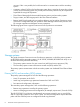
Figure notes: • Cnt Ac-S pairs are assigned to a consistency group using RAID Manager. Cnt Ac-S Z pairs are assigned to a consistency group using Business Continuity Manager (BCM). • Open and mainframe primary volumes (P-VOLs/M-VOLs) receive I/O requests from their applications at the primary (main) site, and data in the volumes is updated. • Cnt Ac-S or Cnt Ac-S Z runs copy operations in the consistency group.
Figure notes: • RAID Manager manages the consistency group on all primary and secondary system. Business Continuity Manager cannot be used with multiple systems. • Open and mainframe volumes (P-VOLs/M-VOLs) receive I/O requests from their applications at the primary (main) site, and data in the volumes is updated. • Continuous Access Synchronous or Continuous Access Synchronous Z runs the copy operation in the consistency group.
• Pair operations can be performed from RAID Manager only. Business Continuity Manager and Remote Web Console do not support pair operations for pairs in a CTG with multiple XP P9500s. • Cascade configurations with Continuous Access Journal pairs is not supported. Assigning pairs to a consistency group Pairs are assigned to a consistency group (CTG) during the Paircreate operation.
Using an existing CTG You can assign new pairs or existing pairs to an existing consistency group. Procedure 4 To assign new pairs to an existing consistency group 1. 2. 3. Add Cnt Ac-S and Cnt Ac-S Z pair information to the existing configuration definition file B, which consists of pairs in multiple XP P9500s. Copy and create RAID Manager configuration definition file C. Perform the paircreate operation for Cnt Ac-S and Cnt Ac-S Z pairs and register them to configuration definition file C.
• If a split or suspend operation is in progress when I/O processing on Cnt Ac-S or Cnt Ac-S Z pairs begins, the split operation on the pairs is given priority. After the pair is split, then the I/O processing begins. • Data consistency cannot be ensured when all of the following conditions exist: - A port is blocked. - A split command is in progress. - I/O processing begins. In such a case, resynchronize the consistency group and then run the split command again.
Pair status before and after a split operation Pairs in the same consistency group must be in PAIR/Duplex status when you begin the split operation in order to maintain consistency. Otherwise, when the operation completes, pair status will be inconsistent.
CTG 127 behavior and restrictions when a pair is suspended Note the following behaviors and restrictions regarding the consistent suspending of all P-VOLs when a pair suspends. • When a failure occurs or if a pair is suspended by RAID Manager, all P-VOLs will be suspended. • When P-VOLs and S-VOLs are registered in CTG 127, and both volumes are paired bi-directionally, all of the target pair volumes are registered in CTG No.127 when takeover takes place.
• If all the data paths for Continuous Access Synchronous pairs are disconnected, but the paths used for Cnt Ac-J pairs are connected, failure suspend does not occur and S-VOLs cannot be changed to PSUE status. • If you turn off the power of the primary system when S-VOLs are in PAIR status, all the data paths for the primary system will be disconnected and all the S-VOLs registered in CTG 127 will be changed to PSUE status.
With Fibre Channel connections, you can use the switches as ordinary switch connections. No special settings are required for the HP XP P9500. Direct connections up to 10 km with single-mode longwave Fibre Channel interface cables are supported. Link speed determines the maximum distance you can transfer data and still achieve good performance. The following table shows maximum distances at which performance is maintained per link speed, over single-mode longwave Fibre Channel.
• • Set port topology to the following: ◦ NL port: Fab on, FC-AL ◦ N port: Fab on, Point-to-Point ◦ Some switch vendors require F port (for example, McData ED5000). Host I/O response time can be improved on long distance switch connections by using host mode options 49 and 50, or 51 and 65. The following table describes these options for the 8UFC or 16UFC package. A HP-approved channel extender is required.
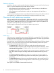
Figure 1 Extender Connection • Set port topology to the following: ◦ NL/FL port: Fab on, FC-AL ◦ F port: Fab on, Point-to-Point • Best practice is to create at least two independent data paths (one per cluster) between the primary and secondary system for hardware redundancy for this critical element.
Target ports must be configured on the primary system for Continuous Access Synchronous operations. • External port: Required for External Storage copy operations. This port is not used for Continuous Access Synchronous copy operations. This port can be changed to a target, initiator, or RCU target port.
4 Sharing Continuous Access Synchronous volumes This chapter helps you plan Continuous Access Synchronous pair volumes when they are shared with non-Continuous Access Synchronous volumes. All the software products that can be used with Continuous Access Synchronous (Cnt Ac-S) are discussed here. Volume types that can be shared with Continuous Access Synchronous The following table shows when volumes used by other software can also be used as Cnt Ac-S P-VOLs and S-VOLs.
Volume type Used as Cnt Ac-S P-VOL? Used as Cnt Ac-S S-VOL? P-VOL in PSUS (Delete pair to RCU) status Yes Yes P-VOL in COPY(RS-R)/RCPY status No No BC P-VOL is also used as a Cnt Ac-J P-VOL or S-VOL No No P-VOL (none of the above) Yes Yes S-VOL in PSUS (Delete pair to RCU) status Yes No S-VOL (none of the above) No No Reserved volume No No Business Copy (BC) Continuous Access Journal (Cnt Ac-J) P-VOL in COPY status No No P-VOL in PAIR status 2 Yes No3 P-VOL in PSUS (Delete pa
Data Retention You can create a Continuous Access Synchronous pair using volumes that have been assigned the access attribute by the Data Retention (DRU). However, you cannot specify a volume with the “S-VOL Disable” attribute as a Continuous Access Synchronous S-VOL. The following table shows whether a DRU volume with the specified access attribute can be used as a Continuous Access Synchronous P-VOL or S-VOL.
The following tables show Cnt Ac-S volumes and status with the Data Retention operations that can be performed using Remote Web Console and RAID Manager.
LUN Expansion LUSE volumes can be assigned to Continuous Access Synchronous pairs, with the following restrictions: • The P-VOL and S-VOL must have the same LU type and the same number of LDEVs. • If you need to perform LUSE operations on an existing Continuous Access Synchronous P-VOL or S-VOL, you must release the pair first to return the volume to SMPL status.
Business Copy Business Copy volumes can be assigned to Continuous Access Synchronous pairs, and Continuous Access Synchronous volumes can be assigned to Business Copy pairs. The following table shows the configurations that are possible. Continuous Access Synchronous volume BC P-VOL BC S-VOL P-VOL Yes Yes S-VOL Yes No Please note the following when sharing Continuous Access Synchronous volumes with Business Copy volumes.
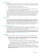
Figure 3 Shared Cnt Ac-S S-VOL with BC P-VOL • In the following figure, the configurations shown in the previous two figures are combined. Both the Continuous Access Synchronous P-VOL and S-VOL function as Business Copy P-VOLs, providing multiple copies at the local and remote sites. Figure 4 Shared Cnt Ac-S P-VOL, S-VOL with multiple BC P-VOLs Configurations with Business Copy S-VOLs In the following figure, a Business Copy S-VOL also functions as a Continuous Access Synchronous P-VOL.
• Continuous Access Synchronous pair status is reported to the host if you query the Continuous Access Synchronous P-VOL or S-VOL. To obtain the Business Copy pair status, query the Business Copy P-VOL pair. • Business Copy supports multiple S-VOLs for each of its P-VOLs, but when you issue a pair status query, the status is returned only for the pair whose S-VOL has the lowest LUN.
Auto LUN The following table shows when Continuous Access Synchronous volumes may be used as Auto LUN volumes.
5 Configuration operations This chapter provides instructions for configuring Continuous Access Synchronous. Configuration workflow Configuration consists of the following tasks: • Check prerequisites for each procedure. • See “Planning for pairs and pair volumes” (page 19). • On the primary and secondary systems, install the data paths. See Data path requirements and configurations (page 33).
3. In the RCU Operation window Display box, select Port. The ports associated with the local storage system are listed. 4. Right-click the port that you want to configure and select the desired port type (Initiator, RCU Target, or Target). When you have modified all the ports you want, review the Preview list. 5. 6. • To change the attribute that you set for a port, right-click the port in the full upper list and select the new attribute.
• One of the fields in the procedure, Round Trip Time, is covered more extensively in Determining Round Trip Time (page 17). • Logical path settings are required in order to perform Continuous Access Synchronous pair operations and check pair status in Remote Web Console. Make sure to complete the procedure. If you cancel logical path settings, you will be unable to perform operations and check status. Also, operations involving logical paths cannot be performed when changing the microcode.
• 6. 7. 8. 9. 50 When CU Free is selected In the RCU S/N box, enter the RCU’s 5-digit serial number. In the Controller ID box, select the remote system’s controller ID. In the Logical Adr. (RCU CU) box (appears when specific CU selected - not CU Free), enter the CU number of the RCU being added.
10. Path Gr. ID appears only when CU Free is selected. The field identifies groups of logical paths that you set up. To enter an ID, clear the Default checkbox and type the value, which can range from 0 (default) to 255 (0 to FF in hexadecimal). 11. In the MCU-RCU Path box, define the logical path between local and remote systems. You can define a maximum of eight logical paths to an RCU. a. In the MCU Port column, select a local system initiator port, which you previously set up. b.
NOTE: The default setting of 1 on the HP XP P9500 produces lower-than-expected initial copy throughput when the distances involved between the primary and secondary systemss cause the RIO response time to exceed 15 milliseconds. • To determine the appropriate value for your system, see Determining Round Trip Time (page 17). • If using XP12000 Disk Array/XP10000 Disk Array, set the following parameters using the System Option window: Maximum Initial Copy Activity Path Blockade Watch 16. Click Set. 17.
6. In the MCU-RCU Path box, define the logical path between local and remote systems: In the MCU Port column, select a local system initiator port. In the RCU Port column, select the remote system RCU target port. This establishes a logical path with the selected initiator port. You can abbreviate the number to two characters. For example, “1A” can be entered instead of “CL1-A”. Letters may be uppercase or lowercase. 7. 8. 9. When you have entered the desired logical paths, click Set.
Changing options system-wide In this operation, you change concurrently copied volumes, path watch time, related SIMs (system-wide). Procedure 10 To change options system-wide 1. In Remote Web Console, click Actions > Remote Copy > Continuous Access Synchronous > System Option. 2. 3. 4. icon. Change to Modify mode by clicking the In the tree, click Storage System Option. Right-click in the list area and select System Option from the menu. The related dialog box displays.
4. In the list, select and right-click the desired CU or CUs, then select CU Option from the menu. CU Option is disabled in the menu if Maximum Initial Copy Activities (CU) is disabled in the System Option dialog box. See previous procedure. The CU Option dialog box displays. 5. 6. 7. In Maximum Initial Copy Activities, type the number of volumes that can be copied concurrently during an initial copy operation. The number can range from 1 to 16 volumes at the CU level. Click Set.
6 Pair operations This chapter provides instructions for performing Continuous Access Synchronous pair operations. Pair operations workflow Basic Continuous Access Synchronous operations consist of the following tasks. • Check prerequisites for each procedure. • Always check pair status. Each Continuous Access Synchronous operation requires the pair to be in a specific status. • Create a pair, in which the S-VOL becomes a duplicate of the P-VOL.
• Stop Performance Monitor before performing the initial copy to avoid overloading with TCP/IP traffic. • If you are creating External Storage Access Manager pairs, have the HP XP P9000 External Storage Access Manager User Guide on hand for specific information. • During this operation, you specify the fence level, which is a data protection option. For important information the options, see Fence Level options for I/O to the P-VOL after suspension (page 21) . Procedure 11 To create initial copies 1.
10. Copy Pace – Enter the maximum number of tracks to be copied during the initial copy. The default value is 15. • Between 1 and 5 is slow, and is used to reduce impact to host I/O. • Between 5 and 10 is a medium pace. • Between 11 and 15 is a fast pace. Host I/O performance can be lowered. 11. From the Priority list, specify the scheduling order for the initial copy operation. The default value is 32, and 1 to 256 can be specified.
Prerequisite information • The pair must be in PAIR status. Procedure 12 To split one or more pairs 1. In Remote Web Console, click Actions > Remote Copy > Continuous Access Synchronous > Pair Operation. 2. 3. 4. Change to Modify mode by clicking the icon. In the tree, select the port, host group, CU, or the CU grouping where the pair is located. In the volume list, select the Continuous Access Synchronous pairs that you want to split.
4. 5. In the list, select the pair volume that is split and that you want to resynchronize, right-click, and select Pairresync from the menu. The Pairresync dialog box displays. If you are changing the P-VOL Fence Level, select a new fence level from the list. This is optional. • Data – The P-VOL is fenced if an update copy operation fails. • Status – The P-VOL is fenced only if the primary system is not able to change S-VOL status to PSUE when an update copy operation fails.
3. 4. 5. 6. In the tree, select the port, host group, CU, or the CU grouping where the pair is located. In the list, select the pair volume that you want to release, right-click, and then select Pairsplit-S from the menu. The Pairsplit-S dialog box displays. From the Delete Pair by Force list, select one of the following: • Yes, to forcibly delete the pair or pairs, even when the primary system is unable to communicate with the secondary system. Specifying Force allows host operations to continue.
7 Data migration This chapter discusses using Continuous Access Synchronous to migrate data from one storage system to another. Migration overview Continuous Access Synchronous can be used to move data from one system to another. Data is typically migrated for the following reasons: • To load data onto new or scratch volumes (for example, to a new or upgraded storage system). • To temporarily move data from an LU to accommodate other activities (for example, to make repairs).
8 Monitoring and maintenance This chapter provides information and instructions for monitoring and maintaining a Continuous Access Synchronous system. Monitoring pair status Monitoring the Continuous Access Synchronous system is an ongoing operation that should be performed frequently to keep track of and maintain your pairs. • When you want to perform a pair command, first check the pair’s status. Each operation requires a specific status or set of statuses.
Pair status definitions Both Remote Web Console and RAID Manager pair status names appear in the Pair Operation window Status columns, except when the names are the same. When they are the same, the RAID Manager status does not appear. The following table shows both types of status names and their descriptions. In some cases, a particular status has no exact parallel status in the other interface. This is noted. When checking your pairs’ status, click File/Refresh to make sure the data is current.
RWC status RAID Manager status Description P-VOL access S-VOL access (No parallel RWC status) SSWS A horctakeover and resync are in progress. Read/Write Read/Write 1 When pair status is COPY, neither cache nor shared memory can be added to or removed from the storage system. When either of these tasks is to be performed, first split any pairs in COPY, status, then resynchronize when the cache or shared memory operation is completed.
PSUS type Volume applies Description to without power for more than 48 hours (that is, power failure and fully discharged backup batteries). Initial copy failed P-VOL S-VOL The pair was suspended before the initial copy operation was complete. The data on the S-VOL is not identical to the data on the P-VOL. System behavior Note the following behaviors for suspended pairs: • The primary system stops performing update operations to the S-VOL.
Descriptions of Usage Monitor window fields are provided in the following table. Item Description Monitoring Switch • Enable: Monitoring is on. Graph displays. • Disable: Monitoring is off. Graph is disabled. Gathering Interval The data collection interval. Update The most recent data sample time on the graph. Usage Monitor Graph Remote I/O statistics and status of remote copy monitor. Selecting data for the usage monitor graph The usage monitor graph plots I/O data that you specify.
Data type Description Average Transfer Rate Average transfer rate for initial remote I/Os (kB/sec). Average Response Average response time (msec) for initial copy remote I/Os. Update Copy Update Copy RIO Count Number of update copy remote I/Os. Average Transfer Rate Average transfer rate (kB/sec). Average Response Average response time (msec) for update copy remote I/Os.
Status Definition Serial Number Mismatch The serial number of the control unit that is connected to this logical path does not match the serial number specified by the Add RCU dialog box. Invalid Port Mode The specified port does not have the initiator attribute. RCU Port Number Mismatch There are three possible causes: • The specified port in the secondary system is physically disconnected from the primary system. • The port is not configured as an RCU target port.
Exporting pair information to a text file Procedure 19 To export pair information to a text file 1. In Remote Web Console, click Actions > Remote Copy > Continuous Access Synchronous > Pair Operation. 2. 3. icon. Change to Modify mode by clicking the In the Pair Operation window, click Display Filter, select the information that you want to export, and click Set. The Pair Operation window re-displays with the filtered columns displayed. Click Export.
Note the following about LDEV IDs • An ID ending in # (such as, 00:00:3C #) indicates the LDEV is an external volume. For more information, see the HP XP P9000 External Storage for Open and Mainframe Systems User Guide. • An ID ending in X (such as, 00:00:3C X) indicates the LDEV is a Thin Provisioning virtual volume. For more information, see the HP XP P9000 Provisioning for Open Systems User Guide.
5. In the RCU Option dialog box, change the options as desired. Refer to steps related to the RCU Option dialog box in the procedure, Configuring storage systems, defining logical paths (page 48). Adding, deleting SSIDs for an RCU When new LDEVs are added to the RCU, you make them available for Continuous Access Synchronous operations by adding the associated SSIDs. When an LDEV is deleted from an RCU, delete the associated SSID from the RCU in Continuous Access Synchronous to avoid mis-operation.
Procedure 23 To delete the Continuous Access Synchronous relationship 1. In Remote Web Console, click Actions > Remote Copy > Continuous Access Synchronous > RCU Operation. 2. 3. 4. Change to Modify mode by clicking the icon. Make sure MCU&RCU is selected in the Display box. Click the primary system CU, then select the RCUs that you want to delete from the RCU list. Right-click and click RCU Operation/ Delete RCU. When the confirmation message appears, click OK.
Procedure 24 To perform a planned outage of a secondary system or data path component 1. Identify the Continuous Access Synchronous P-VOLs that are paired with S-VOL in the secondary system that is to be powered off. For data path outage, identify all P-VOLs in the primary system that use the path or component to be powered off. You need to know the MCU, CU, and ID (port, GID, LUN) for each of the P-VOLs. 2. 3. 4.
9 Troubleshooting This chapter provides Continuous Access Synchronous troubleshooting information. Error codes and messages Remote Web Console displays messages when error conditions occur during Continuous Access Synchronous operations. The message describes the error and provides a part code and error code. The error message may also include a XP P9500 error code. You may need to contact HP for assistance. See HP XP P9000 Remote Web Console Messages for a list of the error codes.
Error Corrective action The paircreate or pairresync operation resulted in a timeout error. • Hardware failure: If the timeout error was caused by a hardware failure, a SIM is generated. If this occurs, call service personnel, then retry Continuous Access Synchronous operations after the problem is fixed. • Heavy workload: If no SIM was generated, wait 5 or 6 minutes then check the pair’s status. - If status changed correctly, the failed operation completed after the timeout message was issued.
Path status Description system are being used for other connections. Corrective action secondary system, initiator ports for primary systems. If necessary, connect to the secondary system to delete paths. • Reconfigure the ports, then add the paths and RCUs to the MCU again. Serial Number Mismatch The secondary system's S/N does not match the specified S/N. • Make sure that you entered the correct secondary system S/N and Controller ID, and primary and secondary system port numbers.
Path status Description Corrective action The path relay equipment does not work. Repair the path relay equipment, then restore the path*. The connection cable is physically broken. Replace the broken cable, then restore the path*. Program Error A program error is detected. Restore the path*. This path was not established. Restore the path*. * To restore a path, delete and then add the path again. It may be necessary to delete and then add the RCU again.
Where: • * is the instance number. • HOST is the host name. Example: Error codes appear on the right of the equal symbol (=). Review RAID Manager error codes in the following topics.
Error code Description (SSB2) B994 The Swap Resync operation cannot be performed because the S-VOL is not in PSUS or SSWS status. (Swap Resync resynchronizes differential data when the S-VOL is swapped for the P-VOL.) B998 The pair cannot be created because the remote system path setting is invalid. B99B The pair cannot be created because Continuous Access Asynchronous is not supported. B9BD The DKC LDEV configuration might have been changed while starting RAID Manager. Restart RAID Manager.
Error code Description (SSB2) C239 The command was rejected because the pair resync was operated on a volume whose status is other than PSUS, PSUE, or PDUB. C23A The command was rejected because an internal logical error has occurred. C23B The command was rejected because the volume status is SMPL. C23C The command was rejected because the volume status is other than PAIR or COPY.
Error code Description (SSB2) C319 The P-VOL is in the process of collection copy. C31A The P-VOL is in the process of collection access. C31B The P-VOL is blocked. C31C The P-VOL is blocked and impossible to access. C31D The P-VOL is being formatted. C31E The P-VOL is read only. C320 The number of primary-secondary system logical paths is 0 (not specified). C321 The number of primary-secondary system logical paths is smaller than the minimum required.
Error code Description (SSB2) C35C The P-VOL is not accessible. C370 There are fewer paths than the required minimum following a path failure or because an invalid path was specified. C371 The process that is performed after the copying process of Auto LUN in the S-VOL is in progress. Retry the operation several minutes later. C372 The process that is performed after the copying process of Auto LUN in the P-VOL is in progress. Retry the operation several minutes later.
Error code Description (SSB2) C3AA The secondary system’s cache is blocked on one side. C3AB The secondary system’s cache is blocked on one side. C3AC Cnt Ac-S is not supported for this controller emulation type of the remote system. C3AD The secondary system capacity exceeds the license capacity. C3AE Cnt Ac-S is not installed on the secondary system. C3AF The DKC type of the secondary system is not supported by Cnt Ac-S.
Error code Description (SSB2) The capacity of the volume is different from the capacity of the P-VOL The volume is initialized by BC C3DA The Cnt Ac-S pair cannot be created because the volume specified for the P-VOL is a system volume. C3DB S-VOL pair status is not PSUS or PSUE. CB12 Cnt Ac-S, Cnt Ac-S Z, Cnt Ac-J, and Cnt Ac-J Z cannot be mixed in the consistency group.
Error code Description (SSB2) CBD1 The Paircreate operation cannot run because the S-VOL LUN of S-VOL is a LUSE volume created across multiple CLPRs. CBD7 The storage system is in internal processing. Try the operation again. CBD8 A pair cannot be created because the specified primary volume is one of the following: • A journal volume used for Cnt Ac-J. • A Cnt Ac-J secondary volume that is in a status other than Suspend.
SSB2=B992 error codes when SSB1 = B901 or B90A Error Code Error Code Description (SSB1) (SSB2) B901 B992 Pair cannot be created because DKC type dose not support Continuous Access Asynchronous. B90A B992 Consistency group information cannot be retrieved because Cnt Ac-S or Cnt Ac-J is not installed. Service Information Messages (SIMs) The XP P9500 generates a service information message (SIM) to notify users of a possible service requirement for the storage system.
10 Disaster recovery This chapter discusses disaster recovery. Disaster recovery overview Preparing for disaster recovery involves the following major steps: 1. Identify the volumes and groups that contain important files and data for disaster recovery. 2.
4. At the secondary site, connect to each remote system and release all Continuous Access Synchronous pairs. When an S-VOL changes to simplex, you cannot distinguish it from a non-Continuous Access Synchronous simplex volume. If necessary, use the volume manager to change the volume labels of the S-VOLs. 5. 6. 7. Complete file recovery procedures. When file recovery procedures have been completed, vary the S-VOLs online.
In the following procedure, you will establish Continuous Access Synchronous pairs at the secondary site, with data flow moving from the secondary site to the local. After the pairs are synchronized and in PAIR status, they will be released, then new pairs will be created at the local site with data flow moving from local to remote, as originally set up. Procedure 28 To transfer operations to the primary site 1. 2. At the local site, bring up the host servers.
11 Support and other resources Contacting HP For worldwide technical support information, see the HP Support Center: http://www.hp.
Conventions for storage capacity values HP XP P9000 disk arrays use the following values to calculate physical storage capacity values (hard disk drives): • 1 KB (kilobyte) = 1,000 bytes • 1 MB (megabyte) = 1,0002 bytes • 1 GB (gigabyte) = 1,0003 bytes • 1 TB (terabyte) = 1,0004 bytes • 1 PB (petabyte) = 1,0005 bytes • 1 EB (exabyte) = 1,0006 bytes HP XP P9000 disk arrays use the following values to calculate logical storage capacity values (logical devices): • 1 KB (kilobyte) = 1,024 bytes •
CAUTION: IMPORTANT: NOTE: TIP: Indicates that failure to follow directions could result in damage to equipment or data. Provides clarifying information or specific instructions. Provides additional information. Provides helpful hints and shortcuts.
A GUI reference This appendix describes Remote Web Console windows, dialog boxes, fields, and behaviors for Continuous Access Synchronous (Cnt Ac-S). Pair Operation window Use this window to view Cnt Ac-S and ESAM pairs.
Item Description Tree Displays the connected storage system, LDKC, CU grouping, CUs, ports, and host groups. Select the desired CU grouping, CU ( ), port ( ), or host group to display related LUs. Only one CU grouping, CU, port, or host group can be selected. Note: Though LDKC#01 displays in the Tree on some Cnt Ac-S windows, it is not available for use in this version. Preview List Lists and allows you to review your current operations not yet applied to the storage system.
Item Description Right-clicking a row displays a context menu with the following commands: • Detailed Information. Displays information about the pair, control unit (CU), data path, pair status, and pair options. • Paircreate. Used to create new pairs. • Pairsplit – S. Used to release pairs. • Pairsplit – r. Used to split pairs. • Pairresync. Used to resynchronize pairs that are split. • Change Pair Option. Used to change the pair options. Fields are described in the following rows.
Item Description VOL Access ESAM volumes only. Indicates whether the volume receives host I/Os. CLPR CLPR number and name for the pair volumes. See the HP XP P9000 Cache Partition User Guide for more information about CLPR. PM Status Status of the preserve mirror when it is associated with Compatible FlashCopy. If Withdraw displays, pair data does not synchronize despite the pair’s status. Used Volume Used capacity and the licensed capacity (in parenthesis) for all pairs.
Item Description P-VOL and S-VOL areas The following displays in the order shown: • Port - GID – LUN(LDKC number: CU number: LDEV number). • Emulation type • Capacity in MB (to two decimal places). • The number of blocks CLPR Local volume’s cache logical partition number and name. Group Name Local volume’s host group name. Pair Status Status of the pair’s local volume. For descriptions of pair statuses, see “Pair status definitions” (page 64).
Item Description RCU (or MCU) S/N and ID If you selected a P-VOL, the serial number of the RCU (secondary system) and the SSID or Path group ID display. If you selected an S-VOL, MCU (primary system) information displays. Controller ID Controller ID and model name of the secondary system. • For controller ID 6, P9500 is the model name. • For controller ID 5, XP24000/XP20000 Disk Array is the model name. • For controller ID 4, XP12000 Disk Array/XP10000 Disk Array is the model name.
Item Description P-VOL Shows the P-VOL port, GID, LUN (LDKC number, CU number, LDEV number), and CLPR number and name. S-VOL S-VOL is defined by port, GID, LUN. RCU The secondary system for the pair.. • For CU Free: the serial number, LDKC number, Controller ID, model name, Path Group ID, and the path type. • For CU: the serial number, LDKC number, the CU number, SSID, and path type. P-VOL Fence Level Options for rejecting write operations to the P-VOL.
Item Description Volume The selected volume’s port, GID, LUN (LDKC number, CU number, LDEV number). S-VOL Write An option that allows write I/O to the S-VOL when the pair is split. Options are Enable and Disable. Suspend Kind Option that allows write I/O to the P-VOL when the pair is split. Relates to whether you need to keep the P-VOL online or keep the pair synchronized. Options are S-VOL and P-VOL Failure. Pairresync dialog box Use this dialog box to resynchronize a pair.
Item Description P-VOL Shows the selected volume’s port, GID, LUN (LDKC number, CU number, LDEV number). P-VOL Fence Level Options for rejecting write operations to the P-VOL. Copy Pace Options for maximum number of tracks to be copied: 1-15. Priority Order for the current pair to be created among all pairs being created. Options are from 1 to 256. Change attribute to ESAM Whether a Cnt Ac-S pair is resynchronized as a ESAM pair.
Item Description Volume Selected volume’s port, GID, LUN (LDKC number, CU number, LDEV number). Delete Pair by Force Options for deleting the pair forcibly: Yes or No. Change Pair Option dialog box Use this dialog box to change the P-VOL Fence Level for an existing pair. See “Changing Fence Level” (page 71) for complete information. Item Description Volume Selected volume’s port, GID, LUN (LDKC number, CU number, LDEV number).
• When a CU is selected, the CU setting is not available. • When a port is selected, the port setting is not available. • When GID is selected, the group and port settings are not available.
RCU Operation window Use this window to view details about the local and remote storage systems, and the ports associated with them.
Item Description Right-clicking a row displays a context menu with the following commands: • RCU Status. Displays secondary system status and path status. RCU Operation > Add RCU. Used to add a secondary system to the primary system in a Cnt Ac-S relationship. RCU Operation > Change RCU Option. Used to change secondary system options. RCU Operation > Delete RCU. Used to delete a secondary system. Edit SSID(s) & Path(s) > Add Path. Used to add paths to existing secondary system.
When LDKC, a CU group, or CU is selected in tree The following columns display in the list area when MCU&RCU is selected in Display, and an LDKC, CU group, or CU is selected in the tree. Item Description CU CU number selected on the tree. If you select CU Free, “Any” displays. Type Displays whether the paired storage system is the RCU or MCU. If you accessed a primary system, the MCU, then Type displays “RCU”. If you accessed a secondary system, the RCU, then Type displays “MCU”.
RCU Operations list when “Port” selected The following columns display in the list when Port is selected in the Display box. Item Description Port Cluster and port number (CL1-A-CLG-M) Attribute Port type assigned to the port: Initiator, target, RCU target, or External RCU Status dialog box Use this dialog box to view status and other information for the selected RCU. Right-click an RCU (MCU&RCU in Display), then select RCU Status.
• When CU Free is selected RCU Status dialog box 109
Item Description List Paths on this system. • No. The paths are listed in numbered order. • Path Status. The path’s condition. See “Logical path status definitions” (page 68) for definitions. • MCU Port. Port number of the MCU. • RCU Port. Port number of the RCU. RCU S/N Serial number of the RCU. The LDKC number displays in parentheses to the right of the RCU S/N. Controller ID Controller ID and model name. Path Gr. ID Path group ID entered at RCU registration.
Item Description after this dialog box is closed”: Add RCU (Fibre) dialog box Use this dialog box to link two storage systems for Cnt Ac-S pairs. See “Configuring storage systems, defining logical paths” (page 48) for complete information.
Item Description RCU S/N Remote storage system’s CU serial number. LDKC Remote storage system’s LDKC number. Controller ID Remote storage system’s controller ID. Logical Adr. (RCU CU) Remote storage system’s CU number. SSID Remote storage system’s SSID. Path Gr. ID Remote storage system’s path group ID. MCU-RCU Path Path from the ports on the local and remote storage systems.
Item Description Minimum Paths Minimum number of paths for copy operations. RIO MIH Time (sec.) Time in which the copy operation must complete or the operation fails. Range is from 10 to 100 seconds. Round Trip Time (ms) Time limit for data to travel from the P-VOL to the S-VOL. Add Path(Fibre) dialog box Use this dialog box to configure additional logical paths. See “Configuring additional logical paths” (page 52) for complete information.
Add SSID dialog box Use this dialog box to add an SSID. See “Adding, deleting SSIDs for an RCU” (page 72) for complete information. Item Description SSID (1st) Existing SSID. SSID (2nd), (3rd), (4th) Additional SSIDs. Usage Monitor window Use this window to monitor and use copy-operations data and I/O statistics. See “Monitoring copy operations, I/O statistics” (page 66) for complete information.
Item Description Monitoring Switch • Enable: Monitoring is on. Graph displays. • Disable: Monitoring is off. Graph is disabled. Gathering Interval Data collection interval. When monitoring is stopped, the default value (1) displays. Update Most recent data sample time on the graph. Usage Monitor Graph Remote I/O statistics and status of remote copy monitor. History window Use this window to view the history of operations performed on pairs, and the data associated with each operation.
Field Description Status • The current status of operation history: • No history file exists: Operation history does not exist. • Reading a history file failed: An attempt to read operation history failed. • Updating ... n (%): Updating of operation history is now in progress, where “n (%)” indicates the progress (in %). • Complete: Updating of operation history has completed. Last Update Time Date and time when operation history was last updated.
Field Description • Paired VOL:LDKC number, CU number, and LDEV number of the paired volume. • Copy Time: Amount of time for the operation. Displayed only for Pair Add Complete and Pair Resync. Complete. Related Topics “Export operations history” (page 117) History window notes • The operation rows may not appear in chronological descending order. To sort the information in descending (or ascending) order, click a heading.
Field Description Tree Provides access to the storage system. Option table Right-clicking a row displays a context menu with the System Option command, which is used to change the storage system options. Activities The system option. See “Setting number of VOLs. copied concurrently, other options” (page 53) Preview list Lists and allows you to review your current operations not yet applied to the storage system.
Glossary This glossary defines the special terms used in this document. Click the letter links below to navigate. 2DC two-data-center. Refers to the local and remote sites, or data centers, in which Continuous Access Synchronous (Cnt Ac-S) and Continuous Access Journal (Cnt Ac-J) combine to form a remote replication configuration.
(L2) contains Business Copy pairs in which the L1 S-VOLs are functioning as the P-VOLs of layer-2 Business Copy pairs that can have up to two S-VOLs for each P-VOL. See also root volume, node volume, leaf volume, level-1 pair, and level-2 pair. cascaded pair A Business Copy pair in a cascade configuration. See cascade configuration. CFL Configuration File Loader. A Remote Web Console function for validating and running scripted spreadsheets. CFW cache fast write CG See consistency group (CTG).
is resynchronized, the cylinder bitmaps are merged, and the differential data is copied to the secondary volume. DASD direct-access storage device data consistency When the data on the secondary volume is identical to the data on the primary volume. data path The physical paths used by primary storage systems to communicate with secondary storage systems in a remote replication environment. data pool One or more logical volumes designated to temporarily store original data.
ERC error reporting communications ESCON Enterprise System Connection EXCTG See extended consistency group (ECTG). EXG external volume group ext. external extended consistency group (EXCTG) A set of Continuous Access Journal Z journals in which data consistency is guaranteed. When performing copy operations between multiple primary and secondary systems, the journals must be registered in an EXCTG.
IMPL initial microprogram load in-system replication The original data volume and its copy are located in the same storage system. Business Copy in-system replication provides duplication of logical volumes; Snapshot in-system replication provides “snapshots” of logical volumes that are stored and managed as virtual volumes (V-VOLs). See also remote replication. initial copy An initial copy operation is performed when a copy pair is created. Data on the primary volume is copied to the secondary volume.
logical device (LDEV) An individual logical data volume (on multiple drives in a RAID configuration) in the storage system. An LDEV may or may not contain any data and may or may not be defined to any hosts. Each LDEV has a unique identifier or “address” within the storage system composed of the logical disk controller (LDKC) number, control unit (CU) number, and LDEV number. The LDEV IDs within a storage system do not change.
multi-pathing A performance and fault-tolerant technique that uses more than one physical connection between the storage system and host system. Also called multipath I/O. node volume A level-2 primary volume in a Business Copy cascade configuration. The secondary volume of a layer-2 pair is called a leaf volume. See also cascade configuration. NUM number NVS nonvolatile storage OPEN-V A logical unit (LU) of user-defined size that is formatted for use by open-systems hosts.
The following HP products use the term P-VOL: Remote Web Console, Snapshot, Business Copy, Business Copy Z, Continuous Access Synchronous, Continuous Access Journal, Continuous Access Journal Z, and External Storage Access Manager. See also secondary volume (S-VOL). R-JNL restore journal R-SIM remote service information message R-site remote site (used for Continuous Access Journal) R-VOL See remote volume (R-VOL).
rnd random root volume A level-1 primary volume in a Business Copy cascade configuration. The secondary volume of a layer-1 pair is called a node volume. See also cascade configuration. RPO recovery point objective RTC real-time clock RTO recovery time objective RWC Remote Web Console S# serial number S-VOL See secondary volume or source volume (S-VOL).
source volume (S-VOL) The volume in a copy pair containing the original data. The term is used only in the earlier version of the Remote Web Console GUI (still in use), for the following HP products: Business Copy Z, Dataset Replication for Mainframe, IBM FlashCopy. space Generally refers to the data storage capacity of a disk drive or flash drive. SRM Storage Replication Manager SSB sense byte SSID (storage) subsystem identifier.
WWN worldwide name WWPN worldwide port name XRC IBM Extended Remote Copy 129
Index A Add Path dialog box, 113 Add RCU dialog box, 111 Add SSID dialog box, 114 additional shared memory, 15 B bandwidth, 33 bitmap areas, 23 C cache memory changes, and pair status, 15, 65 cache requirement, 15 cache, planning considerations, 15 Change Pair Option dialog box, 103 consistency groups description, 9 keeping status consistent, 31 planning, 25 requirements, 27 contacting HP, 91 context menu, Pair Operation window, 96 context menu, RCU Operation window, 106 conventions document, 92 storage c
Pairresync dialog box, 101 pairs calculating maximum supported, 22 creating, 56 duplicate volumes and hosts, 20 exporting pair details, 70 general information, 9 releasing, 60 requirements, recommendations, 19 resynchronizing (resuming), 59 splitting, 58 Pairsplit-r dialog box, 100 Pairsplit-S dialog box, 102 paths, changing minimum number of, 71 performance, planning for, 17 ports defining attributes, 47 planning, 36 power-off, managing, 73 R R-VOL Read option, 16 RAID levels supported, 12 RCU Operation w