HP XP 9000 Continuous Access Synchronous for Mainframe Systems User Guide Abstract This guide describes and provides instructions for using HP XP P9000 Continuous Access Synchronous (Cnt Ac-S) for Mainframe Systems Software to configure and perform Continuous Access Synchronous for Mainframe Systems operations on the HP XP P9500 disk array.
© Copyright 2010, , 2014 Hewlett-Packard Development Company, L.P. Confidential computer software. Valid license from HP required for possession, use or copying. Consistent with FAR 12.211 and 12.212, Commercial Computer Software, Computer Software Documentation, and Technical Data for Commercial Items are licensed to the U.S. Government under vendor's standard commercial license. The information contained herein is subject to change without notice.
Contents 1 Continuous Access Synchronous Z overview...................................................8 How Continuous Access Synchronous Z works .............................................................................8 Typical components .................................................................................................................8 Storage systems........................................................................................................................
Differential data options......................................................................................................36 Maximum number of pairs supported...................................................................................37 Calculating maximum number of pairs.............................................................................37 Priority for initial copy operations and scheduling order..........................................................
Deleting pairs........................................................................................................................70 7 Data migration.........................................................................................72 Migration overview.................................................................................................................72 Migrating data..................................................................................................................
IEA494I system console message.......................................................................................105 Switching operations to the secondary site...............................................................................105 Checking S-VOL currency with the P-VOL.............................................................................106 Transferring operations back to the primary site........................................................................
Selecting devices.............................................................................................................139 Internal macro commands......................................................................................................140 Internal macro command definitions...................................................................................141 AddList......................................................................................................................
1 Continuous Access Synchronous Z overview A Continuous Access Synchronous Z (Cnt AC S Z) system creates and maintains a mirror image of a production volume at a remote location. Data in a Cnt Ac-S Z backup stays synchronized with the data in the local XP P9500 storage system. This happens when data is written from the host to the local storage system then to the remote storage system, through the Fibre Channel data path.
may be an XP P9500 or a different model, such as an XP12000 Disk Array/XP10000 Disk Array. • A host at the local site, connected to the local storage system. It is also highly desirable to have a host at the secondary site connected to the remote system for use in a disaster recovery. If this is not possible, the local host must be in communication with the remote system. • A main volume (P-VOL) on the local storage system that is copied to the secondary volume (S-VOL) on the remote system.
Main (MCU) and remote (RCU) systems The main system manages the P-VOL and the following operations: • Host I/O operations to the P-VOL. • Initial copy and update copy operations between the P-VOL and S-VOL. • Pair status and configuration information. The remote system manages the S-VOL and the following operations: • Remote copy operations issued by the main system. • Assists in managing pair status and configuration (for example, rejects write I/Os to the S-VOL).
Interfaces You perform Cnt Ac-S Z operations using one of the following interfaces: • Remote Web Console, which is a browser-based interface from which Cnt Ac-S Z is set up, operated, and monitored. The GUI provides the simplest method for performing operations, requiring no previous experience. ◦ The main system must be LAN-attached to a Remote Web Console computer. ◦ The remote system should also be LAN-attached to a separate Remote Web Console at the remote site.
Initial copy When a new pair is created, the entire contents of the P-VOL are copied to the S-VOL by cylinder or by track (this does not include diagnostic and unassigned alternate tracks. The initial copy synchronizes the P-VOL and S-VOL independently of host I/O processes. In an initial copy, you can elect to have no data copied if data in the P-VOL and S-VOL are already identical.
2 Requirements and specifications This chapter provides basic system requirements, along with specifications for BCM, PPRC, and other mainframe-related interfaces and functions. In addition to the information here, “Planning for Continuous Access Synchronous Z” (page 28) provides many specifications, recommendations, and restrictions for the elements of a Cnt Ac-S Z system that require attention before setting up and using Cnt Ac-S Z.
Item Requirement Mainframe related • IBM PPRC is supported. • Optional error report communications (ERC) function requires MVS/DFP 3.2.0 or later. • If the S-VOL is associated with a Cnt Ac-J Z P-VOL, and the main or remote systems consist of several CPU complexes, a SYSPLEX timer is required to provide a common time reference for the host I/O time-stamping function. • ICKDSF R16 + PTF functions require VM/ESA 2.1.0 or later. Contact your HP account team for the latest information.
Item Requirement Error Reporting Communications (ERC) software • Required for disaster recovery. • Recommended for data migration. See “Error reporting communications” (page 46) for more information. Interfaces • Remote Web Console is required. ◦ The following RWC roles are required to operate: - Storage Administrator (Remote Copy) - Storage Administrator (System Resource Management) - Storage Administrator (Provisioning) ◦ The main system must be LAN-attached to a Remote Web Console computer.
Operation Option Default value used by BCM CFW Data S-VOL1 RCU registration—YKBLDPTH5 RCU options CU options Minimum Paths 1 RIO MIH Time 15 seconds FREEZE Disabled Round Trip Time 1 ms PPRC support No Cnt Ac-S Z service SIM Not Report 1. 2. 3. 4. To change options, see “Changing Fence Level, CFW Data” (page 83) . The initial copy operation follows the YKMAKE execution order. See “Priority for initial copy operations and scheduling order” (page 38).
The following table shows the conditions when the F/M=FB message is output (Yes) or stopped (No).
RCU registration (CESTPATH) • RCU options. If CESTPATH is used to create a path, the following default values are used: ◦ Minimum Paths = 1 ◦ RIO MIH Time = 15 sec ◦ Round Trip Time = 1 ms The CGROUP option of the CESTPATH command applies to the FREEZE option. • CU options.
PPRC command Parameter BCM command PACE config (CopyPace) CRIT config (ErrorLevel) MSGREQ Not supported ONLINSEC CSUSPEND CDELPAIR Support type DEVN Not supported *1 YKSUSPND config PRIM config SEC config PRIMARY Not supported QUIESCE Not supported DEVN YKDELETE config YKRECOVER config YKQUERY config PRIM SEC CRECOVER DEVN PRIM SEC ID CQUERY DEVN CGROUP FORMAT or UNFORMAT Not supported VOLUME/PATHS Not supported DEVN CDELPATH YKFREEZE or YKRUN config PRIM config
Table 1 SAID values for PATH LINK (CL1) Packg local Port SAID Packg local Port SAID Packg local Port SAID Packg local Port SAID 1EU CL1-A X'0000' 1GU CL1-J X'0008' 1AU CL9-A X'0080' 1LU CL9-J X'0088' (Basic) CL3-A X'0020' (Add4) CL3-J X'0028' (DKA Basic) CLB-A X'00A0' (DKA Add2) CLB-J X'00A8' CL5-A X'0040' CL5-J X'0048' CLD-A X'00C0' CLD-J X'00C8' CL7-A X'0060' CL7-J X'0068' CLF-A X'00E0' CLF-J X'00E8' CL1-B X'0001' CL1-K X'0009' CL9-B X'0081' CL9-K
Table 2 SAID Values for PATH LINK (CL2) Packg local Port SAID Packg local Port SAID Packg local Port SAID Packg local Port SAID 2QU CL2-A X'0010' 2TU CL2-J X'0018' 2MU CLA-A X'0090' 2XU CLA-J X'0098' (Basic) CL4-A X'0030' (Add4) CL4-J X'0038' (DKA Basic) CLC-A X'00B0' (DKA Add2) CLC-J X'00B8' CL6-A X'0050' CL6-J X'0058' CLE-A X'00D0' CLE-J X'00D8' CL8-A X'0070' CL8-J X'0078' CLG-A X'00F0' CLG-J X'00F8' CL2-B X'0011' CL2-K X'0019' CLA-B X'0091' CLA-K
to the data. See the following IBM publications for important information about the requirements and procedures for P/DAS operations: Planning for IBM Remote Copy (SG24-2595), Advanced Copy Services (SC35-0355), DFSMS MVS V1 Remote Copy Guide and Reference (SC35-0169). Restrictions The following restrictions apply to P/DAS use with Cnt Ac-S Z: • P/DAS through channel extenders is not supported. • P/DAS does not support CFW operations.
SAID values for link path statistical information (CL1) Package Port local SAID Package Port local SAID Package Port local SAID Package Port local SAID 1EU X'0000' 1GU X'0020' 1AU CL9-A X'0040' 1LU CL9-J X'0060' CL3-A X'0001' (Add4) CL3-J X'0021' X'0041' X'0002' CL5-J X'0022' X'0042' (DKA CLB-J Add2) CLD-J X'0061' CL5-A (DKA CLB-A Basic) CLD-A CL7-A X'0003' CL7-J X'0023' CLF-A X'0043' CLF-J X'0063' CL1-B X'0004' CL1-K X'0024' CL9-B X'0044' CL9-K X'0064' CL3-B X
SAID values for link path statistical information (REAR CL2) Package Port local SAID Package local Port SAID Package Port local SAID Package Port local SAID 2QU X'0080' 2TU CL2-J X'00a0' 2MU X'00c0' 2XU CLA-J X'00e0' CL4-A X'0081' (Add4) CL4-J X'00a1' (DKA Basic) CLC-A X'00c1' (DKA Add2) CLC-J X'00e1' CL6-A X'0082' CL6-J X'00a2' CLE-A X'00c2' CLE-J X'00e2' CL8-A X'0083' CL8-J X'00a3' CLG-A X'00c3' CLG-J X'00e3' CL2-B X'0084' CL2-K X'00a4' CLA-B X'00c4' CLA
Requirements • System option mode 114 set to OFF. • System option mode 484 and 769 set to ON. • A bi-directional path between MCU and RCU must be in place. Recommendations • For best performance, the maximum number of pairs for the Basic HyperSwap function is 1,000 per CHA. • The MIH value of host I/O and the host operation is about one second. This allows MIH to be reported for host I/O or for the host operation. • Resources in the host system must be adequate.
To enable data migration from existing storage to the EAV (3390-A), you can combine a non-EAV (3390-X) as the P-VOL and an EAV (3390-A) as the S-VOL. However, a reversed combination in which EAV (3390-A) is the P-VOL and non-EAV (3390-X) is the S-VOL is not supported. NOTE: You can use data migration from an earlier storage model P-VOL to an EAV S-VOL.
Category Path RWC operation type Option Change Pair Option (no option) No Add RCU (no option) Yes Operation Others RAID Manager support Minimum Paths No (fixed to 1) RIO MIH Time (sec) No (fixed to 15 (sec.
3 Planning for Continuous Access Synchronous Z This chapter provides information and instructions for planning main and remote system, pair volumes, data paths, and other elements. Storage system preparation The following preparations are required for the storage systems in a Cnt Ac-S Z pair relationship. • You can pair the volumes on XP P9500 with volumes on another XP P9500, XP24000/XP20000 Disk Array, or XP12000 Disk Array/XP10000 Disk Array.
DASD fast write requirements DASD fast write (DFW) is required at the main and remote system only when Required is specified for the PPRC DFW to S-VOL option. If DFW to an S-VOL is blocked, but the pair was established with the Required option specified, the main system detects DFW OFF at the S-VOL and suspends the pair. The default for Cnt Ac-S Z pairs created using PPRC commands is Not Required, therefore they are not suspended when DFW to S-VOL is blocked.
The XP P9500 option modes are set to their default values at installation, and can be changed only by your HP representative. Option mode Description 20 S-VOL read-only function (RCU only). 36 Selects function of CRIT=Y(ALL) or CRIT=Y(PATHS): • Mode 36 ON: CRIT=Y(ALL) => equivalent to Fence Level = Data. • Mode 36 OFF: CRIT=Y(PATHS) => equivalent to Fence Level = Status. 64 Allows you to change the volume that is suspended when the FREEZE command is issued from the host.
Option mode Description 776 Allows you to select whether to output the F/M = FB message to the host of MCU when the suspension or the release operation is performed from Business Continuity Manager to the S-VOL of a Cnt Ac-S Z pair in Duplex status: • Mode 776 ON: The F/M = FB message is not output. • Mode 776 OFF: The F/M = FB message is output. This mode must be set to both MCU and RCU. 784 Allows you to reduce RIO MIH time to 5 seconds.
Condition Description Recommendation High host channel demand The demand on the main system host channels can affect performance. Spread the workload across several storage systems to use additional channels. Sequential write operations Cnt Ac-S Z operations can have a negative impact on workloads with a high percentage of sequential write operations, such as batch processing operations (for example, dump/restore, sort operations).
the initial copy pace, the number of maximum initial copy VOLs, and the bandwidth of the channel extender communication lines between main and remote system. Initial copy response time (ms) = (1[MB] / “Data path speed between MCU-RCU[MB/ms]1”) x (“initial copy pace(2 / 15) x (number of maximum initial copy VOLs3 ” / “Number of data paths between MCU-RCU”4) 1. When you connect MCU with RCU without channel extenders, specify 0.17[MB/ms] in “Speed of line between MCU and RCU”. 2.
• “Preparations for allowing I/O to the S-VOL” (page 35) • “Fence Level options for I/O to the P-VOL after suspension” (page 36) • “Differential data options” (page 36) • “Maximum number of pairs supported” (page 37) • Options and settings for number of pairs copied, and their priority, during the initial copy and resync operations.
• Cnt Ac-S Z also supports Virtual LVI. This allows you to configure LVIs that are smaller than standard LVIs. When custom-size LVIs are assigned to a Cnt Ac-S Z pair, the S-VOL must have the same capacity as the P-VOL. Remote Web Console displays the size of P-VOLs and S-VOL. • When creating multiple pairs concurrently, make sure that you set up S-VOL LDEV IDs in a way that allows the system to correctly match them to your selected P-VOLs.
• If system mode 20 is enabled, the VOLSER of the suspended S-VOL may be changed, which allows the S-VOL to be online to the same host as the P-VOL, while the pair is suspended. All other write I/Os to the S-VOL are rejected. The main system copies the P-VOL VOLSER onto the S-VOL when the pair is resynchronized. • For write-access to an S-VOL, the pair must be released.
• When creating a pair with RAID Manager, Auto is automatically used. No other option is available. • If VLL is used, the number of cylinders that you set with VLL software is used to determine the Auto setting. ◦ If the P-VOL has 10,019 or more cylinders, Cylinder is set. ◦ If the volume has less than 10,019 cylinders, Track is set. Maximum number of pairs supported Cnt Ac-S Z supports a maximum of 32,768 pairs, which is the maximum number of pairs supported by the XP P9500 storage system.
2. Calculate the number of bitmap areas per volume. In the following calculation, differential data is measured in bits. 122,752 bits is the amount of differential data per bitmap area. Number of bitmap areas = ceil ( (Number of cylinders x 15) / 122,752) NOTE: Doing this calculation for multiple volumes can result in inaccuracies. Perform the calculation for each volume seperately, then total the bitmap areas. The following examples show correct and incorrect calculations.
Example 1: more initial copies than previously specified In this example, four initial copies are being created in the same operation, but Maximum Initial Copy Activities is set at 2. In this scenario, the Priority field in the Add Pair (Synchronous) dialog box would be set as shown in the following table. P-VOL Value set for Priority LDEV 00 2 LDEV 01 3 LDEV 02 1 LDEV 03 4 The order for the initial copy and the Priority for the P-VOLs are shown in the following table.
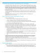
Priority is determined within the range of the number of initial copy operations performed at the same time. Therefore, until the first initial copy operations complying with the order of the Priority are completed, the additional initial copy operations are not started. Consistency group planning Consistency groups allow you to perform one operation on all pairs in the group. Consistency groups also ensure that all pairs are managed in a consistent status.
Figure notes: • RAID Manager manages the consistency group on all primary and secondary systems. Business Continuity Manager cannot be used with multiple systems. • Open and mainframe primary volumes (P-VOLs) receive I/O requests from their applications at the primary (main) site, and data in the volumes is updated. • Continuous Access Synchronous or Cnt Ac-S Z runs the copy operation in the consistency group.
group are resynchronized. Even if a Cnt Ac-S Z S-VOL is being accessed by a host, the pair is nevertheless resynchronized with the others. Make sure to check the status of all pairs in the consistency group before resynchronizing. • If you use BCM to delete a Cnt Ac-S Z pair in an open/mainframe consistency group with one primary and secondary system, only the Cnt Ac-S Z pairs are deleted. Use RAID Manager to delete the Cnt Ac-S pairs.
2. Perform the paircreate operation according to configuration definition file C created in Step 1. Procedure 3 To assign existing pairs to a new consistency group: 1. 2. 3. 4. 5. 6. Create RAID Manager configuration definition file A with which to use RAID Manager for pair operations. Perform the pairsplit operation according to configuration definition file A created in Step 1. Perform the pairresync operation on the Cnt Ac-S and Cnt Ac-S Z pairs, without designating a consistency group.
Split and suspension behaviors for pairs in a CG When the pairs in a consistency group receive updates while in the process of being split or suspended, or when they are about to be split or suspended, S-VOL data consistency is managed as follows: • If I/O processing is in progress on Cnt Ac-S or Cnt Ac-S Z pairs in the same consistency group, and the split or suspend operation begins, the I/O processing completes first, then the split/suspend operation is run.
- A split command is in progress. - I/O processing begins. In such a case, resynchronize the consistency group and then run the split command again. Host access after suspension You can specify settings for read/write access to the P-VOL and S-VOL in consistency groups after pairs are suspended. These settings are specified using RAID Manager or Business Continuity Manager. • The RAID Manager settings for Cnt Ac-S are optional. • The Business Continuity Manager settings for Cnt Ac-S Z are required.
This is shown in the following table indicates the following: • Italicized/Gray background: Cnt Ac-S and Cnt Ac-S Z pair status before the split operation on the consistency group • Regular font: Status after the split operation Pair statuses Cnt Ac-S Z pairs All Some = Duplex, All = Suspend some = Suspend All = PAIR Cnt Ac-S Cnt Ac-S pairs Cnt Ac-S: PSUS Cnt Ac-S: PSUS Cnt Ac-S: PSUS Cnt Ac-S Z: Suspend Cnt Ac-S Z: Suspend Cnt Ac-S Z: Suspend Some = PAIR, Cnt Ac-S: PSUS Cnt Ac-S: PSUS Cn
data is collected using performance monitoring software. Consult your HP account team for more information. Fibre Channel requirements The main and remote system must be connected using multi-mode or single-mode optical fibre cables. • For distances between .5 km to 1.5 km, one switch is required, but you can use a maximum of two switches. • For distances up to 1.5 km (4,920 feet), multimode shortwave Fibre Channel interface cables are used. • For distances from 1.5 km to 10 km, (4,920 feet to 6.
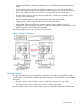
Set port topology to: Fab off, FC-AL. Switch connection The following figure shows a switch connection, in which up to three optical fibre cables are connected using switches. Two switches can be used. • • Set port topology to the following: ◦ NL port: Fab on, FC-AL ◦ N port: Fab on, Point-to-Point ◦ Some switch vendors require F port (for example, McData ED5000). Host I/O response time can be improved on long distance switch connections by using host mode options 49 and 50, or 51 and 65.
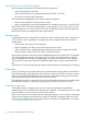
Figure 2 Extender Connection • Set port topology to the following: ◦ NL/FL port: Fab on, FC-AL ◦ F port: Fab on, Point-to-Point • Best practice is to create at least two independent data paths (one per cluster) between the main and remote system for hardware redundancy for this critical element. • When 4,000 pairs or more are used, we recommend that you restrict the number of pairs when creating pairs, so that 4,000 pairs or less use one physical path, to distribute load on the physical path.
4 Sharing Continuous Access Synchronous Z volumes This chapter helps you plan Cnt Ac-S Z pair volumes when they are shared with non-Cnt Ac-S Z volumes. All the software products that can be used with Cnt Ac-S Z are discussed here. Volume types that can be shared with Continuous Access Synchronous Z The following table shows when volumes used by other software can also be used as Cnt Ac-S Z P-VOLs and S-VOLs.
Functions and volumes Used as P-VOL? Used as S-VOL? P-VOL (main volume) in Pending status No No P-VOL in Duplex status Yes No. The volume can be used as an S-VOL only when you restore a Cnt Ac-S Z pair or perform a BCM YKRESYNC REVERSE operation. P-VOL in Suspend status Yes No. The volume can be used as S-VOL only when you restore a Cnt Ac-S Z pair or perform a BCM YKRESYNC REVERSE operation. P-VOL suspended due to a failure Yes No.
Functions and volumes Used as P-VOL? Used as S-VOL? For more information about Compatible FlashCopy, see the HP P9000 for Compatible FlashCopy Mirroring User Guide. The following topics clarify key information regarding shared volumes. Cache Residency Cache Residency volumes that can be assigned to Cnt Ac-S Z pairs, and Cache Residency operations can be performed on Cnt Ac-S Z P-VOLs and S-VOLs. For more information, see the HP XP P9000 Performance for Open and Mainframe Systems User Guide.
Provisioning Z automatically releases pages with reclaiming zero pages in the THP V-VOL, thus increasing usable capacity. Pages that include control cylinder information are not released (see next). ◦ If a pair does not include a THP V-VOL, volume capacity is counted toward Cnt Ac-S Z license capacity. If a pair includes a THP V-VOL, only the allocated page capacity of volume capacity is counted toward Cnt Ac-S Z license capacity.
Please note the following when sharing Cnt Ac-S Z volumes with BC Z volumes. • L1 and L2 BC Z pairs can be shared with Cnt Ac-S Z volumes. Both node and leaf S-VOLs are considered secondary volumes by Cnt Ac-S Z. • BC Z is recommended for in-system copy operations. However, if BC Z is not installed, Cnt Ac-S Z can be used to copy within the same P9500. This configuration requires at least one fibre cable loop. This cannot be done if the BC Z license key is installed in the P9500.
Configurations with Business Copy Z S-VOLs In the following figure, a BC Z S-VOL also functions as a Cnt Ac-S Z P-VOL. This configuration requires that the BC Z pair is split before the Cnt Ac-S Z pair is created. Figure 6 Shared BC Z P-VOL with Cnt Ac-S Z P-VOL Status reporting and data currency The following table shows the pair status that is reported for different combinations of shared volumes.
Continuous Access Journal Z Cnt Ac-S Z and Continuous Access Journal Z can share the same pair volumes. Using a combined Cnt Ac-S Z and Cnt Ac-J Z configuration can extend disaster recovery options to a third data center. Like Cnt Ac-S Z, a Cnt Ac-J Z pair maintains a copy of the production volume in a second location. However, unlike Cnt Ac-S Z, the Cnt Ac-J Z S-VOL is asynchronous, and the remote system can be located much greater distances from the local and remote Cnt Ac-S Z sites.
5 Configuration This chapter provides instructions for configuring Cnt Ac-S Z. Configuration workflow Configuration consists of the following tasks: • Check prerequisites for each procedure. • See “Planning pairs and pair volumes” (page 33). • On the main and remote system, install the data paths. See “Data path requirements and configurations” (page 46). • On main and remote system, configure the initiator and RCU target Fibre Channel ports that will be used for Cnt Ac-S Z operations.
3. In the RCU Operation window Display box, select Port. The ports associated with the local storage system are listed. 4. Right-click the port that you want to configure, and select the desired port type (Initiator, RCU Target, or Target). When you have modified all the ports you want, review the Preview list. 5. 6. • To change the attribute that you set for a port, right-click the port in the full upper list and select the new attribute.
• One of the fields in the procedure, Round Trip Time, is covered more extensively in “Determining Round Trip Time” (page 32). • Logical path settings are required in order to perform Cnt Ac-S Z pair operations and check pair status in Remote Web Console. Make sure to complete the procedure. If you cancel logical path settings, you will be unable to perform operations and check status. Also, operations involving logical paths cannot be performed when changing the microcode.
6. 7. 8. In the RCU S/N box, enter the remote RCU 5-digit serial number. In the Controller ID box, select the remote system’s controller ID. In the Logical Adr. (RCU CU) box, enter the CU number of the RCU being added. The CU number differs by the specified controller ID, as follows: • When the specified controller ID is 6 (XP P9500), or 5 (XP24000/XP20000 Disk Array), or 4 (XP12000 Disk Array or XP10000 Disk Array), you can select a CU number from 00 to FE.
12. In the Minimum Paths box, enter the minimum number of paths necessary for operations to continue. If the number of paths in Normal status falls below the Minimum Paths value you set, the main system suspends Cnt Ac-S Z pairs. This is done to prevent a performance drop on the host because of low overall bandwidth between main and remote system. The default is 1. • If your pairs contain critical data and you are using Cnt Ac-S Z for disaster recovery, set the minimum number to one.
NOTE: The default setting of 1 on the XP P9500 produces lower-than-expected initial copy throughput when the distances involved between the main and remote systems cause the RIO response time to exceed 15 milliseconds. • To determine the appropriate value for your system, see “Determining Round Trip Time” (page 32). • If using XP12000 Disk Array/XP10000 Disk Array, set the following parameters using the System Option window: Maximum Initial Copy Activity Path Blockade Watch 16. Click Set. 17.
6. In the MCU-RCU Path box, define the logical path between local and remote systems: In the MCU Port column, select a local system initiator port. In the RCU Port column, select the remote system RCU target port. This establishes a logical path with the selected initiator port. You can abbreviate the number to two characters. For example, “1A” can be entered instead of “CL1-A”. Letters may be uppercase or lowercase. 7. 8. 9. When you have entered the desired logical paths, click Set.
Changing options system-wide In this operation, you change concurrently copied volumes, path watch time, related SIMs (system-wide). Procedure 8 To change options system-wide: 1. In Remote Web Console, click Actions > Remote Copy > Continuous Access Synchronous for Mainframe > System Option. 2. 3. 4. Change to Modify mode by clicking the icon. In the tree, click Storage System Option. Right-click in the list area and select System Option from the menu. The related dialog box displays.
4. In the list, select and right-click the desired CU or CUs, then select CU Option from the menu. CU Option is disabled in the menu if Maximum Initial Copy Activities (CU) is disabled in the System Option dialog box. See previous procedure. The CU Option dialog box displays. 5. 6. In Services SIM of Remote Copy, select whether or not the services SIM in the remote CU is to be reported to the host. In PPRC support by host, select whether or not PPRC is to be supported by the host.
6 Pair operations This chapter provides instructions for performing Cnt Ac-S Z pair operations. Pair operations workflow Basic Cnt Ac-S Z operations consist of the following tasks. • Check prerequisites for each procedure. • Always check pair status. Each Cnt Ac-S Z operation requires the pair to be in a specific status. • Create a pair, in which the S-VOL becomes a duplicate of the P-VOL. • Suspend a pair, which separates the P-VOL and S-VOL and allows read/write access to the S-VOL if desired.
• Stop Performance Monitor before performing the initial copy to avoid overloading with TCP/IP traffic. • During this operation, you specify the fence level, which is a data protection option. For important information the options, see “Fence Level options for I/O to the P-VOL after suspension” (page 36) . Procedure 9 To create initial copies: 1. In Remote Web Console, click Actions > Remote Copy > Continuous Access Synchronous for Mainframe > Pair Operation. 2. 3.
The CESTPAIR TSO command does not support the option for scheduling order for the initial copy operation. When the Cnt Ac-S Z pair is created with CESTPAIR command, initial copy operation is performed according to the order that CESTPAIR is run. If a time-out error occurs during the Add Pair operation, the order specified in Priority may not run correctly. A time-out error may occur because of the CU configuration, or by a data path error.
the differential data to the main system, which merges all differential data to determine which tracks are out-of-sync. Prerequisite information • The pair must be in Pending or Duplex status. Procedure 10 To suspend one or more pairs: 1. In Remote Web Console, click Actions > Remote Copy > Continuous Access Synchronous for Mainframe > Pair Operation. 2. 3. 4. 5. 6. Change to Modify mode by clicking the icon. In the tree, select CU or the CU grouping where the pair is located.
5. If you are changing the P-VOL Fence Level, select a new fence level from the list. This is optional. • Data – The P-VOL is fenced if an update copy operation fails. • Status – The P-VOL is fenced only if the main system is not able to change S-VOL status to Suspended when an update copy operation fails. • Never – The P-VOL is never fenced. For more information, see “Fence Level options for I/O to the P-VOL after suspension” (page 36) . 6. 7. 8. 9.
4. 5. In the list, select the pair volume that you want to release, right-click, and then select Delete Pair from the menu. The Delete Pair dialog box displays. From the Deleting Mode list, select one of the following: • Normal: Deletes the pair or pairs only if the MCU can change the pair status of the P-VOL and S-VOL to Simplex. • All: Releases all Cnt Ac-S Z pairs with the same MCU and RCU (the same CU) as the selected pair. You can select this option from either the MCU or RCU.
7 Data migration This chapter discusses using Continuous Access Synchronous Z to migrate data from one storage system to another. Migration overview Continuous Access Synchronous Z can be used to move data from one system to another. Data is typically migrated for the following reasons: • To load data onto new or scratch volumes (for example, to a new or upgraded storage system). • To temporarily move data from an LDEV to accommodate other activities (for example, to make repairs).
If the original P-VOL is temporarily unavailable for update copy operations, suspend the new pair so that the new main system keeps track of changes. If you specify Only P-VOL for the CFW Data option, CFW data will not be migrated. Note that there is a possibility that I/O will terminate abnormally if you access the corresponding data set when you use S-VOL after migrating data.
8 Monitoring and maintenance This chapter provides information and instructions for monitoring and maintaining a Cnt Ac-S Z system. Monitoring pair status Monitoring the Cnt Ac-S Z system is an ongoing operation that should be performed frequently to keep track of and maintain your pairs. • When you want to perform a pair command, first check the pair’s status. Each operation requires a specific status or set of statuses. • Pair status changes when an operation is performed.
Pair status definitions Both Remote Web Console and Business Continuity Manager pair status names appear in the Pair Operation window Status column, except when the names are the same. When they are the same, the Business Continuity Manager (BCM) status does not appear. The following table shows both types of status names and their descriptions. In some cases, a particular status has no exact parallel status in the other interface. This is noted.
RWC status BCM status Description SUSPER (07), SUSPOP (0A) • In Suspended status, updates to the S-VOL stop. The storage system keeps track of updates to the P-VOL in order to update the S-VOL when the pair is resynchronized. P-VOL access S-VOL access Read/Write. Read Only if Mode=20 is ON, otherwise No. • When you suspend the pair from the remote system, that system changes the status of the S-VOL to Suspended. The main system detects this and changes P-VOL status to Suspended.
RAID Manager pair status names RAID Manager pair status names are different than Remote Web Console status names. The following shows the corresponding names. Remote Web Console pair status name RAID Manager pair status name Simplex SMPL Pending COPY Duplex PAIR Suspended (by operation) PSUS Suspended (by error) PSUE Suspended types This topic discusses pairs that are suspended by the user (Suspended-delete pair to RCU), and pairs that are suspended by the system (Suspended).
Suspend type RWC BCM PPRC by RCU SUSPCU(06) SUSPEND(06) Volume applies to Description P-VOL The main system detected an error condition at the remote system (RCU), that caused the main system to suspend the pair. The S-VOL suspend type is S-VOL Failure by MCU. S-VOL Delete pair to RCU SUSPER(07) SUSPEND(07) P-VOL The main system detected that the S-VOL status changed to Simplex because the user released the pair from the remote system.
For information on how to start and stop monitoring in Performance Monitor, see the HP XP P9000 Performance for Open and Mainframe Systems User Guide. To monitor copy operations, in the Remote Web Console, click Actions > Remote Copy > Continuous Access Synchronous for Mainframe > Usage Monitor. Descriptions of Usage Monitor fields are provided in the following table. Item Description Monitoring Switch • Enable: Monitoring is on. Graph displays. • Disable: Monitoring is off. Graph is disabled.
3. In the Display Item dialog box—Select Volume box, select one of the following: • ALL Volumes, to view I/O statistics for all LDEVs in the system. When selected, the LDKC number, CU number, and LDEV number appear above the graph. - A device ID ending in # (such as, 00:00:3F #) indicates the LDEV is an external volume. For more information, see the HP XP P9000 External Storage for Open and Mainframe Systems User Guide.
Monitoring, maintaining logical paths Check logical path status to keep track of and maintain paths. Procedure 15 To monitor logical path status: 1. 2. 3. In Remote Web Console, click Actions > Remote Copy > Continuous Access Synchronous for Mainframe > RCU Operation. Select MCU&RCU in the Display box. Select the RCU you want, right-click, then click RCU Status. The RCU Status dialog box displays. Logical path status definitions The following table provides logical path status descriptions.
2. 3. 4. 5. 6. Change to Modify mode by clicking the icon. In the RCU Operation window, click MCU&RCU. The tree and list on the right-side display information about remote system. In the tree, select the local system, and then select the desired remote system (RCU). Alternatively, select the RCU in the list, right click, and then click Edit SSID(s) & Path(s). All paths to the selected RCU are listed. Right-click the paths that you want to delete, and then click Delete Path.
Example of an exported text file The following shows an example of an exported text file.
4. 5. 6. 7. Select the P-VOL from the list pane, right click, and click Change Pair Option. The Change Pair Option dialog box displays. From the P-VOL Fence Level box, select the fence level for the pairs. From the CFW Data list, select whether the CFW data is copied to the S-VOL. • Copy to S-VOL: CFW data is copied to the secondary volume. • Only P-VOL: CFW data is not copied to the primary volume. Click Set then Apply.
7. Restart the pair using the Add Pair(Synchronous) dialog box (or CESTPAIR). Use Entire Volume for Initial Copy option to resynchronize the P-VOL and S-VOL. If you are absolutely sure that the P-VOL and S-VOL are still identical, you can restart the pair using the No Copy option.
3. 4. 5. In the Display box, click the MCU&RCU. In the tree, click the appropriate CU, then click the desired RCU. Alternatively, select the RCU in the list, right click, and then click Edit SSID(s) & Path(s). All SSIDs to the selected RCU are listed. To add a. In the list area, right-click the Path and then click Add SSID. b. In the Add SSID dialog box, type the new SSIDs and then click Set. 6. To delete: a. In the list area, right-click the SSID and then click Delete SSID. b.
General information Please review the following system behaviors regarding powering off: • Cnt Ac-S Z pairs are not affected when power is removed from a main system while operations are in progress. • When power is restored on the main system, the system communicates with the remote systems to confirm S-VOL pair status(es). Make sure that Cnt Ac-S Z communications are fully restored (all paths have normal status) before beginning I/O operations to the P-VOL.
3. 4. 5. Perform the planned outage of the remote systems as described in “Planned outage of the remote system or data path” (page 87). Power on the remote systems. Make sure that they are fully operational and ready to resynchronize operations before powering on the main system. Power on the main system, and make sure it is ready to resynchronize operations. If you suspend any pairs in step 2, you can also resynchronize (Resume Pair) those pairs now.
9 Troubleshooting This chapter provides Cnt Ac-S Z troubleshooting information. Error codes and messages Remote Web Console displays messages when error conditions occur during Cnt Ac-S Z operations. The message describes the error and provides a part code and error code. The error message may also include an XP P9500 error code. You may need to contact HP for assistance. See the HP XP P9000 Remote Web Console Messages guide for a list of the error codes.
Secondary path status problems The following table provides a list of secondary path status problems. Path status Description Corrective action Normal This path has been successfully established and can be used for Cnt Ac S Z copy activities. None required. Initialization Failed The link initialization • Make sure that the main and remote systems are physically procedure to the remote and correctly connected.
Path status Description system are being used for other connections. Corrective action systems, initiator ports for main systems. If necessary, connect to the remote system to delete paths. • Reconfigure the ports, then add the paths and RCUs to the MCU again. Serial Number Mismatch The remote system's S/N does not match the specified S/N. • Make sure that you entered the correct remote system S/N and Controller ID, and main and remote system port numbers.
Path status Description Corrective action The path relay equipment does not work. Repair the path relay equipment, then the path.* The connection cable is physically broken. Replace the broken cable, then restore the path.* Program Error A program error is detected. Restore the path.* This path was not established. Restore the path.* * To restore a path, delete and then add the path again. It may be necessary to delete and then add the RCU again.
Pair status/type Applies to Description Corrective action Suspended (pair P-VOL, suspended-error)/ S-VOL S-VOL Failure The main system detected an error • Check the path status on the RCU Status dialog during communication with the box. If errors occurred on the path, clear the remote system, or detected an I/O error conditions. error during update copy.
Error codes appear on the right of the equal symbol (=). Review RAID Manager error codes in the following topics. • “SSB2 error codes when SSB1 = 2E31/B901/B90A/B90B/B912/D004” (page 94) • “SSB2=B992 error codes when SSB1 = B901 or B90A” (page 102) SSB2 error codes when SSB1 = 2E31/B901/B90A/B90B/B912/D004 Error code Description (SSB2) 47A3 The pair cannot be suspended because of one of the following conditions: • Write access permitted in the S-VOL is unsupported. • The Swap Suspend is unsupported.
Error code Description (SSB2) B929 The pair operation was rejected because the online microcode is being replaced. B92A The pair cannot be created because the specified volume is a command device. B934 The pair cannot be created because Cnt Ac-S Z is not installed. B935 S-VOL hide mode is not supported. B93B The specified volume is a P-VOL. The pair cannot be released because the P-VOL is specified as an S-VOL. B941 The specified volume is an S-VOL.
Error code Description (SSB2) C199 A request for a Pairsplit-r operation was rejected because the corresponding volume or group was changing status. C1BE The pair’s status cannot be changed during the power-on processing of the DKC. C211 The command was rejected because the specified volume is a P-VOL.
Error code Description (SSB2) C297 The command was rejected because the specified volume is used as an S-VOL. C2A0 The pair cannot be created because the capacity that is used by software products other than Cnt Ac-S Z exceeds license capacity. C2A1 The command was rejected because an internal logical error has occurred. C2A3 The pair cannot be created because the used capacity exceeds the license capacity. C2B3 The command was rejected because THP V-VOL capacity is changing.
Error code Description (SSB2) C326 The storage system level cache is not valid in the RCU. C327 The pair cannot be created because the P-VOL is not available for remote copy. C328 The track formats of the P-VOL and the S-VOLdo not match. C32A The S-VOL is protected by the Volume Retention. C32B The P-VOL is protected by the Volume Retention. C32C The S-VOL is protected by the Volume Retention. C32D The S-VOL is protected by the Volume Retention.
Error code Description (SSB2) C378 The add pair operation is rejected because the number of active paths is less than the dedicated number of minimum paths. C379 There are fewer paths than the required minimum following a path failure or because an invalid path was specified. C37A An internal error occurred. C37B The S-VOL is not available. C37C The storage system level cache is not valid in the RCU. C37D The NVS is not ON in the RCU. C37E The S-VOL cache is unavailable.
Error code Description (SSB2) C3AD The remote system capacity exceeds the license capacity. C3AE Cnt Ac-S Z is not installed on the remote system. C3AF The DKC type of the remote system is not supported by Cnt Ac-S Z. C3B1 The number of paths is smaller than the required minimum number of paths. C3B3 An internal error occurred. C3B5 The configuration combination of P-VOL and S-VOL is invalid C3B6 The P-VOL is an BC Z volume. C3B7 The S-VOL is an BC Z volume.
Error code Description (SSB2) C3DB S-VOL pair status is not Suspended or Suspended. CB12 Cnt Ac-S, Cnt Ac-S Z, Cnt Ac-J, and Cnt Ac-J Z cannot be mixed in the consistency group. CB19 The remote system consistency group cannot be deleted because the Takeover command reversing operations between the P-VOL and S-VOL failed. CB1A The remote system consistency group was abnormally terminated because the Takeover command reversing operations between the P-VOL and S-VOL failed.
Error code Description (SSB2) CBDA The Add Pair operation cannot run because the used capacity of the Volume Retention on the remote system exceeds the license capacity. CBDC A request for an Add Pair operation was received in the Cnt Ac-S Z-Cnt Ac-J Z combination status. However, the command was rejected because the Mirror ID of Cnt Ac-J Z was 0.
For further information about the SIMs, see the HP XP P9000 Remote Web Console User Guide, or contact HP for assistance. TPC-R troubleshooting The following failure conditions and recovery solutions are provided for Basic HyperSwap function using TPC-R. Resynchronization fails due to shortage of host resources If a shortage of resources occurs in the host system, resynchronization of the Cnt Ac-S Z pair may fail with host system messages: IOSHM0803E (HyperSwap Disabled) and IOSHM0201I (Reason Code:40).
10 Disaster recovery This chapter discusses disaster recovery. Disaster recovery overview Preparing for disaster recovery involves the following major steps: 1. Identify the volumes and groups that contain important files and data for disaster recovery. 2.
You should prepare for file and database recovery using files for file recovery (for example, database log files that have been verified as current). You can also use the sense information with system time stamp that is transferred via ERC. CSUSPEND/QUIESCE TSO command See the IBM documents SG24 2595, SC35 0355, and SC35 0169 for important information about the optional QUIESCE parameter for the CSUSPEND TSO command.
10. At the remote or secondary site, start critical host operations, with the previous S-VOLs now the main volumes. Checking S-VOL currency with the P-VOL An S-VOL's currency refers to whether S-VOL data is identical to data in the P-VOL. This is dependent on your Fence Level setting, which determines whether data is copied to the P-VOL if an error occurs during an update to the S-VOL. The following table shows S-VOL currency information, based on pair status and the P-VOL fence level setting.
1. 2. At the local site, bring up the host servers. Make sure that Continuous Access Synchronous Z components are operational. At the local site, release all Continuous Access Synchronous Z pairs on the main system. Use the Deleting Mode All option to release all Continuous Access Synchronous Z pairs in each CU. Make sure to connect with all MCUs and all CUs to release all Continuous Access Synchronous Z pairs. 3. 4.
11 Support and other resources Contacting HP For worldwide technical support information, see the HP Support Center: http://www.hp.
Conventions for storage capacity values HP XP P9000 disk arrays use the following values to calculate physical storage capacity values (hard disk drives): • 1 KB (kilobyte) = 1,000 bytes • 1 MB (megabyte) = 1,0002 bytes • 1 GB (gigabyte) = 1,0003 bytes • 1 TB (terabyte) = 1,0004 bytes • 1 PB (petabyte) = 1,0005 bytes • 1 EB (exabyte) = 1,0006 bytes HP XP P9000 disk arrays use the following values to calculate logical storage capacity values (logical devices): • 1 KB (kilobyte) = 1,024 bytes •
CAUTION: IMPORTANT: NOTE: TIP: 110 Indicates that failure to follow directions could result in damage to equipment or data. Provides clarifying information or specific instructions. Provides additional information. Provides helpful hints and shortcuts.
A Pair operations using PPRC XP P9500 supports IBM Peer to Peer Remote Copy (PPRC) TSO and ICKDSF commands for performing Cnt Ac-S Z operations from the zSeries and S/390 host system. PPRC commands and requirements are described in this topic. However, not all instructions for using the commands are provided. Refer to the IBM user documentation for more information.
RWC operation PPRC Commands1 2 Issued to: Description 3 TSO ICKDSF Resume Pair CESTPAIR PPRCOPY (MODE=RESYNC) ESTPAIR P-VOL Resynchronizes a Cnt Ac-S Z pair, and sets the Cnt Ac-S Z initial copy options and pair options. Cnt Ac-S Z supports the optional MODE, PACE, and CRIT parameters. — P/DAS SWAP — MCU and RCU Supported by Cnt Ac-S Z. Redirects application I/Os from the P-VOL to the S-VOL. — CGROUP (FREEZE/ RUN) — MCU (P-VOL or simplex) Supported by Cnt Ac-S Z. Notes 1.
• When you issue the QUERY command with the PATH option to the S-VOL using ICKDSF, the command might be rejected. If this happens, you can check path status using the CQUERY command or Remote Web Console. • When using 2105 or 2107 CU emulation type for the MCU when the host is online to the S-VOL, running the CESTPAIR command to create a Cnt Ac-S Z pair requires ONLINSEC(YES). The operation fails if you do not use ONLINSEC or if you use ONLINSEC(NO).
Conventions used in TSO commands The following table shows typefaces and symbols used in PPRC TSO commands. Typeface or Symbol Description Example Normal text Used for command and keyword names or consoles. CESTPATH Italic text Used for parameters that are to be replaced by the appropriate ssid character or number string. Square bracket [ ] Used for keywords and parameters that can be abbreviated. [CGROUP(YES)] vertical dash Used to separate selectable keywords.
Parameter Description cc RCU port number (0x00-0xff) dd RCU CU number (0x00-0xfe) When WWNN is specified, CESTPATH parameters are the following. Parameter Description aabb MCU SAID (x’00 and port number) ccdd RCU SAID (x’00 and port number) WWN is the unique number for the controller and is indicated as follows.
However, if Cnt Ac-S Z pairs are registered in consistency groups, they are not placed in SCP status, even if the CGROUP (FREEZE) command is received. • ◦ Stops update copy operations to associated S-VOLs Logical paths are blocked between the specified MCU and RCU to stop Cnt Ac-S Z update copy operations to the S-VOLs. ◦ Suspends Cnt Ac-S Z pairs with P-VOLs on the specified MCU CU.
• SSIDs: The MCUs to which the CGROUP command will be issued must have consecutive SSIDs. The HP representative configures the SSIDs on the XP P9500 SVP. CAUTION: MVS requires that the storage system be offline during SSID changes. Reconfiguring SSIDs is therefore a disruptive event that must be carefully planned. Also, SCP time specified from Remote Web Console's CU Option dialog box is invalid for pairs created using a consistency group from Business Continuity Manager.
7. 8. I/Os are queued at the host. Host operations are switched to secondary site. Command sequence example You can issue CGROUP FREEZE/RUN commands manually or through automation (such as with GDPS). The following is an example sequence of actions you may implement. 1. Suspend host updates to all P-VOLs on the specified MCU. 2. Block the specified MCU-RCU path to stop update copy operations to S-VOLs.
The following figure shows example output when CQUERY is issued to the RCU that has a blocked path due to the CGROUP/FREEZE command. CQUERY - VOLUME The following figure provides example output when CQUERY is issued to an P-VOL that has been suspended by CGROUP/FREEZE. The output also shows the status of the FREEZE option: CGRPLB(YES) = enabled, CGRPLB(NO) = disabled. NOTE: The values for WWNN and LIC LEVEL in this figure and the next are invalid. Do not use the values.
IEA494I and IEA491E console messages When a pair is suspended, whether user-requested or caused by failure, the MCU generates sense information to notify the hosts. If the PPRC ERP PTF is installed and PPRC support by host = Yes is selected on the CU Option dialog box, this notification results in an IEA494I system console message and an IEA491E message. The IEA491E message indicates the reason for suspension.
If the host supports GDPS and the FREEZE option is enabled, the IEA494I system console message with extended long busy (which was generated in response to the SCI) triggers the CGROUP (FREEZE/RUN) command. XP P9500 response characteristics to failure conditions XP P9500 supports CGROUP in the GDPS environment by performing PPRC compatible actions and returning PPRC compatible messages according to failure conditions.
Failure condition One side of MCU cache blocked by SET CACHE OFF 5. Both sides of MCU cache blocked due to failure 6. Failure of a disk on the RCU Pairs suspended? Expected messages FREEZE function No3 No IEA480E, IEA491E, or IEA494I messages display. Not activated No No IEA480E, IEA491E, or IEA494I messages display. The MCU returns CC=3 for all I/Os.
Failure condition Pairs suspended? Expected messages 9. Failure of all links between the Yes MCU and RCU FREEZE function (1) IEA480 (SIM for Cnt Ac-S Z path blocked) message is reported when the next I/O to any device in this MCU is issued. (2) One or more IEA494I message showing EXTENDED LONG BUSY display. (3) One or more IEA491E or IEA494I message showing PAIR SUSPENDED display. 10. Power failure Activated if the FREEZE option is enabled for the affected MCU pairs. a.
Feature IBM 3990 6E XP P9500 XP24000/XP20000 Disk Array, XP12000 Disk Array/XP10000 Disk Array Interface between storage systems ESCON – max of 43 km communication using channel extenders Communication using switch and extender using Fibre Channel and Fibre Channel cable Communication using switch and extender using Fibre Channel and Fibre Channel cable Copy modes supported Synchronous Synchronous Synchronous, asynchronous The default for IBM software commands is synchronous.
Feature IBM 3990 6E XP P9500 XP24000/XP20000 Disk Array, XP12000 Disk Array/XP10000 Disk Array Minimum paths Not supported Default = 1. If the minimum number of MCU-RCU active paths falls below this value, all pairs will be suspended based on the Fence Level option in effect. Default = 1. If the minimum number of MCU-RCU active paths falls below this value, all pairs will be suspended based on the Fence Level option in effect.
B Continuous Access Synchronous Z scripting This appendix describes how to use script files to perform Cnt Ac-S Z operations. Scripting overview The Remote Web Console scripting function for Cnt Ac-S Z allows you to define multiple operations in a text file. You then run the script file which runs the operations, without having to issue the commands separately. With a script, you can set up and run a large number of commands within a short period of time.
The following table lists the internal macro commands for scripting. Type Macro Description For lists SetList Set (define) a list of items. AddList Add items to a list. Start Declares the beginning of a script. End Declares the end of a script. Delay Suspends script execution for the specified length of time. If Executes a script conditionally. EndIf Terminates a script conditionally. MakeString Makes strings; converts numeric value to character string.
The following table describes script components. Component Description Macro name Either an internal macro or a functional macro. Parameter list Parameter identification name (defined in each macro format) = non-list type expression. Expression List, constant, and work variable. List In a list description, a constant is enclosed in braces “{}”. A comma “,” is inserted between constants. For example {1, 2, 3, 4}, or {“ABC”, “qtw”}. Lists and work variables cannot be described in a list.
Symbol Use Unequal sign Used as an operator in the If statement when used alone. When the equal sign follows, nothing changes. Equal sign Used as a substitute sign when used alone. When the equal sign follows, it becomes an operator in the If statement. The before and after phrases are split by the symbols. Each symbol is recognized as a single word. Downloading a script for editing You can download script templates from Remote Web Console, then edit them to fit your systems and requirements. 1.
5. 6. 7. 8. 9. 10. 11. 12. In the Upload the script file dialog box, select the file that you want to transfer, and click Open. When the completion message appears, click OK. Repeat these steps to upload more script files. Click Close when finished. In the Script Operation window, select the file name from the Script File Name list. From the Operation list, select Run. To start the script, click Apply. When the confirmation message appears, click OK. Deleting script files 1. 2. 3. 4. 5. 6. 7.
000007 000001 08/03/05 10:06:22 0003 0000 Start HRC_CR19.SPT 000002 08/03/05 10:06:30 0015 0000 CreateHrcPair $Dev = _ilDevA, ... 000003 08/03/05 10:06:32 0015 0100 0x0200: 0x0201: 0x0202: 0x0203: 000004 08/03/05 10:06:39 0016 0000 CreateHrcPair $Dev = _ilDevA, ...
2. 3. 4. 5. 6. 7. Click Export in the Trace File box. When the confirmation message appears, click Yes. The Save the macro trace file dialog box appears. On the Save the macro trace file dialog box, enter the desired name and location for export the macro trace file. After the download is completed, the Save the error trace file dialog box appears. On the Save the error trace file dialog box, enter the desired name and location for export the error trace file.
The Details for the arguments are: • P-VOL device list (numeric): L x 0x10000 + C x 0x100 + VV, where L=LDKC#, C=CU#, VV=vol# within CU. • Serial number list (string): RCU serial number (serial number is five digits decimal 0-9). Do not specify more than 12 RCUs. • SSID number list (numeric): RCU SSID (four digits hexadecimal). • S-VOL device list (numeric): L x 0x10000 + C x 0x100 + VV, where L=LDKC#, C=CU#, VV=vol# within CU.
Parameter Value Priority _ilWorkA Fence level Never CFW flag 0 DFW flag 1 Time-Saving Mode [omit – default] Time stamp transfer Enable The following examples show the macro commands with the parameters listed in the preceding table. The example is shown in two parts.
• [,$DelRange= Release range list] • [,$TimeSave= Time-Saving Mode flag] The details for the arguments are: • Device list (numeric): L x 0x10000 + C x 0x100 + VV, where L=LDKC#, C=CU#, VV=vol# within the CU. When you write device list, you can omit LDKC# if the LDKC# is 0. For example, you can write 0x0102 when LDKC# is 0, CU# is 1, and vol# is 2. • Release mode list (numeric): 0 (0x00) = normal, 1 (0x01) = release by force; default = 0.
• Pending data flag list (string): To maintain interchangeability with the script made with the model before XP24000/XP20000 Disk Array, this parameter has been left. Do not use this parameter with XP P9500. • Time-Saving Mode flag: “Yes”: The Use Time-Saving Mode option is enabled. “No”: The Use Time-Saving Mode option is disabled. Default is “Yes”. This parameter is a non-list type and only one value can be specified.
• Time-Saving Mode flag: “Yes” = The Use Time-Saving Mode option is enabled; “No” = The Use Time-Saving Mode option is disabled; default = “Yes”. This parameter is a non-list type and only one value can be specified. • Time stamp transfer list (string): “Enable” = The host I/O time stamp is transferred from P-VOL to S-VOL; “Disable” = The host I/O time stamp is not transferred from P-VOL to S-VOL; default = current value. For the async pairs you must omit this parameter.
• Error level list (string): To maintain interchangeability with the script made with the model before XP24000/XP20000 Disk Array, this parameter has been left. Do not use this parameter with XP P9500. • Time-Saving Mode flag: “Yes” = The Use Time-Saving Mode option is enabled; “No” = The Use Time-Saving Mode option is disabled; default = “Yes”. This parameter is a non-list type and only one value can be specified.
Selecting devices The SelectHrcDevice command allows you to search for pairs whose status matches the specified parameters.
The following table shows SelectHrcDevice parameters and example values. Parameter Value Output list _ilDevA Device list _ilDevB RCU serial number _slWorkA RCU SSID _ilWorkA Fence level N Copy mode Synchronous0 Pair status Suspended Device attribute M The following example shows the SelectHrcDevice command using values in the preceding table.
Type Macro Description EndIf Terminates a script conditionally. MakeString Makes strings; converts numeric value to character string. Message The Message command is not yet supported. The Start and End commands are used together to begin and end the functions of a script. Every script must have a Start and End command. The If/EndIf commands are also used concurrently to string two or more functional commands together. The If/EndIf commands must be used together.
For example, to start a pair only if the pair was created successfully (result value of CreateHrcPair command is 0), use the IF/EndIf command, as shown in the following example. If (_Result==0) StartHrcPair EndIf The following table shows ASCII character codes. Character Code 0 0x30 1 0x31 9 0x39 A 0x41 Z 0x5a a 0x61 z 0x7a The following table shows the symbols for the allowed comparison expressions, and their meanings. Symbol Meaning == Expression 1 is equal to Expression 2.
MakeString $D=_sMsgB ,$Fmt=“EndCode=(0x%x):%s” ,$Item=_Result,_sMsgA The following shows an example of MakeString command output: _sMsgB = “EndCode=(0x110f):Error Occurred”. Message The Message command is not yet supported. SetList The SetList command allows you to assign specific items to a list. The format of the SetList command is: SetList $D= output list,$S=expression (attribute of the items to be assigned to the list with a numeric range of 0x0000 to 0xffff).
The work variable is part of an execution statement in a script. The following table describes work variable statements for list and non-list types. List type Variable Type Description and storage type _ilDEV Numeric Stores the device number list. Expression: _ilDevA, _ilDevB, _ilDevC _ilPriority Numeric Stores the priority number list. Expression: _ilPriorityA, _ilPriorityB, _ilPriorityC _ilWork Numeric Stores any 16-bit numeric values.
Variable Type Description 1 = OK, 6 = Yes, 7 = No. _SelectResult Numeric Stores the number of devices found by SelectHrcDevice macro. 0 = no devices found. Reserved status variables When a GetHrcStatus command is issued, the Remote Web Console computer obtains the status of the specified pairs from the XPP9500. The results of this query are displayed in the reserved status variables. The following table describes the valid reserved status variables.
The following table describes the syntax requirements that will be evaluated. Parameter Syntax requirements Length Check that each line does not exceed the maximum length for a script statement. Phrases in a script statement A phrase is enclosed by the quotation symbols. Use of the parentheses is correct, and the number of parentheses is exact. A statement does not terminate with an equal sign. The parameter identification name (phrase beginning with “$”) is always defined.
Parameter Syntax requirements EndIf The number of phrases matches. The macro is describe with the related If statement. MakeString Duplicate parameter identification names are not specified. The required parameter identification name is defined. The equal sign is described between the right side and one of $D, $Fmt and $Item. Specifying the right side is correct. The items are split by a comma (,) if multiple items are specified in $Item.
The following table describes scripting error messages. Message Conditions to verify Corrective action Syntax error The syntax validity of the script is checked at the Use the scripting error code to determine which start of execution. An error message will be line contains the syntax error. See the following displayed if failed. table and fix the syntax error. Parameter error The parameter validity of the script is checked when each instruction runs. An error message will be displayed if failed.
Message ID Internal code Error message Error description 2341 2f03-2f05, 4101, 4102 File I/O error (temporary). The work middle file is abnormal. The disk capacity maybe insufficient or the file may be corrupt. 2341 6101-6105 File I/O error (trace). The macro trace file cannot be opened. The disk capacity may be insufficient or the file may be corrupt. 2341 6111-6115 File I/O error (trace). The error trace file cannot be opened. The disk capacity may be insufficient or the file may be corrupt.
Message ID Internal code Error message 2359 28xx Value type mismatch. Line The type of the value assigned to the parameter in script = nnnn line nnnn is invalid. 2360 1001,4111,4112 Internal error. An internal program error has occurred. The program installation may not have been complete. 2361 4181 Mismatch script type. The script types specified by the Start macro and by the execution environment file are different. 2362 4182 Mismatch controller name.
Message ID Internal code Error message Error description 2362 5122 Parameter value error ($RcuSsid!=$Dev). A functional macro parameter error was found in the $RcuSsid!=$Dev settings. 2362 5123 Parameter value error ($Rdev!=$Dev). A functional macro parameter error was found in the $Rdev!=$Dev settings. 2362 5124 Parameter value error ($CopyMode!=$Sync). A functional macro parameter error is found in the $CopyMode!=$Sync settings. 2362 5132 Parameter value error ($CTG).
Message ID Internal code Error message Error description - 5001 API error (GetEquipInfoEx). An error occurred during the acquisition of the volume mounting status. - 5002 API error (GetPairStatus256). An error occurred during the getting pair status operation. ErrorCode=6005 xxxx * - - 5003 5004 API error (GetPairStatus). ErrorCode=6005 xxxx * An error occurred during the getting pair status operation. API error (SetCreatePair). An error occurred during the create pair operation.
C GUI reference This appendix describes the Remote Web Console windows, dialog boxes, fields, and behaviors for Continuous Access Synchronous Z (Cnt Ac-S Z). Pair Operation window Use this window to view Cnt Ac-S Z pairs.
Item Description Tree Displays the connected storage system, LDKC, CU grouping (grouping each 16 CUs), and the CUs that contain LVIs (CUs without LVIs are not displayed). Select the desired CU to display the LVIs for that CU. You can only select one CU at a time. Note: Though LDKC#01 displays in the Tree on some Cnt Ac-S Z windows, it is not available for use in this version. Preview List Lists and allows you to review your current operations not yet applied to the storage system.
Item Description • Suspend Pair. Used to suspend pairs. • Resume pairs. Used to resynchronize pairs that are suspended. • Change Pair Option. Used to change the pair options. Fields are described in the following rows. VOL LDKC number, CU number, and LDEV ID for this volume of the pair. The icons are: : Simplex : P-VOL : S-VOL Status RWC/BCM pair status. The BCM status name does not appear when it is the same as the RWC name. For descriptions, see “Pair status definitions” (page 75).
Item Description P-VOL and S-VOL areas The following displays in the order shown: • LDKC number, CU number, and device ID • Emulation type • Capacity (number of cylinders) CLPR Local volume’s cache logical partition number and name. Pair Status Status of the pair’s local volume. For descriptions of pair statuses, see “Pair status definitions” (page 75). Pair Synchronized The percentage of synchronization or consistency between the pair volumes.
Item Description Controller ID Controller ID and model name of the remote system. • For controller ID 6, XP P9500 is the model name. • For controller ID 5, XP24000/XP20000 Disk Array is the model name. • For controller ID 4, XP12000 Disk Array/XP10000 Disk Array is the model name. MCU-RCU Path Data path channel type. Copy Pace Number of tracks copied per interval during the initial copy. Copy pace can be 3 tracks or 15 tracks. This field displays only when the P-VOL is selected.
Item Description PM Status The status of the preserve mirror when it is associated with Compatible FlashCopy. If PAIR WAS THE TARGET OF A WITHDRAWN PM RELATIONS displays, the data of the pair volumes does not synchronize despite its pair status. Refresh the Pair Operation If the box is checked, the Pair Operation window updates when the Detailed Information window after this window dialog box closes. is closed: Add Pair(Synchronous) dialog box Use this dialog box to create a pair.
Item Description Priority Order for the current pair to be created among all pairs being created. Options are from 1 to 256. For the details of the scheduling order of the initial copy for which the Priority is set, refer to “Priority for initial copy operations and scheduling order” (page 38). Difference Management Method for managing differential data. Options are Auto, Cylinder, Track. CFW Data Options for whether CFW data is copied to the S-VOL.
See “Resynchronizing pairs” (page 69) for complete information. Item Description P-VOL Shows the selected volume’s LDKC number, CU number, LDEV number. P-VOL Fence Level Options for rejecting write operations to the P-VOL. Copy Pace Options for maximum number of tracks to be copied: 3 or 15. Priority Order for the current pair to be created among all pairs being created. Options are from 0 to 256. Time Stamp Options for whether the host I/O time stamp is transferred from P-VOL to S-VOL.
Item Description Volume Selected volume’s LDKC number, CU number, LDEV number. Deleting Mode Options for deleting the pair forcibly: Yes or No. Change Pair Option dialog box Use this dialog box to change the P-VOL Fence Level and CFW Data for an existing pair. See “Changing Fence Level, CFW Data” (page 83) for complete information. Item Description Volume Selected volume’s LDKC number, CU number, LDEV number. P-VOL Fence Level Options for rejecting write operations to the P-VOL.
Item Description Type Pair type: synchronous, synchronous-C, Multi-C, or all types P-VOL/S-VOL The type of pair volume to display, P-VOL or S-VOL, or all types MCU-RCU Path Path type (disabled at this time) CLPR Cache logical partition Internal/External VOL Whether the volume is internal or external Status Displays only volumes that have the selected RWC pair status: Simplex, Pending, Duplex, and/or Suspend.
• “Monitoring, maintaining logical paths” (page 81) • View the following: ◦ Information related to Cnt Ac-S Z storage systems in “RCU Operations list when “MCU&RCU” selected ” (page 164). ◦ Information related to ports in “RCU Operations list when “Port” selected ” (page 165). Item Description Tree The Display area allows you to select either MCU&RCU display (default) or Port. This affects Tree selections.
RCU Operations list when “MCU&RCU” selected List field-descriptions when MCU&RCU is selected in the Display box are shown below. The fields vary according to the selections you make in the tree: • “When LDKC, a CU group, or CU is selected in tree” (page 164) • “When an MCU or RCU is selected in tree” (page 165) When LDKC, a CU group, or CU is selected in tree The following columns display in the list area when MCU&RCU is selected in Display, and an LDKC, CU group, or CU is selected in the tree.
When an MCU or RCU is selected in tree The following columns display in the list area when MCU&RCU is selected in Display, and an MCU or an RCU is selected in the tree.
Item Description List Paths on this system. • No. The paths are listed in numbered order. • Path Status. The path’s condition. See “Logical path status definitions” (page 81) for definitions. • MCU Port. Port number of the MCU. • RCU Port. Port number of the RCU. RCU S/N Serial number of the RCU. The LDKC number is displayed in parentheses to the right of the RCU S/N. Controller ID Controller ID and model name. SSID SSIDs of the RCU. RCU CU No. CU number of the RCU. MCU-RCU Path Type of path.
Item Description Round Trip Time Time limit for data to travel from P-VOL to S-VOL. Check box, “Refresh the To refresh the RCU Operation window after closing the RCU Status dialog box, click the RCU Operation window check box. By default, the check box is not selected. after this dialog box is closed”: Add RCU (Fibre) dialog box Use this dialog box to link two storage systems for Cnt Ac-S Z pairs. See “Configuring storage systems, defining logical paths” (page 58) for complete information.
Item Description Minimum Paths Minimum number of paths for copy operations. RIO MIH Time (sec.) Time in which the copy operation must complete or the operation fails. Range is from 10 to 100 seconds. FREEZE Option Support for the CGROUP (FREEZE/ RUN) PPRC TSO command. Enable or Disable. Round Trip Time (ms) Time limit for data to travel from the P-VOL to the S-VOL. Add Path(Fibre) dialog box Use this dialog box to configure additional logical paths.
Item Description MCU-RCU Path Logical path between local and remote storage systems. MCU Port Local storage system initiator port. RCU Port Remote storage system initiator port. Add SSID dialog box Use this dialog box to add an SSID. See “Adding, deleting SSIDs for an RCU” (page 85) for complete information. Item Description SSID (1st) Existing SSID. SSID (2nd), (3rd), (4th) Additional SSIDs. Usage Monitor window Use this window to monitor and use copy-operations data and I/O statistics.
Item Description Monitoring Switch • Enable: Monitoring is on. Graph displays. • Disable: Monitoring is off. Graph is disabled. Gathering Interval Data collection interval. When monitoring is stopped, the default value (1) is displayed. Update Most recent data sample time on the graph. Usage Monitor Graph Remote I/O statistics and status of remote copy monitor. History window Use this window to view the history of operations performed on pairs, and the data associated with each operation.
Field Description Status • The current status of operation history: • No history file exists: Operation history does not exist. • Reading a history file failed: An attempt to read operation history failed. • Updating ... n (%): Updating of operation history is now in progress, where “n (%)” indicates the progress (in %). • Complete: Updating of operation history has completed. Last Update Time Date and time when operation history was last updated.
Related Topics “Export operations history” (page 172) History window notes • The operation rows may not appear in chronological descending order. To sort the information in descending (or ascending) order, click a heading. • The history file always contains the most recent operations up to a maximum of 524,288 operations. Information older than seven days is not shown.
Field Description Tree Provides access to the storage system. Option table Right-clicking a row displays a context menu with the System Option command, which is used to change the storage system options. Clear SIM When clicked, clears all remote copy SIMs (service information messages) from the connected storage system. Activities The system option. See “Setting number of VOLs.
Item Description Services SIM of Remote Copy Options for whether the Services SIM in the CU is reported to the host. PPRC support by host Options for PPRC support for the host. SCP Time (sec.) State change pending (SCP) time. The time ranges from 0 to 518400 seconds. Maximum Initial Copy Activities Number of volumes that can be copied concurrently during an initial copy operation. The number ranges from 1 to 16 volumes.
Glossary This glossary defines the special terms used in this document. Click the letter links below to navigate. 2DC two-data-center. Refers to the local and remote or secondary sites, or data centers, in which Cnt Ac-S Z (Cnt Ac-S Z) and Continuous Access Journal Z (Cnt Ac-J Z) combine to form a remote replication configuration.
CG See consistency group (CTG). CH channel channel adapter (CHA) The hardware component that processes channel commands from hosts and manages host access to cache. channel path The communication path between a channel and a control unit. A channel path consists of the physical channel path and the logical path.
updated. The original snapshot of the volume is maintained by storing the to-be-changed data blocks in the data pool. DB database DBMS database management system delta resync A disaster recovery solution in which Cnt Ac-S and Continuous Access Journal systems are configured to provide a quick recovery using only differential data stored at an intermediate site. device A physical or logical unit with a specific function. device emulation Indicates the type of logical volume.
external application A software module that is used by a storage system but runs on a separate platform. external port A fibre-channel port that is configured to be connected to an external storage system for External Storage operations. external volume A logical volume whose data resides on drives that are physically located outside the HP storage system.
initiator port A fibre-channel port configured to send remote I/Os to an RCU target port on another storage system. See also RCU target port and target port. intermediate site (I-site) A site that functions as both a Cnt Ac-S secondary site and a Continuous Access Journal primary site in a 3-data-center (3DC) cascading configuration. internal volume A logical volume whose data resides on drives that are physically located within the storage system. See also external volume.
logical unit (LU) path The path between an open-systems host and a logical unit. logical volume See volume. logical volume image (LVI) A logical volume that is configured for use by mainframe hosts (for example, 3390-9). LU logical unit LUN logical unit number LV logical volume M-JNL main journal M-VOL main or primary volume main control unit (MCU) A storage system at a primary or main site that contains primary volumes of Cnt Ac-S Z remote replication pairs.
OS/390 Operating System/390 P-site primary site P-VOL See primary volume. pair Two logical volumes in a replication relationship in which one volume contains original data to be copied and the other volume contains the copy of the original data. The copy operations can be synchronous or asynchronous, and the pair volumes can be located in the same storage system (in-system replication) or in different storage systems (remote replication). pair status Indicates the condition of a copy pair.
RAID group A redundant array of inexpensive drives (RAID) that have the same capacity and are treated as one group for data storage and recovery. A RAID group contains both user data and parity information, which allows the user data to be accessed in the event that one or more of the drives within the RAID group are not available. The RAID level of a RAID group determines the number of data drives and parity drives and how the data is “striped” across the drives.
SAN storage-area network SATA serial Advanced Technology Attachment SC storage control SCDS source control dataset SCI state change interrupt scripting The use of command line scripts, or spreadsheets downloaded by Configuration File Loader, to automate storage management operations. SCSI small computer system interface secondary site The physical location of the storage system that contains the primary volumes of remote replication pairs at the main or primary site.
system option mode (SOM) Additional operational parameters for the RAID storage systems that enable the storage system to be tailored to unique customer operating requirements. SOMs are set on the service processor. V version; variable length and de-blocking (mainframe record format) V-VOL virtual volume V-VOL management area Contains the pool management block and pool association information for Snapshot operations.
Index A Add Pair dialog box, 158 Add Path dialog box, 168 Add RCU dialog box, 167 Add SSID dialog box, 169 additional shared memory, 28 B bandwidth, 46 Basic HyperSwap, 24 bitmap areas, 38 Business Continuity Manager about, 11 command device for, 16 commands compared with PPRC, 18 specifications for, 15 C cache memory changes, and pair status, 28, 76 cache requirement, 28 cache, planning considerations, 28 CESTPATH command, 114 CESTPATH/YKBLDPTH, SAID values for, 19 CGROUP (FREEZE/RUN) support, 115 CGROUP
M non-volatile storage (NVS), planning considerations, 28 RCU Status dialog box, 165 RCU, MCU, 9 related documentation, 108 remote path, description, 10 Resume Pair dialog box, 159 resynchronizing pairs, 69 RMF, 22 round trip time, changing, 85 O S overview, 8 S-VOL Read option, 29 S-VOL, planning I/O for, 35 SAID values, 19 scheduling order for initial copies, 63 script errors, 148 scripts, 126 shared memory changes, and pair status, 28, 76 sharing volumes, 50 SIMs, 102 SSIDs, adding and deleting, 85
V Virtual LVI/LUN, sharing volumes with, 56 VOLSERS, handling duplicate, 35 volumes, sharing with others, 50 W wait time, changing, 85 web sites HP subscription service, 108 websites HP , 108 product manuals, 108 187