HP XP P9000 Continuous Access Journal User Guide Abstract This guide explains how to use HP XP P9000 Continuous Access Journal Software to replicate data between local and remote HP XP P9000 disk arrays and to achieve disaster tolerance with maximum application performance. Topics include setting up remote copy connections, configuring the storage system, creating and monitoring remote copies, recovering from a disaster, and troubleshooting.
© Copyright 2010, 2014 Hewlett-Packard Development Company, L.P. Confidential computer software. Valid license from HP required for possession, use or copying. Consistent with FAR 12.211 and 12.212, Commercial Computer Software, Computer Software Documentation, and Technical Data for Commercial Items are licensed to the U.S. Government under vendor's standard commercial license. The information contained herein is subject to change without notice.
Contents 1 Continuous Access Journal overview ............................................................8 Continuous Access Journal software ...........................................................................................8 How Continuous Access Journal works........................................................................................8 Hardware and software components...........................................................................................9 P9500 storage systems.....
Sizing bandwidth ..................................................................................................................34 Five sizing strategies ..........................................................................................................34 Calculating bandwidth ......................................................................................................35 Sizing bandwidth for peak write-workload........................................................................
Logical path maintenance........................................................................................................86 Modifying data-transfer time threshold .................................................................................86 Deleting logical paths ........................................................................................................87 Deleting the Cnt Ac-J relationship ........................................................................................
A 3 Cnt Ac-J data-center configurations........................................................126 Overview............................................................................................................................126 3 Cnt Ac-J DC cascade configuration......................................................................................126 Failure recovery...............................................................................................................
Journal Detail window ..........................................................................................................159 Change Journal Option dialog box ........................................................................................161 Change Mirror Option dialog box .........................................................................................162 Edit Journal Volumes dialog box.............................................................................................
1 Continuous Access Journal overview With Continuous Access Journal (Cnt Ac-J), you create and maintain a remote copy of a data volume on a P9500 storage system. This guide provides instructions for planning, configuring, operating, maintaining, and troubleshooting a Continuous Access Journal system. Continuous Access Journal software With Continuous Access Journal, you copy application data to a secondary P9500 system at a remote location.
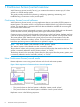
1. 2. 3. Journal obtain - When the host sends an update to the primary volume (P-VOL), the primary (local) system’s journal-obtain function triggers a copy of the updated data to the master journal volume. • The host assigns write-sequence numbers to the data sent to the master journal volume. • Write-sequence numbers and other metadata attached to journal data ensure consistency with the data in the P-VOL. Journal copy - Data is copied from the master journal to the restore journal.
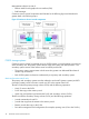
Management software consists of: • Remote Web Console graphical user interface (GUI) • RAID Manager Continuous Access Journal components are illustrated in the following figure and described in greater detail in the following topics. Figure 2 Continuous Access Journal components P9500 storage systems Continuous Access Journal is operated using two P9500 systems, one at the primary site and one at the secondary site. The primary system consists of the main control unit (MCU) and the .
Pair volumes Original data is stored in the P-VOL and the remote copy is stored in the S-VOL. The pair can be paired, split, re-synchronized, and returned to the unpaired (called “simplex”) state. When synchronized, the volumes are paired; when split, new or changed data sent to the P-VOL is not copied to the S-VOL. When re-synchronized, changed data is copied to the S-VOL. If a disaster occurs, production operations can be transferred to the S-VOL.
Data path The physical transmission link between the local and remote systems is called the data path. Continuous Access Journal commands and data are transmitted through the fibre-channel data path and switches. The data path is connected to the primary and secondary systems through two types of fibre-channel ports, Initiator and RCU Target ports. Continuous Access Journal requires paths in both directions.
Update copy operation When a host has new or changed information, the following occurs in the primary system: • The update is written to the P-VOL • The update is copied to the master journal along with metadata that includes sequence and other consistency information. The remote system issues the read-journal command (independent of host I/O activity). At this time, the following occurs: ◦ Any data in the master journal is sent to the restore journal. ◦ The updated data is copied to the S-VOL.
resynchronized, the primary system merges the P-VOL and S-VOL bitmaps, and the differential data is copied to the S-VOL. The number of bitmap areas affects the maximum possible number of pairs that can be created in the system. S-VOL write option When splitting a pair, you can set an option allowing write I/O to the S-VOL.
2 Requirements and specifications This chapter provides system requirements for Continuous Access Journal. System requirements Continuous Access Journal operations are performed from the primary system to the secondary system, which contain the Cnt Ac-J P-VOLs, S-VOLs, and master and restore journal volumes. Copy operations are carried out via the data path. General requirements for these and all Cnt Ac-J components are listed below.
Table 1 General system requirements (continued) Item Requirement When both systems are P9500, you can use multiple path groups. This is done by registering path groups with multiple path group IDs in the same storage system. But note that only one path group can be specified for a mirror. Up to eight paths can be registered in one path group. Path group Groups of logical paths, which allows you to configure or change the configuration of multiple paths at the same time.
Table 1 General system requirements (continued) Item Requirement cache capacity by 25 percent for Cnt Ac-J. Also, 1 GB should be added for each journal on the system. Note: When pair status is COPY, neither cache nor shared memory can be added to or removed from the system. When either of these tasks is to be performed, first split any pairs in COPY, status, then resynchronize when the cache or shared memory operation is completed. Host failover software Required for disaster recovery.
3 Planning volumes, P9500 systems This chapter provides information and instructions for planning Continuous Access Journal volumes, P9500 systems, and other important requirements and restrictions. Plan and design workflow Planning the Continuous Access Journal system is tied to your organization’s business requirements and production system workload. This means defining business requirements for disaster downtime and measuring the amount of changed data your storage system produces over time.
To ensure that journals can hold the amount of data that could accumulate, they must be sized according to the following: • The maximum amount of time that journals could accumulate data. You develop this information by determining your operation’s recovery point objective (RPO). • The amount of changed data that your application generates. This is done by measuring write-workload.
1. 2. Using your performance monitoring software, collect the following: • Disk-write bytes-per-second (MB/s) for every physical volume that will be replicated. • Data should be collected over a 3 or 4-week period to cover a normal, full business cycle. • Data should be collected at 5 minute intervals. If you use averages, shorter intervals provide more accuracy. At the end of the collection period, convert the data to MB/second, if needed, and import into a spreadsheet tool.
• All the P-VOLs, or S-VOLs, in a journal must belong to the same storage system. • Journal numbers of master and restore journals that are paired can be different. If using a consistency group number, the consistency group number of the P-VOL and S-VOL must be the same. • Each pair relationship in a journal is called a "mirror". Each pair is assigned a mirror ID. The maximum number of mirror IDs is 4 (0 to 3) per system.
Please see “Planning ports for data transfer ” (page 39) for a full discussion on the type and number of fibre-channel ports required for your system. Planning journal volumes In addition to sizing journal volumes, you should be aware of the following requirements and restrictions. • Journal volumes must be registered in a journal before the initial pair-copy operation is performed. • Journal volumes must be registered on both the local and remote systems.
example, when the P-VOL is a LUSE volume in which 1-GB, 2-GB, and 3-GB volumes are combined in this order, the S-VOL must be a LUSE volume in which 1-GB, 2-GB, and 3-GB volumes are combined in this order. In addition, RAID1, RAID5, and RAID6 can coexist in the LUSE volume. • Cnt Ac-J supports the Virtual LUN feature, which allows you to configure custom LUs that are smaller than standard LUs. When custom LUs are assigned to a Cnt Ac-J pair, the S-VOL must have the same capacity as the P-VOL.
NOTE: Doing this calculation for multiple volumes can result in inaccuracies. Perform the calculation for each volume seperately, then total the bitmap areas. The following examples show correct and incorrect calculations.
When you create more pairs than the maximum initial copy setting, the pairs with priorities within the maximum number specified run concurrently, while the pairs with priorities higher than the maximum number wait. When one pair completes, a waiting pair begins, and so on.
Sharing volumes with other P9500 software volumes Continuous Access Journal volumes can be shared with other product volumes. Sharing pair volumes enhances replication solutions, for example, when Continuous Access Journal and Continuous Access Synchronous or Business Copy volumes are shared.
S-VOLs in chronological order (older data are restored earlier). This ensures that the update sequence is maintained. Note the following when planning for multiple systems: • Remote Web Console is required at the primary and secondary sites. • RAID Manager is required on the host at the primary and secondary sites. • Journal data is updated in the secondary system based on the time stamp issued from RAID Manager and the sequence number issued by the host with write requests to the primary system.
registered in a RAID Manager consistency group. The following figures show different configurations in which multiple journals are registered in a single RAID Manager consistency group.
3DC configurations using 3 Cnt Ac-J sites With Continuous Access Journal, you normally use two data centers—the primary and secondary sites. You can employ a third site to create a 3-data-center (3DC) configuration. Using three sites makes a third copy of production data available in the event of primary and secondary site failure. You can set up three Cnt Ac-J sites in multi-target or cascade configurations. You also have the option of adding a delta resync pair.
Figure 4 Remote path between LDKC00 of P9500 and XP24000/XP20000 Disk Array • When connecting P9500 with XP12000 Disk Array or XP24000/XP20000 Disk Array, contact your HP representative for information regarding supported microcode versions. • When connecting P9500 with XP12000 Disk Array, set up the P9500 using a CU:LDEV number between 00:00 to 3F:FF, but do not use 40:00 or higher.
• Install the Cnt Ac-J remote copy connections (cables, switches, and so on) between the primary and secondary systems. • When setting up data paths, distribute them between different storage clusters and switches to provide maximum flexibility and availability. The remote paths between the primary and secondary systems must be separate from the remote paths between the host and secondary system.
Table 2 System option modes (continued) Mode Description • Delete the Cnt Ac-S pair. • Resynchronize the Cnt Ac-J pair. Mode 474 ON: Using RAID Manager improves performance. Mode 474 OFF: Operations run normally. If the P-VOL and S-VOL are both THP V-VOLs, initial copy performance might not improve with SOM 474 set to ON. This is because with THP V-VOLs, not all areas in a volume are allocated for Cnt Ac-J; therefore not all areas in the P-VOL are copied to the S-VOL.
Table 2 System option modes (continued) Mode Description Mode 908 ON: Difference in CM allocation capacity among MPBs with different workloads is large. Mode 908 OFF (default): Difference in CM allocation capacity among MPBs with different workloads is small. Notes: 1. Apply this SOM to CLPRs used only for Cnt Ac-J JNLGs. 2. Since CM capacity allocated to MPBs with low workload is small, the performance is affected by a sudden increase in workload. 3. This SOM is effective for a CLPR.
4 Planning the data path A data path must be designed to manage your organization’s throughput to the remote site. The bandwidth, number of ports, and fibre-channel data path configuration that you use help ensure that your update data arrives at the remote site in a time consistent with your organization’s RPO. This chapter provides instructions for calculating bandwidth and designing the data path network.
the journals will be completely emptied to the S-VOL only occasionally. If bandwidth is sized below average write-workload, the journals never fully drain and eventually overflow. • You can size bandwidth and journal size for long-haul data migration, to be used where data consistency is not required. In this strategy, you alternate pair status between resync and suspend in order to “batch copy” point-in-time copies. When pairs are suspended, journals are not used to queue write operations.
3. 36 With a base bandwidth value established, make adjustments for growth and a safety factor. • Projected growth rate accounts for the increase expected in write-workload over a 1, 2, or 3 year period. • A safety factor adds extra bandwidth for unusually high spikes that did not occur during write-workload measurement but could.
Sizing bandwidth for peak rolling average write-workload Sizing bandwidth 37
1. Using write-workload data imported into a spreadsheet and your RPO, calculate write rolling-averages. For example, if RPO time is 1 hour, then 60-minute rolling averages are calculated. Do this by arranging the values in six 10-minute intervals, as follows: 1. In cell E4 type, =average(b2:b7), and press Enter. (Most spreadsheet tools have an average function.) This instructs the tool to calculate the average value in cells B2 through B7 (six 10-minute intervals) and populate cell E4 with that data.
2. 3. From the spreadsheet or graph, locate the largest or highest rolling average value. This is the peak rolling average, which indicates the base amount of data that your bandwidth must be able to handle. With a base bandwidth value established, make adjustments for growth and a safety factor. • Projected growth rate accounts for the increase expected in write-workload over a 1, 2, or 3 year period.
The secondary system initiator port sends journal query commands to the primary RCU target port. The data is then sent through these ports — that is, from primary side RCU target ports to secondary system initiator ports. Note the following: • An initiator port on one side must have an RCU target port on the other side. • Two or more initiator ports must be configured before you can create the Cnt Ac-J relationship with the secondary system and create pairs.
Determining required number of ports The data transfer speed of your Cnt Ac-J ports must be greater than peak write-IOPS. This means that you must dedicate the number of ports to a Cnt Ac-J pair that will be able to handle the peak IOPS generated by your production system. The minimum number of ports for a Cnt Ac-J system is two. To determine the required number of initiator and RCU target ports 1. Measure the write workload you want to replicate on your production system.
Figure 8 Data path types, switches, and distances Supported data path configurations The remote data path can be configured using one of the following connection types. For a switch connection, you must set the port to Fabric on, Point-to-Point (F-port). • Direct connection, as shown in Figure 9 (page 42). Direct connection (loop only) is a direct link between the local and remote arrays. NL-port (Node Loop) connections are supported for the data path and host-to-system path.
Figure 10 Switch connection configuration Figure 11 Extender connection configuration NOTE: When an MCU and RCU are connected using switches with a channel extender, and multiple data paths are configured, the capacity of data to be transmitted may concentrate on particular switches, depending on the configuration and the settings of switch routing. Contact your HP account team for more information.
5 Configuration operations This chapter provides instructions for configuring Continuous Access Journal. Configuration workflow This workflow and subsequent topics guides you in setting up the primary and secondary systems for Continuous Access Journal operations using Remote Web Console. 1. Log in to Remote Web Console. 2. Define the fibre-channel port attributes. See “Defining fibre-channel port attributes ” (page 44), below. 3. Set up logical paths between the primary and secondary systems.
2. 3. Click to change the mode from View to Modify. In the Display box, select Port. 4. In the list of ports, right-click the port that you want to change and select the desired port type: Initiator, RCU Target, or Target). When you are finished defining ports, review the Preview list. 5. 6. • To change a setting, right-click the port in and select the attribute. • To delete a setting, right-click the port and select Delete. Click Apply to save your modifications in the system.
• The system's serial number, LDKC number, controller ID, Path Gr. ID, and port number will be required during this procedure. • Logical path settings are required in order to perform Continuous Access Journal pair operations and check pair status in Remote Web Console. Make sure to complete the procedure. If you cancel logical path settings, you will be unable to perform operations and check status. Also, operations involving logical paths cannot be performed when changing the microcode.
5. 6. 7. 8. In the S/N box, enter the remote system’s 5-digit serial number. In the LDKC box, select the remote system’s LDKC number. Currently, all system models’ LDKC is 00 In the Controller ID box, select the remote system’s controller ID. • For P9500, the controller ID is 6. • For XP24000/XP20000 Disk Array, the controller ID is 5. • For XP12000 Disk Array/XP10000 Disk Array, the controller ID is 4. In the Path Gr.
11. In the DKC Option dialog box, Minimum Paths is intended for a future release. Continue to the next step. 12. In the RIO MIH Time box, enter the time interval in seconds that, if exceeded, will cause the data transfer operation to be reported as failed by the system. Valid values range from 10 seconds to 100 seconds, and the default is 15 seconds. RIO MIH means “remote I/O missing interrupt handler”. NOTE: The recommended RIO MIH setting for a 3DC cascade configuration is 20 seconds. 13. Click Set.
1. 2. In the Port column, select a local system initiator port. In the Pair-Port column, select the remote system RCU target port. You may enter port numbers using the keyboard. You may abbreviate the number into two characters. For example, “1A” may be entered instead of “CL1-A”. Letters may be uppercase or lowercase. 6. 7. 8. Make any changes in the Add Path dialog box, then click Set. Review the logical paths in the Preview list.
4. In the Maximum Initial Copy Activities box, enter the number of volumes that you want to be copied concurrently during initial copy and resynchronization operations. Valid values range from 1 to 128 volumes. The default is 64 volumes. • This setting can impact performance on the primary system, depending on the number specified and the amount of I/O activity. By using the default, 64 volumes, you limit the impact of initial copy operations on system performance.
Procedure 5 To register journal volumes 1. In Remote Web Console, select Actions > Remote Copy > Continuous Access Journal > Journal Operation. 2. 3. In the Journal Operation window, click to change the mode from View to Modify. To register journal volumes in an existing journal, select the journal from the Registered > LDKC00 tree. To register journal volumes in a new journal, select the journal from the Free > LDKC00 tree. The selected journal displays in the table pane. 4.
5. In the Edit Journal Volumes dialog box, in the Free Volumes list, select the volumes that you want to register. Each row represents a volume in the list. NOTE: Only OPEN-V volumes display in Free Volume, If you cannot find the volumes, select one of the following in the PG/CU change area: • PG, then enter a parity group number in the box, and click Show. A list of volumes in the specified parity group displays. Select the volumes that you want to register. • PG(Ext.
8. 9. Review the added journal volumes in the Preview list. • To add another volume, right-click the desired journal and select Modify. In the dialog, add the volume and click Set. • To cancel a path, right-click it in the Preview list and select Cancel. Click Apply to save the configuration. After journal volumes are registered to the unused journal, the journals are shown below as Registered >LDKC00 in the tree. If an error occurs, right-click the item in the Preview list and select Error Detail.
6 Pair operations This chapter provides instructions for performing Continuous Access Journal pair operations. Pair operations workflow The basic Cnt Ac-J operations consist of the following: • Check pair status. Each Cnt Ac-J operation requires the pair to be in a specific status. • Create the pair, in which the S-VOL becomes a duplicate of the P-VOL. • Split the pair, which separates the P-VOL and S-VOL and allows read/write access to the S-VOL if desired.
• If you are creating a Cnt Ac-J pair for delta resync, see “Procedure for creating a delta resync pair ” (page 146). • Make sure Performance Monitor is stopped. The following additional information may be useful to you before beginning the procedure: • You will select the volumes you will pair by the volume’s port, GID, and LUN. Make sure to have this information available. • You will assign master and restore journals to the P-VOL and S-VOL during the operation.
5. • Data for the selected volume displays in the P-VOL box. The numbers indicate the volume port, GID, LUN, and volume • One P-VOL displays at a time, even if you selected multiple volumes for pairing. The volume with the lowest number displays first. Specify an S-VOL. • To create one pair, select the port, GID, and LUN from the three S-VOL boxes. If you selected multiple volumes as P-VOLs, the S-VOL you specify is paired with the P-VOL displayed in P-VOL.
2. 3. Select a mirror ID (0 to 3) from the Mirror ID list. Select a restore journal from the R-JNL list. Only journal numbers between 000 and 0FF display. NOTE: Z. 7. 8. The M-JNL list does not display journal numbers used by Continuous Access Journal From the CT Group list, specify the consistency group number. If possible, assign the consistency group number matching the Continuous Access Journal journal number (best practice).
15. In the Pair Operation window, verify that the pair status is correct based on the initial copy option: Initial Copy Option Current Pair Status Should Be Entire or None COPY or PAIR Delta HOLD, Holding 16. (Optional) You can monitor the progress of the paircreate operation by clicking File > Refresh in the menu bar. This updates the information in the list. You can also review current pair activity and pair status in the Detailed Information dialog box.
5. 6. In the Pairsplit-r dialog box’s S-VOL Write list, select one of the following: • Enable, to permit hosts to write data to the S-VOL.) • Disable, (the default) to prevent hosts from writing to the S-VOL From the Range list, select one of the following: • LU, to split only the selected pairs. • Mirror, to split all pairs in the same selected pair’s mirror. If you are splitting some pairs in a mirror but not all, you must select LU for each of these pairs.
4. 5. 6. Select one or more mirrors. Right-click and select Mirror >Pairsplit-r from the menu. In the Pairsplit-r dialog box, follow the steps for the each option in “Splitting pairs ” (page 58). Note that Mirror in the Range field cannot be changed for this operation. You can verify the Stopped status of the mirror when the mirror split operation is completed. Creating point-in-time copies Continuous Access Journal allows you to make Point-in-Time (PiT) copies of volumes in the same journal.
3. 4. 5. In the tree, select the port or host group for the pair. In the list of associated pair volumes in the right pane, select one or more pairs according to the following: • Select pairs for resynchronization in PSUS or PSUE status. • Select pairs for the delta resync operation in HOLD or HOLDING status. • Select a pair in HLDE status to change the status to HOLD. In the Pairresync dialog box Range list, select one of the following: • LU, to resync only the selected pair.
Resynchronizing mirrors When you resynchronize a mirror, all the pairs with the mirror ID are re-synchronized. Use this procedure also to perform the delta resync operation on all pairs in a mirror or to change pair status of all pairs in the mirror from Hold(Failure) to Hold. Prerequisite information This operation must be performed from the primary system only.
• If the operation fails, the P-VOL nevertheless becomes SMPL. Transfer of differential data to S-VOL is terminated. • If you plan to delete all pairs in the journal and then create another pair, be sure to wait at least one minute after deleting the pairs before creating the new pair. • Perform pair deletion when write I/O load is low to reduce impact on performance. Operations on pairs with different status in the same mirror may result in suspension during periods of heavy write I/O.
If you select Force when Range is set to LU, the other pairs in the same journal are also suspended. CAUTION: 7. 8. 9. Please note the following: ◦ Forced deletion in the local system results in data that was not yet sent to the remote system being deleted. ◦ Forced deletion in the remote system results in data that was not yet restored being deleted. ◦ If pair status has not changed to SMPL five minutes after you forcibly delete the pair, delete it again.
6. Review settings in the Preview list in the Journal Operation window. • To modify a setting, right click and select Modify. • To cancel a setting, right click and select Cancel. CAUTION: If the journal (mirror) status is not Initial—even though you deleted pairs forcibly and five minutes have passed—perform the operation again to delete all pairs registered to the mirror.
7 Monitoring the system Monitoring pairs, journals, data paths, I/O, and hardware performance is crucial for ensuring that Continuous Access Journal pairs continue to function correctly. This topic provides information and instructions for monitoring a Continuous Access Journal system. Monitoring pair activity and status Monitoring the Continuous Access Journal system is essential for maintaining your pairs. • Each operation requires a specific status or statuses.
RWC status RAID Manager status Description P-VOL access PAIR PAIR Read/Write4 Read Only RWC PFUL displays this status as PAIR The pair is synchronized. Updates to the P-VOL are duplicated on the S-VOL. S-VOL access If data in the journal volume exceeds the threshold (80 %), Read/Write4 Read Only pair status changes to PFUL. The pair is not suspended; the copy operation continues.
RWC status RAID Manager status Description P-VOL access S-VOL access If the delta resync operation is run on a pair in HOLDING status, the operation could fail. If you specify Entire for the delta resync Failure field on the Change Journal Option dialog box, differential data is copied to an S-VOL. HLDE (No parallel RAID Manager status) • An error occurred on a pair in HOLD status.
RWC status RAID Manager status Description P-VOL access S-VOL access status of the pair to HOLD, update the data in the primary system after the recovery from the condition of the differential data discarding. If you cannot connect to the secondary site of Cnt Ac-S due to failures or disasters, the transition from HOLDING to HOLD is not performed correctly. 5. In RAID Manager, the suspend status of the pair displays instead of HOLD/HOLDING/HLDE.
PSUS type Volume PSUS type applies Description to RAID Manager displays this PSUS type as SSWS. PSUS, by MCU S-VOL • The secondary system received a request from the primary system to split the pair. • The P-VOL PSUS type is PSUS-S-VOL by Operator. • RAID Manager displays this PSUS type as SSWS. PSUS, by RCU P-VOL, S-VOL • The primary system suspended the pair after detecting an error condition on the secondary system. • The S-VOL suspend type is PSUE-S-VOL Failure.
Table 3 S-VOL consistency statuses Consistency status Description Volume • Only the current pair was split or suspended. • Update sequence consistency between this S-VOL and other S-VOLs in the associated journal is not ensured. • This S-VOL cannot be used for disaster recovery at the secondary site. • This status is indicated when: - The pair is split by the user using the Suspend Range-Volume (LU) pairsplit option. - The pair is suspended due to a failure that did not affect the entire journal.
When a pair is suspended, the primary system stops performing journal-obtain operations for the pair. However, the primary system continues the following operations: • Continues accepting write I/Os for the suspended P-VOL • Keeps track of the P-VOL cylinders/tracks that are updated • Keeps track of journal data discarded during the pair suspension. (Both primary and secondary systems do this.
Item Description Vol Remote system LDKC number, CU number and LDEV. JNL Remote system journal number. Type Type of volumes in the local system. CTG RAID Manager consistency group number. ErrLv Error level. Sync Progress of copy operation. Or, synchronization rate between the data volume before the pair was split and the data volume after the pair was split. CLPR CLPR number and CLPR name. CopyTime Copy time An LDEV number ending with # indicates the volume is an external volume.
Figure 12 Usage Monitor Window Table 4 Fields on the Usage Monitor window Field Description Monitoring Switch • Enable: Monitoring is on. Graph displays. • Disable: Monitoring is off. Graph is disabled. Gathering Interval The data collection interval. Update The most recent data sample time of data on the graph. Usage Monitor Graph Remote I/O statistics and status of remote copy monitor. Selecting data to be graphed The usage monitor graph plots the I/O data that you specify.
3. In the Select Volume box, select one of the following: • ALL Volumes, to view I/O statistics for all LDEVs in the system. When selected, the LDKC number, CU number, and LDEV number appear above the graph. - A device ID ending in # (e.g., 00:00:3C #) indicates the LDEV is an external volume (see the HP XP P9000 External Storage for Open and Mainframe Systems User Guide for more information about external drives). - A device ID ending in X (e.g.
Table 5 Remote copy I/O statistics data (continued) Data type Description Initial Copy Initial Copy Hit Rate The initial copy hit rate. The unit is percent. Average Transfer Rate The average transfer rate for initial copy operations. The unit is kilobytes per second. Asynchronous Copy M-JNL Asynchronous RIO count The number of asynchronous remote I/Os per second at the primary system. M-JNL Total Number of Journal The number of journals at the primary system.
1. 2. 3. 4. 5. If Performance Monitor is collecting high amounts of LDEV data, disabling this activity, if possible, for one or more systems. If Performance Monitor is collecting data for more than three systems on the P9500 internal LAN, disconnect Performance Monitor, if possible, from one or more systems before using Continuous Access Journal.
Status Description Stopped An operation for splitting or deleting the mirror is finished. Hold A Cnt Ac-J delta resync pair has been created. It is ready for the delta resync operation. Holding A Cnt Ac-J delta resync pair is being created. Hold(Failure) An error occurred with the Cnt Ac-J pair during the delta resync operation. Blank This is an unused journal.
Item Description Pair-Port Port on the remote system. S/N Serial number and LDKC number of the remote system. Controller ID Controller ID and model name (in parenthesis) for the remote system. Path Gr. ID Path group ID M-R Path Type of channel interface between local and remote systems. “Fibre” always dispays. Minimum Paths Minimum possible number of paths between the local and the remote systems.
8 Maintaining the system Some maintenance tasks are a response to behavior discovered during system monitoring. However, you can also change certain settings to keep the system in tune with your changing requirements. This chapter provides information and instructions for maintaining a Continuous Access Journal system.
Changing options used by journals Most Continuous Access Journal pair operations are performed on multiple pairs. This is done using journals.
4. For Inflow Control, specify whether to restrict inflow of update I/Os to the journal volume (slows delay response to hosts). For example, you could have a 100 GB-bandwidth data path with three journals using it. If an important database is saved to a primary volume in one of the journals, with data of lesser importance in the other journals, you may decide to restrict the Inflow Control for the less important journals while not restricting control to the important journal.
• Forward Path Watch Time—establishes whether to forward the Path Watch Time value of the master journal to the restore journal. • Transfer Speed—which specifies the speed for data transfer • Delta Resync Failure—which specifies the processing that takes place in the event of a failure. Prerequisite information Please be aware of the following when changing mirror options: • Mirror options can be changed on both primary and secondary systems.
5. For Path Watch Time, specify the interval from the time a path becomes blocked to when the mirror is split (suspended). The interval must be the same for master and restore journals in the same mirror (see next item). Important: If you want a mirror to split immediately after a path becomes blocked, ask HP Technical Support to set system option mode 448 to ON and set system option mode 449 to OFF. 6.
Deleting journal volumes from a journal You can delete journal volumes as needed. This topic provides instructions and important information for doing so. Prerequisite information You can delete a journal volume • A journal volume can only be deleted if either of the following conditions exist: ◦ If the pair belonging to the mirror in the journal is suspended. ◦ If the pair belonging to the mirror in the journal is deleted.
9. Click Apply to apply the settings. If an error occurs, right click the item in the Preview list and select Error Detail. Deleting journals Journals can be deleted from either system. Prerequisite information • Journals can be deleted from the primary or secondary system. • All mirrors in the journal must be Initial status. • Master and restore journals cannot be deleted. Procedure 22 To delete a journal 1.
6. 7. 8. 9. Enter a new RIO MIH Time. This is the amount of time the system waits before a data transfer operation is flagged as failed. The range is from 10-seconds to 100-seconds; 15-seconds is the default. Click Set when finished. Review your settings in the Preview list in the Journal Operation window. • To modify a setting, right click and select Modify. • To cancel a setting, right click and select Cancel. Click Apply to apply the settings.
3. 4. 5. 6. 7. Make sure DKC is selected in the Display box. The tree and full list on the right-side display information about connected remote systems. Locate the associated remote system, right-click, and select DKC Operation > Delete DKC. A confirmation message displays. Click OK. Review your settings in the Preview list in the Journal Operation window. • To modify a setting, right click and select Modify. • To cancel a setting, right click and select Cancel. Click Apply to apply the settings.
Powering-off the primary or secondary system To power off during copy operations 1. Ensure that all pairs or mirrors are split and that the status of all the pairs is PSUS. Otherwise the pairs could be suspended due to failure. 2. Turn power off. 3. When ready, power on the system. CAUTION: Wait five (5) minutes after powering on a system before performing Continuous Access Journal operations; otherwise the pairs could be suspended with a failure. 4. 5.
5. 90 Confirm that pair status is COPY or PAIR.
9 Disaster recovery operations This chapter provides instructions for performing disaster recovery. In addition to general recovery planning and procedures, detailed instructions are included for recovery when Continuous Access Journal pairs are configured in 3-data-center (3DC) configurations with three Cnt Ac-J sites, and with Continuous Access Synchronous/Cnt Ac-J sites. Recovery when Cnt Ac-J pairs are shared with Business Copy pairs is also included.
circumstances are the same as when a data volume becomes inaccessible due to control unit failure. You detect and re-create lost updates by checking database log files and other current information at the primary site. Design your recovery plan so that detection and retrieval of lost updates is performed after the application is started at the secondary site. The detection and retrieval process can take some time.
Data in the secondary site is now reflected on the primary site. Resuming host operations at the primary site When Cnt Ac-J pairs are established in the reverse direction between the secondary and primary sites, you can return host operations to the original configuration. This means resuming host operations at the primary site and reestablishing the original flow of data from primary to secondary systems. The following procedure explains how to resume normal operations at the primary site. 1.
Procedure 27 To recover from primary site failure in a 3DC cascade 1. 2. Run the horctakeover command on the primary-intermediate site pair. When S-VOL status changes to SSWS status or changes to a P-VOL, start host operations to the volume. When you remove failures from the primary site, you can transfer business operations back to the primary site. Procedure 28 To transfer business operations back to the primary site 1. 2. 3. 4. 5.
After you remove failures from the intermediate site, you can set up the original cascade configuration. Procedure 29 To restore the intermediate site and cascade configuration 1. 2. 3. 4. If the status of the primary-intermediate site pair is SUSPENDED, resynchronize the pair. Delete the primary-secondary site delta resync pair. As a result of this operation, the intermediate-remote site pair is also deleted. Create a pair between the intermediate and secondary sites. Specify Entire for Initial Copy.
Both operations are explained below. Use RAID Manager for all procedures. Procedure 32 To move business operations to the remote site 1. 2. 3. Run the pairsplit -RS command on the pair at the alternative remote site. Check the execution result of the pairsplit -RS command. Perform the delta resync operation by running the pairresync -swaps command on the delta resync pair. Note pair status before and after the operation in the following table. Pair 4.
5. 6. Run the pairresync -swaps in the primary site on the other multi-target pair. Resume business operations at the primary site. Figure 13 Configuration when transferring business tasks from the Cnt Ac-J secondary site to the primary site (delta resync operation is performed) Recovery for 3 Cnt Ac-J/Cnt Ac-S data centers and 3 Cnt Ac-J data centers All procedures described in the following sections apply to both 3 Cnt Ac-J/Cnt Ac-S data centers and 3 Cnt Ac-J data center recovery.
Procedure 34 To recover a 3DC cascade configuration failure 1. 2. 3. Check consistency of the secondary volume in the intermediate site. Run the horctakeover command on the secondary volume. Wait until the secondary volume in the intermediate site is suspended (in SSWS status) or changes to a primary volume, then use the volume to resume host operations.
5. 6. 7. 8. 9. Release the current Cnt Ac-J pair, which extends between the Cnt Ac-S secondary site and the Cnt Ac-J secondary site. Stop host operations at the Cnt Ac-S intermediate site. Run the horctakeover command on the Cnt Ac-S pair. Resume host operations to the primary site Cnt Ac-S volume. Re-create the Cnt Ac-J pair from the primary site to the remote site. The system is now changed back to the original 3DC multi-target configuration.
Prerequisite information • For information and illustrations on the configuration covered in this procedure, see “Delta resync configuration ” (page 144). • You can specify options for recovery in the event that the delta resync operation fails. See the Delta resync Failure step in “Changing options used by mirrors ” (page 82). This also provides important information if you share the delta resync S-VOL with Business Copy, Fast Snap, or Snapshot and a THP V-VOL.
Current status Corrective action 3. Make sure that all the pairs belonging to the journal in the primary site are released. 4. Create a Cnt Ac-J delta resync pair that extends from the primary site to the Cnt Ac-J secondary site. Primary site: PSUE or PSUS 1. Release the Cnt Ac-J pair from the primary site. 2. Make sure that all the pairs belonging to the journal in the primary site are released. 3. Create a Cnt Ac-J delta resync pair that extends from the primary site to the Cnt Ac-J secondary site.
10. On the primary site, create a Cnt Ac-S pair between the primary site data volume and the intermediate site Cnt Ac-J P-VOL, with no data copying. When this is done, since host operations have not resumed, all three sites have the same data in their respective volumes. 11. Resume host operations at the primary site. Synchronous copying will resume between the primary site Cnt Ac-S P-VOL and the intermediate site S-VOL. Cnt Ac-J copying will resume from intermediate site to remote site.
10 Troubleshooting This chapter provides Continuous Access Journal troubleshooting information. General troubleshooting When an error occurs in a Continuous Access Journal pair operation with Remote Web Console, an error message displays with a four-digit error code and description. An SVP error code may also be included. See the HP XP P9000 Remote Web Console Messages for details on error codes. You can download Remote Web Console dump files using the FD Dump tool.
Error Corrective action The pair create or pair resync operation resulted in a timeout error. • If the timeout error was caused by a hardware failure, a SIM is generated. See “Service information messages (SIMs) ” (page 120). If necessary, call HP Technical Support, and retry Cnt Ac-J operations after the problem is solved. • If no SIM was generated, wait for a while (5 or 6 minutes), then check the pair status of the pairs being created or resumed.
Troubleshooting logical paths Troubleshooting information for logical paths between storage systems is shown below. Path status Description Corrective action Normal This path has been None required. successfully established and can be used for Cnt Ac-J copy activities. Initialization Failed The link initialization • Make sure that the primary and secondary systems are procedure to the secondary physically and correctly connected.
Path status Description Corrective action Serial Number Mismatch The secondary system's S/N does not match the specified S/N. • Make sure that you entered the correct secondary system S/N and Controller ID, and primary and secondary system port numbers. • Make sure the primary and secondary system ports are configured correctly. • Make sure that data path relay equipment is properly configured and functional.
Path status Description Corrective action Program Error A program error is detected. Restore the path*. This path was not established. Restore the path*. * To restore a path, delete and then add the path again. It may be necessary to delete and then add the RCU again. To delete the RCU or path, see “Deleting the Cnt Ac-J relationship ” (page 87) or “Deleting logical paths ” (page 87). To re-register, see “Configuring local and remote systems for Cnt Ac-J ” (page 45).
Troubleshooting hardware problems affecting pairs Hardware failures affecting Continuous Access Journal are described in the following table. Note also that, in addition to the problems described below, hardware failures that affect cache memory and shared memory can cause the pairs to be suspended. Classification Causes of suspension SIM Primary or secondary system hardware Hardware redundancy has been lost due DC0x to some blockade condition.
To identify the error code in the log file, open the RAID Manager log file, and find the error code. Example: 11:06:03-37897-10413- SSB = 2E31, 3703 Error codes appear on the right of the equal symbol (=). The alphanumeric characters on the left of the comma(,) indicates SSB1 (for example, 2E31), and on the right of the comma (,) indicates SSB2 (for example, 3703). The following tables describe the RAID Manager error codes for Continuous Access Journal.
Error code (SSB2) Description 3729 A request of Cnt Ac-J Paircreate was received. However, the pair could not share the volume with Continuous Access Synchronous because the Cont Access Journal 3DC + 4x4 Open MF program product was not installed in the primary system. 372B A pair cannot be created because the secondary system does not support the combination of multiple primary and secondary systems. 372C The volume is inaccessible because the P-VOL is blocked.
Error code (SSB2) Description 8C1E The pair cannot be created because of the one of following reasons: • The microcode version of the specified primary storage system does not support connection with the specified secondary storage system. • The specified primary storage system does not support connection with the specified secondary storage system 8C20 The request to update options was rejected because the specified journal number or mirror ID is incorrect.
Error code (SSB2) Description 8F46 The pair cannot be created because cache CL2 is in abnormal status. 8F47 The pair cannot be created because cache CL1 is in abnormal status. 8F4D The pair cannot be created or resynchronized due to the following contributing factors: • A journal is not registered in the secondary storage system. • A volume in the journal which is registered in the secondary storage system is blocked.
Error code (SSB2) Description B90F A request of Cnt Ac-J Paircreate on the Cnt Ac-J intermediate volume was rejected because either Cnt Ac-J Z or Cnt Ac-S Z was not installed. B910 The settings of the journal option could not be updated. B913 The command was rejected because the system configuration does not allow these operations. B912/B9F8 The command was rejected because no journal was registered.
Error code (SSB2) Description E889 The command was rejected because the specified journal was already used in another Cnt Ac-J's mirror ID. E890 The command was rejected because of one of following: • The specified volume is registered in another journal. • The specified volume is registered in the same mirror of the same journal • The volume specified as the S-VOL is registered in another mirror of the same journal.
Error code (SSB2) Description EA08 The command was rejected because the number of Cnt Ac-J pair registrations in the secondary journal exceeds the upper limit. EA09 The command was rejected because the state of master journal was other than Initial, Active, or Stopped. EA0A The command was rejected because the state of restore journal was invalid. EA12 The command was rejected because the specified S-VOL was not in SSWS status.
Error code (SSB2) Description EAA3 The command was rejected because the desired capacity exceeded the charging capacity of the secondary system's Continuous Access Synchronous. Check the License capacity as well as the related Program product. EAA5 The command was rejected because the desired capacity exceeded the charging capacity of the secondary system's Cnt Ac-J. Check the license capacity as well as the related program product.
Error code (SSB2) Description EB30 The command was rejected because the specified mirror ID was invalid. EB45 The specified Cnt Ac-J pair cannot execute the takeover because the specified Cnt Ac-J pair belongs to the journal that dedicated Cnt Ac-J and Continuous Access Synchronous combination (2DC configuration). EB48 A delta resync pair cannot be created due to one of the following reasons. • P-VOL of the Cnt Ac-J pair is different from P-VOL of the Continuous Access Synchronous pair.
Error code (SSB2) Description EB66 The command was rejected and the retry processing was ordered because P-VOL SUSPENDING was detected when the RAID Manager horctakeover (resync) command was executed. EB6B The command was rejected because a pair is already created with the specified S-VOL by using Compatible FlashCopy. EB6C The Cnt Ac-J pair create processing was doubly executed: • There are no problems if the initial copy operation is restarted when the primary storage system is powered off.
Error code (SSB2) Description EBA0 The pair operation command was rejected because the specified S-VOL was not mounted on the secondary system. EBA7 The command was rejected because the volume specified for the secondary volume was in either one of the following status. • Increasing the capacity by Thin Provisioning. • Releasing the page of Thin Provisioning. • Initializing the pool of Thin Provisioning.
Service information messages (SIMs) The P9500 system generates service information messages (SIMs) when service is required. SIMs can be generated by channel and storage path microprocessors and by . The SVP reports all SIMs related to Continuous Access Journal processing. Each time a SIM is generated, the amber Message LED on the control window (under the Ready and Alarm LEDs) turns on as an additional alert for the user.
Reference code Byte 22 Severity Description Byte 23 System generating the SIM SVP log file Primary SIM Log Primary SIM Log Primary SIM Log Secondary SIM Log Yes, repeatedly. Primary A failure has been detected in the secondary system. DC 4X Serious The P-VOL has been suspended. The pair has been suspended at the secondary system. DC 5X Serious The P-VOL has been suspended. A pair has been released at the secondary system. DC 6X Serious The S-VOL has been suspended.
The following is provided for your information when the circumstances above are present: • When an error occurs, the status of the journal changes from normal to PJSE (suspended by error). • For an error caused by overflowing capacity, status changes to PJSF. • When one journal becomes PJSE or PJSF, all other normal journals in PJNN status also become PJSE status. • If you use RAID Manager and if a journal is in the normal status, it will be shown as PJNN.
11 Support and other resources Contacting HP For worldwide technical support information, see the HP Support Center: http://www.hp.
HP websites For additional information, see the following HP websites: • http://www.hp.com • http://www.hp.com/go/storage • http://www.hp.com/service_locator • http://www.hp.com/support/manuals • http://www.hp.com/support/downloads • http://www.hp.
Table 7 Document conventions (continued) Convention Element Monospace text • File and directory names • System output • Code • Commands, their arguments, and argument values Monospace, italic text • Code variables • Command variables Monospace, bold text WARNING! CAUTION: IMPORTANT: NOTE: TIP: Emphasized monospace text Indicates that failure to follow directions could result in bodily harm or death. Indicates that failure to follow directions could result in damage to equipment or data.
A 3 Cnt Ac-J data-center configurations With Continuous Access Journal, a volume at the primary site can be backed up to second and third remote Cnt Ac-J sites in 3 data center (3DC) configurations. This appendix provides planning and setup information for 3-Continuous Access Journal data center configurations. Overview You can configure a Continuous Access Journal system using multiple P9500s in the following configurations for disaster recovery: • 3-data center cascade (3DC cascade).
Mirror IDs are assigned to each pair. You assign arbitrary numbers as mirror IDs.
• When splitting the intermediate-remote pair using flush mode, set the pair’s mirror status to Stopped. • When splitting the intermediate-remote pair whose S-VOL is also the delta resync S-VOL, host I/O to the S-VOL will not be allowed even when you specify Enable for S-VOL Write in split procedure. • When restoring the local-intermediate pair, the intermediate-remote pair is split automatically if its mirror status is PAIR.
1. Set up Cnt Ac-J at the primary, intermediate, and remote sites and configure ports. See: “Configuring local and remote systems for Cnt Ac-J ” (page 45) “Defining fibre-channel port attributes ” (page 44) 2. Configure Cnt Ac-J journals in the three sites. When you register a journal, CAJ 3DC is automatically enabled in the Edit Journal Volumes dialog box. This setting allows registration of two MUs in a journal, as required for the intermediate S-VOL/P-VOL.
Mirror IDs are assigned to each pair. You assign arbitrary numbers as mirror IDs. For example: • Remote site1 mirror ID: M • Remote site2 mirror ID: N The host issues an update to the production volume and, as with a standalone Cnt Ac-J system, the update data is asynchronously written from the primary volume (P-VOL) to the remote S-VOLs.
• The P-VOL in the first pair cannot be in COPY status when creating the second pair. In this case, the second pair will not be created. • When multiple mirrors are registered in the journal, the P-VOL of one of the mirrors cannot be in COPY status when resynchronizing a pair of another mirror. In this case, the second pair will not be resynchronized.
1. Set up Cnt Ac-J at the primary and two remote sites, and configure ports. See: “Configuring local and remote systems for Cnt Ac-J ” (page 45) “Defining fibre-channel port attributes ” (page 44) 2. Configure Cnt Ac-J journals in three three sites. When you register a journal, CAJ 3DC is automatically enabled in the Edit Journal Volumes dialog box. This setting allows registration of two MUs in a journal, as required for the intermediate S-VOL/P-VOL.
B Sharing volumes This appendix discusses other P9500 software volumes that can be shared with Continuous Access Journal volumes. Because Continuous Access Synchronous and Business Copy volumes can be used extensively with Continuous Access Journal, complete information for these configurations is provided in: “Configurations with Continuous Access Synchronous” (page 141) “Configurations with Business Copy” (page 154).
Table 8 Volume types that can be shared with Cnt Ac-J (continued) Volumes types and functions Used as Cnt Ac-J P-VOL? Used as Cnt Ac-J S-VOL? Used as Cnt Ac-J journal volume? S-VOL in PSUE status Yes No No Quorum disk No No No Yes Yes No Volume to which a path is defined Yes Yes No Volume to which no path is defined No No Yes Volume to which LUN security is applied Yes Yes No P-VOL in PSUS status Yes Yes No P-VOL in COPY(RS-R)/COPY status No No No P-VOL that is also used a
Table 8 Volume types that can be shared with Cnt Ac-J (continued) Volumes types and functions Used as Cnt Ac-J P-VOL? Used as Cnt Ac-J S-VOL? Used as Cnt Ac-J journal volume? 1. 2. 3. 4. The volume can be used as a Cnt Ac-J pair volume for delta resync. Cnt Ac-J pair must be created first, otherwise No. For information on Auto LUN, contact HP Technical Support . Cnt Ac-J pair status must be other than COPY or PAIR to use the P-VOL as a source volume and perform volume migration.
Table 10 Whether access attribute can be changed when Cnt Ac-J P-VOL status is PAIR or COPY Change access attribute from Change access attribute to Read/Write Read Only Protect S-VOL Disable Read/Write - No No Yes Read Only Yes - Yes Yes Protect Yes Yes - Yes S-VOL Disable. Yes No No - Thin Provisioning • You can create a Continuous Access Journal pair by specifying a THP V-VOL (Thin Provisioning virtual volume).
Figure 16 Sharing ESAM S-VOL with Continuous Access Journal P-VOL LUN Expansion • The capacity and configuration of LUSE volumes assigned to a Continuous Access Journal S-VOL must be the same as the P-VOL. For example, if the P-VOL is a LUSE volume in which 1-GB, 2-GB, 3-GB volumes are combined in this order, the S-VOL must be a LUSE volume in which 1-GB, 2-GB, 3-GB volumes are combined in the same order.
Figure 17 Cnt Ac-J basic configuration with FS or SS • You can create the Cnt Ac-J pair or the local FS or SS pair first. • The Cnt Ac-J pair must be created before the remote FS or SS pair. Sharing FS and SS volumes in 3DC configurations FS and SS volumes can be shared in 3DC Cnt Ac-S/Cnt Ac-J configurations. NOTE: FS and SS volumes cannot be shared in 3DC Cnt Ac-J/Cnt Ac-J configurations. Shared volumes in a 3DC cascade configuration.
Figure 19 3DC multi-target configuration with FS or SS • You can create either the Cnt Ac-S pair or the local FS or SS pair first. • The Cnt Ac-S pair must be created before the intermediate FS or SS pair. • You can create either the Cnt Ac-J pair or the local FS or SS pair first. • The Cnt Ac-J pair must be created before the remote FS or SS pair. Shared volumes in a delta resync configuration. The following shows shared FS/SS volumes in a 3DC Cnt Ac-S/Cnt Ac-J delta resync configuration.
Auto LUN You can specify the Continuous Access Journal P-VOL or S-VOL as Auto LUN source volumes. However, when Cnt Ac-J pair status is COPY or PAIR, do not perform the volume migration operation; otherwise, the operation is stopped. Cnt Ac-J pair volumes and journal volumes cannot be used as Auto LUN target volumes.
C Configurations with Continuous Access Synchronous Continuous Access Journal and Continuous Access Synchronous can share the same data volumes. Using Continuous Access Journal and Continuous Access Synchronous can extend disaster recovery options to a third data center. This appendix provides planning and setup information for sharing Continuous Access Journal volumes with Continuous Access Synchronous. It describes four Continuous Access Journal/Continuous Access Synchronous configurations.
The host issues an update to the Cnt Ac-S primary volume (P-VOL), which is copied synchronously to the S-VOL. The Cnt Ac-J system copies the synchronous S-VOL data to the Cnt Ac-J remote site. Data in the Cnt Ac-J S-VOL is an asynchronous copy of the Cnt Ac-S P-VOL. Depending on RPO and bandwidth, Cnt Ac-J S-VOL data can be very close to P-VOL data. As always with Cnt Ac-J, data consistency is ensured.
• The fence level of the Cnt Ac-S P-VOL must be Data. • 3DC cascade is not supported for multiple primary and secondary systems. The Cnt Ac-J or Cnt Ac-S pair in this configuration would be suspended when the status became PAIR or COPY. • The response time for host I/Os will be the response time for Cnt Ac-S operation plus the creation time of journal data in the intermediate site.
is paired with the Cnt Ac-J S-VOL.See “Delta resync configuration ” (page 144) for more information. • If a failure occurs in the Cnt Ac-S system (P-VOL and S-VOL), business is resumed using the Cnt Ac-J S-VOL. When the failure is corrected, business tasks are transferred back to the primary site. • If a failure occurs in the Cnt Ac-J system (P-VOL and S-VOL), business is resumed using the Cnt Ac-S S-VOL.
The delta resync operation requires less time to bring the S-VOL to a consistent state after a failure occurs because only missing differential data is copied. The delta resync operation is performed when the primary site fails, as illustrated in the figure below. In addition, you can create or re-create the Cnt Ac-J pair for delta resync: • When the Cnt Ac-J pair status changes to HOLD after the delta resync operation.
NOTE: After the delta resync operation completes and the pair status has changed to PAIR, and, when the Cnt Ac-J or Cnt Ac-S pair is resynchronized, then the delta resync P-VOL must be updated from the host for a period of longer than five minutes. This is required to ensure internal communications between the systems. This requirement also applies to all pairs in the journal in which the Cnt Ac-J pair for delta resync resides. However, this requirement can be eliminated by using remote command devices.
Prerequisite information for delta resync operation You perform the delta resync operation using the Pair Resync operation. After reviewing these prerequisites, see “Resynchronizing pairs ” (page 60). • The delta resync P-VOL must be updated for longer than 5 minutes after the operation is completed and pair status has changed to PAIR. However, a workaround is available that allows you to avoid the 5-minute update requirement. See “Assigning remote command devices ” (page 148) for details.
Problems that can occur Journal data will not exist, and therefore the delta resync operation will fail, in the following cases: • After creating the Cnt Ac-J pair, the primary delta resync P-VOL is updated but not the Cnt Ac-J P-VOL. • When the multi-target P-VOL is resynchronized after the Cnt Ac-S pair was split. • When the Cnt Ac-J S-VOL is resynchronized after it was split.
Thus: • Each site should have two command devices mapped via two target ports to the other two sites. • Each site should also have two remote command devices mapped-to via external ports from the other two sites. The following illustration shows this command/remote command device configuration. Figure 25 Remote command device configuration for delta resync When mapping to remote command devices on each site is complete, you must assign mirror IDs to the remote command devices.
2. 3. In the tree, select a master or restore journal below Registered > LDKC00. In the mirror list, right-click the mirror that you want to assign to the remote command device, and click Mirror > Assign R-Cmd. Dev from the menu that displays. The Assign Remote Command Device dialog box displays, as shown below. 4. Assign mirror IDs to remote command devices as follows. • On primary site: - Assign mirror ID 00 to the remote command device that is mapped to on the intermediate site.
To release a remote command device which is assigned to a mirror, follow the procedure below. This operation can be executed per mirror: 1. Ensure that the Remote Web Console main window is in Modify mode. For detailed information about how to do this, see the HP XP P9000 Remote Web Console User Guide. 2. Ensure that the Journal Operation window is open. 3. In the tree, select a master journal or a restore journal from below Registered > LDKC00. 4.
• • • The primary site requires the following: ◦ Host application ◦ Cnt Ac-S ◦ Cnt Ac-S P-VOL, the primary production volume. The intermediate site requires the following: ◦ Cnt Ac-S ◦ Cnt Ac-J ◦ Cnt Ac-S S-VOL = Cnt Ac-J P-VOL ◦ Cnt Ac-J master journal volume ◦ Use a journal that was registered when 2DC Cascade was set to Enable in the Edit Journal Volumes dialog box.
• If a Cnt Ac-J pair is suspended when the Cnt Ac-S S-VOL is in PAIR or COPY status, the Cnt Ac-S pair becomes suspended by error. • A Cnt Ac-J pair cannot be released if cascaded with a Cnt Ac-S pair. To release a Cnt Ac-J pair, first release the Cnt Ac-S pair, then release the Cnt Ac-J pair.
D Configurations with Business Copy Continuous Access Journal and Business Copy can share the same data volumes to provide multiple copies of data, at both the primary and secondary sites. This appendix provides configurations and information for using Business Copy with Continuous Access Journal. For details about Business Copy, see the HP XP P9000 Business Copy User Guide. Overview Continuous Access Journal’s main function is to maintain a copy of the production volume in a remote location.
Figure 27 Shared Cnt Ac-J and BC primary volume • A Cnt Ac-J secondary volume shared with the BC primary volume is illustrated below. With this configuration, multiple backup copies of the Cnt Ac-J primary volume can be made on the secondary system. CAUTION: When you share a Cnt Ac-J S-VOL with a BC P-VOL as shown in the following figure, the restore operation to the Cnt Ac-J S-VOL takes time.
Figure 29 Shared Cnt Ac-J volumes with BC primary volumes Configurations with Business Copy secondary volumes The following figure shows a BC primary volume used as the production volume. A remote Cnt Ac-J backup copy is made of the BC secondary volume. The BC pair must be in PSUS status to perform the Cnt Ac-J operation. Figure 30 Shared Cnt Ac-J P-VOL with BC secondary volume Pair status and data currency The table below shows whether the data in a shared volume is current, given the combined status.
E GUI reference This appendix describes the Continuous Access Journal windows, dialog boxes, fields, and behaviors. Journal Operation window Use this window to view details about journals and volumes.
Item Description Selecting a journal in the tree shows information about the journal in the Journal Operation list. The journal icons under Registered are: - Initial: A journal in initial status. Journal volumes are registered in this journal, but no data volumes (P-VOLs and S-VOLs) are registered in this journal. - Master: A master journal. Journal volumes and P-VOLs are registered in this journal. - Restore: A restore journal. Journal volumes and S-VOLs are registered in this journal.
Item Description Apply Applies settings in the Preview list to the systems. Cancel Cancels settings in the Preview list. The data on this window updates when you do one of the following: • Click File > Refresh on the menu bar. • Click Apply • Select another tab and then reselect the Journal Operation tab. • Select Modify mode when you are in View mode. Journal Detail window Use this window to view detailed information about individual journals.
Item Description Data Volumes The number of data volumes associated with the journal. When one journal uses multiple mirror IDs, this field shows the number of data volumes in the journal whose mirror ID is other than Hold, Holding, or Hold(Failure). Data Capacity(GB) The total capacity of all data volumes. When one journal uses multiple mirror IDs, this field shows the total capacity of the data volumes in the journal whose mirror ID is other than Hold, Holding, or Hold(Failure).
Item Description • Pairs: The number of data volumes registered in the mirror. • Capacity: The total capacity of data volumes registered in the mirror • Copy Pace: The pace for an initial copy activity for one volume.One of the following appears: High, Medium, or Low. The default setting is Low. Copy Pace is blank if the mirror is a restore mirror. • Delta Resync Failure: The processing that would take place when the delta resync operation cannot be performed.
Item Description Inflow Control Restricts the inflow of update data to the journal volume. Yes restricts inflow, No does not restrict (slows delay response to hosts). Data Overflow Watch (0 to 600 sec) Sets number of seconds for the system to monitor write data to the journal volume, after the journal volume threshold (80%) is reached. Data Overflow Watch is blank when Inflow Control is No. Use of Cache Stores journal data in cache memory from the restore journal (only).
Item Description Unit of Path Watch Time Sets unit of time for Path Watch Time—minute, hour, or day. Path Watch Time (1 to 59 min, 1 to 23 hour, 1 to 30 day) The interval from when a path gets blocked to when a mirror gets split (suspended). This value must be within the range of 1 to 59 minutes, 1 to 23 hours, or 1 to 30 days. You can specify a numeric value in Path Watch Time.
Item Description Journal Volumes and Shows information about registered journal and free volumes, which are unregistered: Free Volumes • Parity Group: Parity group where a journal volume belongs. • LDKC:CU:LDEV: Journal volume’s LDKC number, CU number and LDEV number (# at the end indicates external volume). • Capacity: Journal volume’s capacity in gigabytes. • Emulation: Journal volume’s emulation type. • CKPR: Number and the name of the CLPR where the journal volume belongs.
Pair Operation window Use this window to view the pairs for the selected port or host group: You can perform these procedures from the window: • “Creating the initial copy ” (page 54) • “Splitting pairs ” (page 58) • “Resynchronizing pairs ” (page 60) • “Deleting pairs ” (page 62) Item Description Tree Lists the ports in the local system, with host groups displaying below each port. Selecting a port or a host group, lists the volumes for the port or the host group.
Item Description volumes exceeds the number of rows, click Previous or Next to view information about volumes that do not appear in the list. You can also use the vertical and horizontal scroll bars to view more information. • VOL: Identifies the volumes in the local system. See the figures at the end of this table for an illustration with identifying callouts. ◦ A device ID ending in # (e.g., 00:00:3C #), indicates the LDEV is an external volume.
Item Description Pair Operation (continued) • Paired VOL: A data volume in the remote system. See the figures following this table for an example. This column indicates a P-VOL if the remote system is a primary system. This column indicates an S-VOL if the remote system is a secondary system. Do not change or delete the port ID, GID, or LUN specified when creating the pair.
Item Description trying to release pairs and the Preview list shows the pairs that you want to release, you are unable to perform any other operations; for example, you are unable to split pairs and restore pairs. Operation The operation that will occur when you click Apply. • Paircreate: Create pairs. • Pairsplit-r: Split pairs. • Pairresync: Restore pairs. • Pairsplit -S: Release pairs. • Change Pair Option: Change pair options. • Blank: Nothing will occur when you click Apply.
Paircreate dialog box Use this dialog box to create a pair. See “Creating the initial copy ” (page 54) for complete information.
Item Description P-VOL Indicates a primary volume (P-VOL). The numbers are the port number, the GID, and the LUN of the primary data volume. Numbers in parentheses indicate the LDKC number, the CU number and the LDEV number. The GID is a group number for a host group. This column displays only one P-VOL even when two or more P-VOLs are selected in the Pair Operation window. P-VOL only displays the P-VOL that has the smallest volume number.
Item Description DKC The serial number with the number of LDKC and the controller ID with the model name of the secondary system. This option also allows you to specify the ID (Path Gr. ID) and path type (channel type). The secondary system must be the same for all pairs being created during one operation. Initial Copy The options for starting the initial copy operation. The default is Entire. • Entire: Initial copy starts after the pair is created. All data on the P-VOL is copied to the S-VOL.
Item Description S-VOL Write Specify whether to permit hosts to write data to the S-VOL. The default is Disable (that is, do not permit): • Disable: Hosts cannot write data to the S-VOL while the pair is split. • Enable: Hosts can write data to the S-VOL while the pair is split. This option is available only when the selected volume is a P-VOL. Range Specify the split range. The default is LU if two or more pairs in the same mirror are selected. Otherwise, the default is Mirror.
Item Description DKC Indicates the followings about a remote system. • The serial number with the LDKC number. • The controller ID with the model name. • ID (Path Gr. ID) • The path type. Resync Mode Indicates the processing after recovery of the pairs. • Normal: Split pair whose status is PSUS or PSUE is recovered. • Delta: Delta resync operation is performed. • Return to standby: The status of pairs is recovered from HLDE to HOLD. Error Level The options for splitting pairs when a failure occurs.
Change Pair Option dialog box Use this dialog box to change the Error Level, which is used for splitting a pair when a failure occurs. See “Pair maintenance—changing the pair-split option ” (page 80) for complete instructions. Item Description Error Level Options for splitting pairs when failure occurs: • Mirror: If a failure occurs with a pair, all pairs in the mirror where the pair belongs are split. • LU: If a failure occurs with a pair, only the pair is split.
Item Description Internal/External VOL The internal volumes or external volumes. All shows both kinds. Status The Remote Web Console pair status or statuses. (RAID Manager statuses are not displayed.) Reset Restores all options to the defaults. Set Applies the settings to the Preview list in the Pair Operation window. Cancel Discards the settings and closes the dialog box.
Item Description Display Changes information in the DKC Operation window. • DKC shows information about the remote systems and the logical paths. • Port shows information about ports on the local system. Tree Shows either of the following, depending on the selection in Display. • Remote systems. • Channel adapters on the local system and port attributes. List Shows information about one of the following, depending on what is selected in Display and Tree: • Remote systems.
Item Description Tree Lists the remote systems of each LDKC in the local system. The following information appears to the right of the remote system’s icon : • Controller ID of the remote system (The model name of the remote system). • Serial number of the remote system. • Path group ID. NOTE: The LDKC#01 cannot be used in this version of the Cnt Ac-J software. The icon indicates the status of logical paths between the local system and the remote system: All the logical paths are in normal status.
Item Description A failure occurred at the logical path. M-R Path The channel type of the logical paths between the local system and the remote system. This column always indicates Fiber. Status Indicates whether the logical path is normal or failed. • Normal: The logical path is in normal status. No failure occurs at the logical path • Failed: A failure occurs at the logical path. More in depth status information can be viewed in the “DKC Status dialog box ” (page 179).
Item Description Initiator port External port Port in initiator/external mix mode Operation The ports on the local system: • Port: Port number. • Attribute: Port attribute (i.e., initiator, target, RCU target, or external) DKC Status dialog box Use this dialog box to view status and other information about the logical path. Item Description No The number of the row. Path Status The status of a logical path: • Normal. The path is established and ready to use for copy operations. • In Progress.
Item Description • Communication Time Out. This status indicates one of the following: ◦ A timeout error has occurred between the primary and the secondary systems. ◦ A logic error is detected between the primary and the secondary systems. • Port Rejected. The local system rejected configuration of the logical path connection. Logical path resources in the local system might be in use for other connections. • Pair Port Rejected. The remote system rejected configuration of the logical path connection.
Item Description S/N The remote system 5-digit serial number. LDKC The remote system LDKC number, 00 for XP24000/XP20000 Disk Array. Controller ID The remote system controller ID: 6 for P9500, 5 for XP24000/XP20000 Disk Array, 4 for XP12000 Disk Array/XP10000 Disk Array. Path Gr. ID The ID for the path group, which is a group of multiple logical paths. For more information, see the Path group item in “System requirements” (page 15) . M-R Path The logical path between local and remote systems.
Item Description Minimum Paths Minimum possible number of paths between the local and remote systems. The default is 1. In the current version, the number of minimum paths cannot be changed. RIO MIH Time Amount of time the system waits before a data transfer operation is flagged as failed. The range is from 10-seconds to 100-seconds; 15-seconds is the default. Usage Monitor window Use this window to monitor remote copy operations data and I/O statistics.
History window Use this window to: • View the history of operations performed on pairs, and the data associated with each operation • “Export operations history ” (page 186) Item Description Status The current status of operation history: • No history file exists: Operation history does not exist. • Reading a history file failed: An attempt to read operation history failed. • Updating ... n (%): Updating of operation history is now in progress, where "n (%)" indicates the progress (in %).
Item Description • VOL: The volume manipulated during the operation. This volume is located in the local system. This number indicates LDKC:CU:LDEV (the LDKC number, the CU number, and the LDEV number). A volume ending in # (e.g., 00:00:3C #) indicates the LDEV is an external volume. For details, see the HP XP P9000 External Storage for Open and Mainframe Systems User Guide. A volume ending in X (e.g., 00:00:3C X) indicates the LDEV is a Thin Provisioning virtual volume.
Operation Displayed Description Status Change by MCU(PSUS/PSUE to SMPL) The status of the pair was changed from PSUS or PSUE to SMPL because of an operation from the primary system. Status Change by MCU(PSUS/PSUE to COPY) The status of the pair was changed from PSUS or PSUE to COPY because of an operation from the primary system. Status Change by RCU(Pairsplit-r Start) The status of the pair was changed because an operation for splitting a pair started at the secondary system.
• If a pair consists of LUSE volumes, the list shows only the top LDEV numbers of the LUSE volumes. • The copy time might not be shown in the Copy Time column, even though Paircreate Complete or Pairresync Complete is shown in the Operation column. In such case, you can review the copy time in the volume list in the Pair Operation window Export operations history Use the History window Export function to save operation history to a CSV file. The following is an example of an exported text file.
Item Description Tree Provides access to the system. Select Storage System. Activities The system option settings. Preview When you change settings in the Optional Operation window, the Preview list shows the changes. Here, the changes have not been applied to the system. Clicking Apply applies the changes to the system. Operation Indicates the operation that will occur when you click Apply. • Change System Option: Change system options. • Blank: Nothing will occur when you click Apply.
Glossary CLI Command-line interface. An interface comprised of various commands which are used to control operating system responses. CLPR Cache logical partition. Cnt Ac-J P9000 or XP Continuous Access Journal software. Cnt Ac-J Z The version of Continuous Access Journal that supports mainframe volumes. Cnt Ac-S P9000 or XP Continuous Access Synchronous software. Cnt Ac-S Z The version of Continuous Access Synchronous that supports mainframe volumes.
ports and other port types. Ports are named by port group and port letter, such as CL1-A. CL1 is the group; A is the port letter. PSUE Pair suspended-error. PSUS Pair suspended-split. R-VOL Remote volume. RAID group A group of disks configured to provide enhanced redundancy, performance, or both. Specifically, four or eight physical hard disk drives (HDDs) installed in a P9000 or XP disk array and assigned a common RAID level.
Index Symbols 2 data center configuration, 151 3 data center configurations, 126, 141 A Auto LUN V2 volumes, 134, 140 B basic operation, 8 Business Copy volumes, 134, 154 business requirements, assessing, 18 C cables and switches, 41 Cache and Nonvolatile Storage (NVS), 16 cache changes, and pair status, 69 Cache Residency Manager volumes, 133, 135 calculating bandwidth, 35 cascade configuration with Cnt Ac-S, 141 cascade configuration, all Cnt Ac-J, 126 collecting write-workload data, 19 components, 9 c
description, 11 planning considerations, 22 sizing, 20 journals, 50 changing options, 81 deleting;deleting a journal, 86 description, 11 monitoring;monitoring:journals, 77 planning, 20 specifications, 17 L latency, 39 license capacity exceeded, 15 license expired, 15 logical paths additional, 48 deleting, 87 monitoring;monitoring:logical paths, 78 troubleshooting;troubleshooting:logical paths, 105 LUN Manager volumes, 134, 137 LUSE volumes, 134, 137 M MCU, RCU, 10 measuring write-workload, 19 mirror ID ex
suspension types error related, 71 switch connection, graphic, 43 switches, 41 symbols in text, 125 system option 707, 152 system option modes, planning, 31 System requirements, 15 T target port, 40 technical support HP, 123 service locator website, 124 text symbols, 125 Thin Provisioning volumes, 133, 136 tracking journal data, 70 typographic conventions, 124 U updating the S-VOL, 60 Usage Monitor window, 74 Usage Monitor, saving data, 76 V Virtual LUN volumes, 134, 139 volume types, 133 W web sites HP