HP XP P9000 for Compatible Parallel Access Volumes User Guide Abstract This guide describes and provides instructions for using Remote Web Console Software to configure and perform Compatible Parallel Access Volume operations on HP XP P9000 disk arrays. The intended audience is a storage system administrator or HP Technical Support provider with independent knowledge of HP XP P9000 disk arrays and the HP Remote Web Console.
© Copyright 2010, 2011 Hewlett-Packard Development Company, L.P. Confidential computer software. Valid license from HP required for possession, use or copying. Consistent with FAR 12.211 and 12.212, Commercial Computer Software, Computer Software Documentation, and Technical Data for Commercial Items are licensed to the U.S. Government under vendor's standard commercial license. The information contained herein is subject to change without notice.
Contents 1 Overview..................................................................................................5 Parallel Access Volumes.............................................................................................................5 Base and alias devices..............................................................................................................5 Parallel Access Volumes modes................................................................................................
QUERY PAV command............................................................................................................37 QUERY VIRTUAL DASD DETAILS command.................................................................................38 QUERY VIRTUAL PAV command................................................................................................38 7 Troubleshooting........................................................................................39 Troubleshooting..................
1 Overview This chapter provides an overview of Parallel Access Volumes. Unless otherwise specified, the term P9000 in this guide refers to the following disk array: • P9500 Disk Array The GUI illustrations in this guide were created using a Windows computer with the Internet Explorer browser. Actual windows may differ depending on the operating system and browser used. GUI contents also vary with licensed program products, storage system models, and firmware versions.
Parallel Access Volumes in dynamic mode When Parallel Access Volumes is in dynamic mode, the number of alias devices assigned to each base device may dynamically increase or decrease based on the number of I/O requests to each device. Dynamic mode assists in balancing workloads on base devices and can optimize the speed of accessing data in the P9500.
The WLM manages workloads on MVS systems and has two operation modes to support dynamic and static Parallel Access Volumes operations. WLM in goal mode The WLM must be in goal mode to support dynamic Parallel Access Volumes operations. The WLM is in goal mode when the Dynamic alias management setting in the WLM Service Coefficient/Service Definition Options dialog box is set to YES. While in goal mode, the WLM manages the system to meet a performance goal.
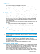
Flow of I/O requests using Hyper Parallel Access Volumes Multiple alias devices are assigned to a base device in a CU to enable the base device to handle multiple I/O requests. In Hyper Parallel Access Volumes, alias devices are pooled together in a single CU, meaning that all base devices in the CU share alias devices. In the following figure, three alias devices each are assigned to base devices 1, 2, and 3.
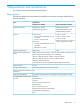
2 Requirements and specifications This chapter contains requirements and specifications. Requirements The following table lists the requirements for Parallel Access Volumes and Hyper Parallel Access Volumes operations. Item Software License Keys Requirements Parallel Access Volumes Hyper Parallel Access Volumes Parallel Access Volumes Parallel Access Volumes Workload Manager (WLM) Hyper Parallel Access Volumes Workload Manager (WLM) Host OS Dynamic mode z/OS 1.
Functions incompatible with Parallel Access Volumes Devices using Parallel Access Volumes can coexist in the same storage system but cannot be used concurrently with the following functions: • Open Volume Management • Cache Residency • LUN Manager • Business Copy • Continuous Access Synchronous • Continuous Access Journal Devices using Data Exchange cannot coexist in the same CU with devices using Parallel Access Volumes.
3 Defining devices This topic contains information on selecting base and alias device ratios, and procedures for defining LCUs and devices using HCD (hardware configuration definition). Parallel Access Volumes users use the HCD program to define logical control units (LCUs) and Parallel Access Volumes devices to the host system. Selecting optimum base/alias device ratio Optimizing the number of alias devices in a LCU is best done using analysis of RMF data.
3. Select option 4 to display the Control Unit List screen. 4. Press F11 on the keyboard to display the Add Control Unit screen.
5. Enter the following information: • Control unit number • Control unit type - 2105 or 2107 • Switch connection information Press Enter to display the Select Processor / Control Unit screen. 6. Select the processor complex that the control unit attaches to, and then press Enter to display the next Select Processor / Control Unit screen. 7. Select option 2 and then press Enter to display the next Select Processor / Control Unit screen.
8. Enter the following information: • chpids that attach to the control unit • the logical control unit address • the device starting address • the number of devices supported Defining a base or alias device Use the Hardware Configuration Definition (HCD) program to define a base or alias device on an LCU. Procedure 2 To define a base or alias device on an LCU: 14 1. From the ISPF/PDF primary options menu, select the HCD option to display the HCD main screen. 2.
3. Select option 5 to display the I/O Device List screen. 4. Press PF11 to display the Add Device screen. 5. Enter the following information: • Device Number • Number of devices • Parallel Access Volumes device type. Supported base device types are 3380B and 3390B and supported alias device types are 3380A and 3390A.
NOTE: The 3380A and 3380B devices are not related to the 3380-3A/B/C multiplatform devices. Similarly, the 3390A and 3390B devices are not related to the 3390-3A/B/C multiplatform devices. 16 6. Press Enter to display the Device / Processor Definition screen. 7. Select a Processor/System ID combination and then press Enter to display the Define Device / Processor screen. 8. Specify or revise any values and then press Enter to display the Define Device to Operating System Configuration screen.
9. Select the OS to connect or disconnect devices and press Enter to display the select / disconnect screen. 10. Select option 1 and press Enter to display the Define Device Parameters / Features screen. 11. Specify or revise any values. The DYNAMIC parameter controls whether Parallel Access Volumes is in dynamic or static mode. The WLMPAV parameter controls whether or not the device is supported by Workload Manager (WLM). These parameters are set to Yes by default.
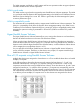
Procedure 3 To display configuration parameters for a device: 18 1. From the ISPF/PDF primary options menu, select the HCD option to display the HCD main screen. 2. Verify the name of the IODF or IODF.WORK I/O definition file to be used, and then select option 1 to display the Define, Modify, or View Configuration Data screen. 3. Select option 5 to display the I/O Device List screen.
4. Select the desired device by entering a slash (/) by the device number (in the preceding figure, device 8101 is selected), and press Enter to display the Actions on selected devices screen. 5. Select option 8 and press Enter to display the View Device Definition screen. 6. Review the information for accuracy and then press Enter to display the View Device / Processor Definition screen. 7. Select a Processor/System ID combination to display the View Device Candidate List screen.
8. Review the candidate list for this device and then press Enter to display the View Device / OS Configuration Definitions screen. 9. Select an OS to view more details and press Enter to display the View Device Parameter / Feature Definition screen. 10. Verify that the WLMPAV parameter is set to Yes.
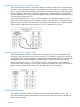
Address mapping between base and alias devices The unit address mapping for base and alias devices defined to the host operating system must match the address mapping defined for the P9500 control unit using the Remote Web Console. If the mappings do not match, serious issues can occur during data processing. The following figure shows examples of mappings between base devices and alias devices.
4 Preparing for Parallel Access Volumes operations This topic describes the necessary preparations to use Parallel Access Volumes with your system. Setting the WLM mode To use dynamic Parallel Access Volumes, the WLM must be set to goal mode. In goal mode, WLM can assign more or fewer aliases to a base device based on the host I/O activity to that device. To use static Parallel Access Volumes, the WLM must be set to compatibility mode.
4. 5. 6. Set the Dynamic alias management field to Yes and WLM is in goal mode. Set the field to No and WLM is in compatibility mode. The default setting is Yes. Set the I/O priority management field. The effect of this field setting depends on the Dynamic alias management setting. As shown in the following table, the setting of both of these fields controls whether the Dynamic Alias Algorithm is in effect.
2. Issue the following commands from z/VM system console to all alias devices that are used for Hyper Parallel Access Volumes in the corresponding CU to enable Hyper Parallel Access Volumes: DET alias_device_number1-alias_device_number2 VARY OFFLINE alias_device_number1-alias_device_number2 SET CU HYPERPAV ssid1-ssid2 VARY ONLINE alias_device_number1-alias_device_number2 ATT alias_device_number1-alias_device_number2* 3.
5 Performing Parallel Access Volumes operations This chapter describes performing Parallel Access Volumes operations on the storage system using the GUI. Assigning aliases to base volumes Up to 255 aliases can be assigned to one base device. If the number of selected free volumes is larger than the number of selected base volumes, the Parallel Access Volumes function attempts to allocate the free volumes equally to the base volumes.
No volumes are displayed if the selected CU image only contains devices to which aliases cannot be assigned, such as 3390-V type devices or journal volumes. In this case, select another CU image. 5. 6. 7. 8. 9. Select one or more base volumes in the Base Volume List. Press Ctrl and click to select multiple base volumes, press Shift + click to select a series of base volumes, or click Select All to select all base volumes in the CU image. Select one or more free volumes in the Free Volume List.
4. From the CU list, select the CU image which contains the aliases to be removed. Base volumes are displayed in the Base Volume List. No volumes are displayed if the selected CU image only contains devices to which aliases cannot be assigned, such as 3390-V type devices or journal volumes. In these cases, select another CU image. 5. Select one or more base volumes in the Base Volume List.
Reassigning aliases Alias volumes may be reassigned to a different base volume in the same or different CU image using the Parallel Access Volumes window. Prerequisites • Before an alias is reassigned, the user must confirm that the number of requests to the base device that the alias is moved from is less than 50 IOPS. This performance information is acquired using RMF (Resource Measurement Facility Report Analysis) or other available tools.
The used capacity is the sum of the capacities of base volumes which meet at least one of the following conditions: • Base volumes to which alias volumes are or were assigned through Remote Web Console • Base volumes that are accessed by alias volumes using Dynamic Parallel Access Volumes or Hyper Parallel Access Volumes The calculation of the used capacity can be time-consuming as it takes three minutes for each CU to calculate this value.
6 Verifying and monitoring devices This chapter describes the procedures for verifying base and alias devices on the system, and the syntax and description of the commands used to monitor Parallel Access Volumes activities from the host computer. Verifying base and alias device definition After you have defined the mapping between base and alias devices to the host operating system, you must verify that the host recognizes the devices as specified.
Procedure 10 To verify the status of the devices by CHP ID: 1. Run the MVS Display Matrix command for each CHP ID connected to the storage system. Use the following syntax for this command. D M=CHP(CHP_ID) The following figure shows a sample output of this command. 2. Verify that the information displayed by the Display Matrix command matches the device status that was defined when the generation definition was made. If the information is incorrect, the devices must be redefined to the host.
V Cross_OS_File_Exchange_Volume_1-Cross_OS_File_Exchange_Volume_2,ONLINE 3. After performing one of the preceding actions, reissue the DEVSERV QPAV command and check for the alias devices in the returned results. Verifying Hyper Parallel Access Volumes aliases from z/OS on z/VM When you restart a P9500 storage system while using Hyper Parallel Access Volumes, you must verify that the correct aliases are sustained to a CU.
5. Reissue the DEVSERV QPAV command and check for the alias devices in the returned results. Monitoring with MVS commands MVS commands can be used to monitor the Parallel Access Volumes activities on the P9500 from z/OS. For the complete syntax of MVS commands, see the IBM document OS/390 MVS System Commands (GC28–1781). DISPLAY command The MVS DISPLAY command displays path information and alias count for the specified base device. Use the following syntax for this command.
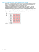
DEVSERV QPAV commands The MVS DEVSERV QPAV commands can be used for the following functions. • Display the status of Parallel Access Volumes base devices. Use the following syntax for this command. DS QP,device_unit_ID,4 The following figure shows a sample output of this command. • Display the status of a Hyper Parallel Access Volumes base device and its alias devices. Use the following syntax for this command. DS QP,device_unit_ID,HPAV The following figure shows a sample output of this command.
• Display the status of the host and storage system configuration. Use the following syntax for this command. DS QP,device_unit_ID,VOLUME The following figure shows a sample output of this command. DISPLAY IOS HYPERPAV command The MVS DISPLAY IOS HYPERPAV command displays the current HYPERPAV enablement status. Use the following syntax for this command.
D IOS,HYPERPAV The following figure shows a sample output of this command. GTF I/O tracing Parallel Access Volumes are compatible with GTF I/O tracing. When a device number is specified for a GTF I/O tracing operation, GTF determines if the device is a Parallel Access Volumes base device and automatically includes the alias addresses currently assigned to the base device. For more information on GTF I/O tracing, see the IBM document OS/390 MVS Diagnosis: Tools and Service Aids (SY28-1085).
NOTE: The QUERY CU command may only be executed on the OS that is used directly by the host computer. Any attempt to execute the QUERY CU command on the z/VM that is operated as a guest OS on the other z/VM is rejected. QUERY DASD DETAILS command The QUERY DASD DETAILS command displays information about DASD (RDEV). Use the following syntax for this command. Query DAsd DETAILS {rdev | rdev1 | rdev2} The following figure shows a sample output of this command.
QUERY VIRTUAL DASD DETAILS command The QUERY VIRTUAL DASD DETAILS command displays information about all DASDs that can be accessed by z/VM. Use the following syntax for this command. Query Virtual DAsd [DETAILS] The following figure shows a sample output of this command. CAUTION: The DETAILS operand is only valid for dedicated DASD and mini-disk DASD.
7 Troubleshooting This chapter provides troubleshooting information. Troubleshooting For troubleshooting information on Remote Web Console, see the HP XP P9000 Remote Web Console User Guide. For a complete list of Remote Web Console error codes, see HP XP P9000 Remote Web Console Messages.
8 Support and other resources Contacting HP For worldwide technical support information, see the HP Support Center: http://www.hp.
Conventions for storage capacity values P9000 disk arrays use the following values to calculate physical storage capacity values (hard disk drives): • 1 KB (kilobyte) = 1,000 bytes • 1 MB (megabyte) = 1,0002 bytes • 1 GB (gigabyte) = 1,0003 bytes • 1 TB (terabyte) = 1,0004 bytes • 1 PB (petabyte) = 1,0005 bytes • 1 EB (exabyte) = 1,0006 bytes P9000 disk arrays use the following values to calculate logical storage capacity values (logical devices): • 1 KB (kilobyte) = 1,024 bytes • 1 MB (megab
CAUTION: IMPORTANT: NOTE: TIP: 42 Indicates that failure to follow directions could result in damage to equipment or data. Provides clarifying information or specific instructions. Provides additional information. Provides helpful hints and shortcuts.
A Disabling Hyper Parallel Access Volumes This appendix describes the procedures for disabling Hyper Parallel Access Volumes on the storage system. Disabling Hyper Parallel Access Volumes from z/OS Prerequisites • All alias devices must be removed. • You must have the Storage Administrator (Provisioning) role to perform this task. Procedure 12 To disable Hyper Parallel Access Volumes from z/OS: 1.
Procedure 14 To disable Hyper Parallel Access Volumes from z/OS on z/VM: 1. From z/OS on z/VM, issue the following commands to all base devices in the corresponding CU. V base_device_number1-base_device_number2,OFFLINE CF CHP(channel_path1-channel_path2),OFFLINE 2. Issue the following command from the host system console to disable the Hyper Parallel Access Volumes option on the host computer. SETIOS HYPERPAV=NO 3.
B Parallel Access Volumes GUI reference This appendix describes the fields and options available in the Parallel Access Volumes window. Parallel Access Volumes window Use the Parallel Access Volumes window to assign alias devices to base devices. Item Description LDKC Selects the LDKC that contains the desired CU(s) and LDEV(s). CU Selects the logical CU image that contains the desired LDEV(s). The volume lists on the Parallel Access Volumes window display only the LDEVs for the selected CU image.
Base Volume List The Base Volume List box displays the LDEVs that are currently in use in the selected CU image. Each of these LDEVs can be a Parallel Access Volumes base device. When you assign and cancel aliases for base devices, you select the base devices from this list box. The following table describes the items in the Base Volume List box. Item Description Base Volume Displays the LDKC number, CU number, and LDEV number of the base volume.
Item Description indicates that eight free devices are selected out of a total of 47 free devices in the selected CU image. Select All Selects all volumes in the Free Volume List box.
Glossary CU Control Unit. Used to organize the storage space attached to the disk controller ( DKC). You can group similarly configured logical devices (LDEVs) with unique control unit images (CUs). CUs are numbered sequentially. The disk array supports a certain number of CUs, depending on the disk array model. Each CU can manage multiple LDEVs; therefore, both the CU number and the LDEV number are required to identify an LDEV. DFSMS Data Facility Storage Management Subsystem.
Index A O alias device definition, 5 assigning aliases to base devices, 25 overview, 5 B base device definition, 5 Base Volume List, 45 C contacting HP, 40 conventions document, 41 storage capacity values, 41 text symbols, 41 D defining a base or alias device on an LCU, 14 defining an LCU, 11 disk arrays supported models, 5 displaying configuration parameters for a device, 18 document conventions, 41 related information, 40 documentation HP website, 40 providing feedback, 40 dynamic mode, 6, 10 G GTF
Free Volume column, 46 Free Volume List, 45 Initial Base column, 46 LDKC list, 45 Used Capacity, 45 WLMPAV parameter, 6 Workload Manager (WLM) compatibility mode, 7 goal mode, 7 overview, 6 50 Index