HP P9000 External Storage for Open and Mainframe Systems User Guide Abstract This guide describes and provides instructions for using the HP P9000 External Storage for Open and Mainframe Systems software to configure and perform external storage operations on HP P9000 disk arrays. The topics that are covered include interoperability, prerequisites, troubleshooting, remote command devices, and a RAID Manager command reference.
© Copyright 2010 , 2011 Hewlett-Packard Development Company, L.P. Confidential computer software. Valid license from HP required for possession, use or copying. Consistent with FAR 12.211 and 12.212, Commercial Computer Software, Computer Software Documentation, and Technical Data for Commercial Items are licensed to the U.S. Government under vendor's standard commercial license. The information contained herein is subject to change without notice.
Contents 1 About External Storage...............................................................................8 Resources that can be executed for each function..........................................................................8 Unifying copy operations between different storage systems...........................................................8 Unifying connections from a host to different storage systems..........................................................
Choosing mapping policy........................................................................................................30 Port discovery and volume discovery....................................................................................30 System requirements................................................................................................................31 Storage systems supported as external storage systems...........................................................
Using existing data in the mapped external volume................................................................59 7 Troubleshooting........................................................................................61 General troubleshooting..........................................................................................................61 Troubleshooting the mapping path.......................................................................................62 Troubleshooting volume discovery.
System parameters for connecting IBM V7000 series..............................................................82 Notes on connecting IBM V7000 series................................................................................82 Notes on connecting IBM XIV series..........................................................................................82 Fujitsu FibreCAT CX series........................................................................................................
Disconnect External Storage Systems window...........................................................................128 Disconnect External Volumes window......................................................................................128 Assign Processor Blade wizard...............................................................................................129 Assign Processor Blade window.........................................................................................129 Confirm window...
1 About External Storage Unless otherwise specified, the term P9000 in this guide refers to the following disk array: • P9500 Disk Array The GUI illustrations in this guide were created using a Windows computer with the Internet Explorer browser. Actual windows may differ depending on the operating system and browser used. GUI contents also vary with licensed program products, storage system models, and firmware versions.
Figure 1 Unifying copy operations between different storage systems Unifying connections from a host to different storage systems When a system has multiple storage systems, a host usually needs to connect to all storage systems. When a system administrator configures the connections from a host to volumes, they need to follow the different instructions depending on the storage systems.
Figure 2 Unifying connections from a host to different storage systems 10 About External Storage
2 Interoperability with other products and functions You can use the P9500 program products to utilize and manage the external volumes you have set using External Storage. For the operations and notes on each program product, see the respective user guides. LUN Manager and Configuration File Loader If you set the emulation type for the open system as you map the external volume, you need to set the LU path for the mapped volume using LUN Manager.
Performance Monitor Consider the following for Performance Monitor: • Performance Monitor can be used to display the monitoring information about the external volumes. • Mapped volumes can be used for Auto LUN. For a configuration example of Auto LUN, see “Auto LUN operations ” (page 13). Continuous Access Synchronous and Continuous Access Synchronous Z Mapped volumes can be used for Continuous Access Synchronous and for Continuous Access Synchronous Z.
Examples of using external volumes with other products For the following P9500 program products, the examples of using external volumes are described in the following sections: • “Auto LUN operations ” (page 13) • “Continuous Access Synchronous operations” (page 14) • “Continuous Access Journal operations” (page 15) • “Business Copy operations” (page 16) • “Snapshot operations” (page 17) Auto LUN operations Figure 3 (page 14) shows the use of an external volume for the Auto LUN operation.
Figure 3 Example of the Auto LUN operation Continuous Access Synchronous operations Figure 4 (page 15) shows the use of an external volume for the Continuous Access Synchronous operation. The mapped external volume is set as the S-VOL of the Continuous Access Synchronous pair, and the volume in the local storage system that is connected as the multipoint control unit (MCU) is set as the P-VOL of the Continuous Access Synchronous pair.
Figure 4 Example of the Continuous Access Synchronous operation Continuous Access Journal operations Figure 5 (page 16) shows the use of an external volume for the Continuous Access Journal operation. The mapped external volume is set as the S-VOL of the Continuous Access Journal pair, and the volume in the local storage system that is connected as the MCU is set as the P-VOL of the Continuous Access Journal pair.
Figure 5 Example of the Continuous Access Journal operation Business Copy operations Figure 6 (page 17) shows the use of an external volume for the Business Copy operation. The mapped external volume is set as the S-VOL of the Business Copy pair, and the local storage system internal volume is set as the P-VOL of the Business Copy pair. For details on Business Copy, see the HP P9000 Business Copy User Guide. The procedure for the operation is as follows: 1.
Figure 6 Example of the Business Copy operation Snapshot operations “Example of the Snapshot operation” (page 18) shows the use of an external volume for the Snapshot operation. The mapped external volume is set as a pool-VOL of the Snapshot pair. For details on Snapshot, see the HP P9000 Snapshot User Guide. The procedure for the operation is as follows: 1. Use External Storage to map a volume in the external storage system as an internal volume of the local storage system.
Figure 7 Example of the Snapshot operation 18 Interoperability with other products and functions
3 Key terms This chapter explains key terms related to External Storage operation.
Remote Web Console computer User-supplied computer that operates Remote Web Console. External Storage A program product that enables the operation of multiple storage systems connected to the P9500 storage system as if they were all in one storage system and provides common management tools and software. External volume It is a volume in the external storage system mapped as a volume of the connected storage system by using External Storage.
Storage systems and external paths Before using External Storage, connect the Fibre Channel port of the local storage system to the external storage system port with the fiber cable. The route between ports, which is connected with the cable, is called the "external path". The Fibre Channel port of the local storage system is set to connect to the host by default.
4 Prerequisites This chapter describes the requirements and preparations for External Storage operations. Configuring External Storage Before configuring the External Storage settings, answer the following: • Which ports can be connected to external storage systems? See “Choosing external port” (page 22). • Which external storage system and volumes should be mapped as the internal virtual volumes? See “Choosing and mapping external volumes” (page 22).
You cannot map an external volume whose capacity is smaller than the minimum available capacity. For example, you cannot map an external volume of 10 GB as an internal volume requiring at least 30 GB. The maximum or minimum available capacity of an external volume depends on the emulation type that is set when the volume is mapped.
Residency operation, see the HP P9000 Performance for Open and Mainframe Systems User Guide. NOTE: When you set the cache mode, note the following: • Data that is not written by the host (for example, data written by Business Copy) is asynchronously destaged to the external storage system regardless of the Cache Mode setting.
the ports of the external storage system) will be displayed in a dialog box when you map an external volume. In this dialog box, you can set external paths by selecting the starting points and the ending points of the paths according to the actual cable connections. Setting of redundant external paths You can set redundant external paths (add alternate paths) when you set the external paths. You can also add an alternate path or change the priority after completing the mapping of the external volume.
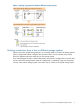
Figure 11 (page 26) illustrates an example of setting an alternate path when a switch is used. Two ports are specified in the local storage system, and connected to the ports in the external storage system through the switch. In this case, two ports of different clusters are specified in the local storage system. Therefore, the setting of the alternate path is enabled. In Figure 12 (page 26), two paths are also set between the internal volume and the external volume.
Figure 13 When the path mode is Multi mode Examples of switching I/O execution paths to alternate paths (when the path mode is Single mode) Figure 14 (page 28) shows an example of the case when the path mode is Single mode. When an error occurs in the path that is being used for I/Os, the I/O execution path is switched to the path with the second highest priority.
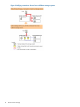
Figure 14 When the path mode is Single mode Examples of switching I/O execution paths to alternate paths (when the path mode is Single mode and there is at least one alternate path in Standby status) Figure 15 (page 29) shows an example of the case when the path mode is Single mode, and there are the alternate paths in the Normal status and the Standby status. Figure 16 (page 29) shows another example of the case when the path mode is Single mode.
Figure 15 Single mode with alternate paths in Normal and Standby Figure 16 Single mode with alternate paths in Standby only Configuring External Storage 29
Connecting mainframe volumes Mainframe volumes, that pre-exist on an external storage system and are accessed by FICON channels, cannot connect directly to the P9500 storage system as an external volume. The P9500 storage system does not recognize these volumes because of the fibre channel.
You can set the mapping policy in advance and choose whether to execute port discovery automatically or manually. If port discovery is executed automatically, WWNs connected to all the external ports of the local storage system will be searched for. If port discovery is executed manually, you can select a specific external port and limit the scope to search WWNs. If you can specify which external port to search for, you can reduce the operation time by executing the port discovery manually.
Supported external storage systems are listed on the HP Single Point of Connectivity Knowledge (SPOCK) website: http://www.hp.com/storage/spock. External Storage requirements The following table describes the External Storage requirements.
• Make sure that an external volume is accessed only from the local storage system side once the external volume is mapped. ◦ Make sure that the external volume, which has been mapped as an internal virtual volume, is not accessed from a host that is connected to the external storage system. ◦ Make sure that the external volume, which has been mapped as an internal virtual volume, is not manipulated by a copy function or some other functions of the external storage system.
Table 3 When the emulation type of the external volume is for Mainframe (continued) Application HDD type SAS/FC/Flash Drive SATA Operation from TPF Not Supported Not Supported File Operation from Host OK Not Recommended OK OK Backup OK Recommended Archive OK Recommended (Journal, Check points) (Both of Read and Write) File Operation from Host (Mainly Read) Capacity guidelines • When a volume, which has a capacity of 4 TB or less, in the external storage system (external volume) is mapped
Figure 18 When the external volume capacity is bigger than the basic capacity of specified emulation type (example of the OPEN-3 emulation type) Figure 19 When the external volume capacity is smaller than the basic capacity of specified emulation type Guidelines for mainframe volumes • If you plan to use the mapped external volume from the mainframe operating system (for example, the volume is mapped with the setting of 3390-x mainframe emulation type), you need to select the external volume that consist
• For the external volume, for which the Cache Mode is set to Disable, the bind mode for the Cache Residency operation is not available. • If you use the mapped external volume for the Cache Residency operation and set the bind mode, the cache of twice as much capacity as the user data is required for the Cache Residency operation. Creating LUSE volume guidelines • LUSE is not supported with mainframe volumes. • Do not combine LDEVs of multiple external volumes to create a LUSE volume.
system, the processing speed of Read and Write operations becomes slow. In this case, the I/Os from the mainframe host may become MIH error. • If the host connected to the local storage system issues too many I/Os to be processed by the external storage system, the commands from the host may possibly be timed out.
For more information about setting the queue of commands, see “Changing the port setting of the external storage system” (page 56). • When using external volumes of AMS2000 series storage system with a copying program product, the copy operation needs to be distributed to two or more RAID groups. There is an upper bound to the number of pairs that can be used for initial copy or resynchronization.
5 Flowchart This chapter describes the flowchart of the External Storage operations. Overview of operations to make external volumes usable from a host The following flowchart illustrates External Storage operations that make external volumes usable from a host. Figure 20 Making external volumes usable from a host The procedure for making the external volumes usable from a host follows: 1. Prepare a volume in the external storage system. 2.
Overview of operations after making external volumes usable from a host After making external volumes usable from a host, External Storage enables you to execute the following operations. Preparing to manipulate the power supply of the storage systems You must follow specific procedures if you want to manipulate the power supply of the storage systems when external volumes are used.
6 Performing External Storage operations This chapter explains how to set the external volume using External Storage. Setting ports Setting ports of external storage systems This section describes the procedure for setting the ports of the external storage system. For detailed information, see the documentation for the external storage system you use. To set the port of the external storage system: 1. 2. 3. 4. Set the topology information according to the configuration of the connection (fabric or loop).
5. Select external volumes from the Discovered External Volumes list and enter the external volume group number and their sequential number in the Initial Parity Group ID box, and then click Add. Select whether to create LDEVs in the external volume in Allow Simultaneous Creation of LDEVs. If you want to take over the data of the external volume when you create LDEVs, select Yes in Use External Storage System Configuration, and then enter an LDEV name in the LDEV Name box.
NOTE: When you detach the channel adaptor where external paths exist, it is necessary to delete all external paths beforehand. When the channel adaptor is detached without deleting external paths, it fails in detaching the channel adaptor. Create new path group and configure external paths To create a new path group and configure external paths, you need to perform the mapping operation. For details of the mapping operation, see “Mapping an external volume” (page 41).
Change configured external path priority To change the external path priority, use the Raise Priority command and the Lower Priority command. The following is an example of procedure to make the external path to the currently used path by raising the priority of the external path: To make the external path to the currently used path by raising the priority of the external path: 1. Click External Storage in the Storage Systems tree. The list of available external storage systems appear in the tree. 2.
Changing an external path To change the external path, cancel the current external path configuration (see “Cancel external path configuration” (page 44)), and configure another external path as a new external path (see “Add external path to existing path group” (page 43)). Replace all external paths with newly added external paths This section explains how to change all the current external paths to newly added external paths with an example.
Take the following steps to delete the external path B and add the external path D. 6. 7. Execute the Disconnect External Paths command on the external path B. Disconnect the cable that the external path B uses, and connect the cable that the external path D uses. 8. Cancel the configuration of the external path B, and add the external path D. 9. Click Apply to apply the settings of the external paths B and D. 10. Make sure the status of the external path D is Normal.
To execute the Disconnect External Storage Systems command, see “Disconnecting external storage system or external volume” (page 50). NOTE: When you want to perform the same processing of the Disconnect External Storage Systems command on an individual volume, you can use the Disconnect External Volumes command. If you want to delete the external volume mapping individually, you first need to execute the Disconnect External Volumes command and then the Delete External Volumes command.
To execute the Disconnect External Storage Systems command, see “Disconnecting external storage system or external volume” (page 50). 4. 5. Perform other operations that are required before turning off the local storage system, if there is some. Turn off the power supply of the external storage system. CAUTION: After you have executed the Disconnect External Storage Systems command, but you need to use the mapped external volume again, execute the Reconnect External Storage Systems command.
To turn on the power supply of the local storage system to restart from the turned off status: 1. 2. Turn on the external storage system that contains the external volume, which is mapped as an internal volume. Turn on the power supply of the local storage system. CAUTION: • When the local storage system is turned off after the Disconnect External Storage Systems command is executed, you cannot access the mapped external volume from the local storage system as you just turn the local storage system on.
4. Start the read or write I/O to the local storage system. All read and write I/Os with fibre channel connections should be started. Disconnecting external storage system or external volume Use the Disconnect External Storage Systems command and the Disconnect External Volumes command to disconnect the external volume.
Note the following when executing the Disconnect External Storage Systems command and the Disconnect External Volumes command. • After executing the Disconnect External Storage Systems command or the Disconnect External Volumes command, click Refresh View on the Remote Web Console main window to update the information, and check the current progress status.
8. Click Apply in the Confirm window. The settings are applied to the local storage system and the displayed information for the external volume status in the window becomes Cache Destage. When all the data in the cache memory is written to the external volume, the displayed information for the external volume status in the window becomes Disconnect. When an error occurs, an error message appears. Verify the details in the Confirm window.
3. 4. 5. 6. Select the external storage system. On the menu bar, click Actions, External Storage, and then Reconnect External Storage Systems. The Reconnect External Storage Systems window opens. Confirm the settings and enter the task name in the Task Name box. Click Apply in the Confirm window. The displayed information for the external volume status in the window changes to Checking.
4. 5. 6. 7. 8. On the menu bar, click Actions, External Storage, and then Disconnect External Paths. The Disconnect External Paths window opens. Select one of the following from Disconnect external paths. • By Ports: Displays the ports in the local storage system. Select By Ports to stop the use of all the external paths connected to the specified port in the local storage system. • By External WWNs: Displays the WWNs in the external storage system.
Cache mode and pool volumes When a volume is registered to a pool as a pool volume, the cache mode setting should be the same among all the pool volumes in the pool. Cache mode and remote command devices When the volume is a remote command device, you cannot change the cache mode from Disable to Enable. To change the cache mode of the external volume: 1. Click External Storage in the Storage Systems tree. The list of available external storage systems appear in the tree. 2.
Changing the port setting of the external storage system You can change the setting of the port of the external storage system in the Edit External WWNs window. CAUTION: • If the default setting has no problem, use the default setting as it is. • For the volume used in usual I/O, set I/O Timeout within 15 seconds. • For changing the setting, match the value to the recommended value of the external storage system. To change the port setting of the external storage system: 1.
Command device If the execution of any application that is using the command device is in progress, stop the application. Destage cache memory data All the data in the cache memory must be written into the mapped external volume using the Disconnect External Storage Systems command or the Disconnect External Volumes command. LUSE volumes When it is set as a volume that configures a LUSE volume, you cannot delete the external volume mapping.
NOTE: When you click Yes, the Delete External Volumes operation is performed, however, the data in the cache memory that is not written to the volume is not guaranteed. 8. Click Finish to display the Confirm window. 9. Confirm the settings and enter the task name in the Task Name box. 10. Click Apply in the Confirm window. NOTE: The operation cannot be performed if some parts of the local storage system are blocked.
3. If you set the emulation type for the mainframe system when you map the volume, the status of the mapped volume becomes Blockade. Format the volume using the Virtual LVI function. For zero-formatted external volumes, when you select that volume to map, you can use the Virtual LVI function to perform the Write to Control Blocks operation to restore the volume.
NOTE: • Make sure that you do not access the external volume, which has been mapped as a internal volume, from the host that is connected to the external storage system. Also make sure that you do not access the mapped external volume using the function (for example, copy function) of the external storage system. Once you have mapped an external volume as an internal volume, you can access the mapped external volume only from the local storage system side.
7 Troubleshooting This chapter provides troubleshooting information for External Storage. General troubleshooting Table 5 (page 61) provides general troubleshooting instructions for External Storage operations. If you need to call HP Technical Support, see “Support and other resources” (page 66) for instructions. Table 5 General troubleshooting for External Storage Error Corrective action The Remote Web Console computer cannot access Remove the error and retry the operation. the external volume.
Table 5 General troubleshooting for External Storage (continued) Error Corrective action The reason for the error could be as follows: • All the set paths are blocked (paths are not connected). • The attribute of external volume is not set to Read/ Write attribute. • The external volume is blocked by error. “?” is displayed in the LUN ID(Highest Priority) A corresponding external volume was not found from the external column of the Discovered External Volumes table. path with the highest priority.
Table 6 Mapping path statuses and required actions Status Description Action Unknown The status of the path is unknown. The status of the path cannot be identified. Call HP Technical Support. Blockade The external port is blocked. The external port is blocked because of the microcode replacement or package replacement or some other factor. Check the status of the local storage system. If you cannot restore the path, call HP Technical Support.
Table 6 Mapping path statuses and required actions (continued) Status Description Action Unknown port The port attribute of the external storage system is Check the condition of the connection (for unknown. example, cables, switches) to the external storage system. If you cannot restore the path, call HP Technical Support. Cannot detect port The path has been removed or the port of the Check the condition of the connection to the external storage system cannot be found.
Table 7 Causes of volume discovery failure and required actions (continued) Cause Action External volume returned RESERVATION CONFLICT. Release the reserved state of the external volume. Port security is set on the external storage system. Cancel the port security setting or change the security of the external storage system so that the local storage system can access the port of the external storage system. No LU is configured on the port of the external storage system.
8 Support and other resources Contacting HP For worldwide technical support information, see the HP support website: http://www.hp.
HP websites For additional information, see the following HP websites: • http://www.hp.com • http://www.hp.com/go/storage • http://www.hp.com/service_locator • http://www.hp.com/support/manuals • http://www.hp.com/support/downloads • http://www.hp.
Table 8 Document conventions (continued) Convention Element Monospace text • File and directory names • System output • Code • Commands, their arguments, and argument values Monospace, italic text • Code variables • Command variables Monospace, bold text WARNING! CAUTION: IMPORTANT: NOTE: TIP: 68 Emphasized monospace text Indicates that failure to follow directions could result in bodily harm or death. Indicates that failure to follow directions could result in damage to equipment or data.
A Connecting external storage systems This appendix provides configuration information for connecting various external storage systems to the P9500 storage system. AMS/WMS storage system System parameters The following table explains whether to specify system parameters when making settings on ports on the AMS and WMS storage systems. You can either specify or omit any other parameters.
Relationship between serial number and AMS/WMS model When the external storage system is AMS or WMS, you can identify the storage system model from the serial number displayed in the Serial Number column in the Volume Operation window. The following table describes the relationship between the serial number displayed in the Serial Number column and the storage system model.
Table 11 Relationship between WWN of port and controller (AMS/WMS) (continued) Model Controller WWN of port XXXXXXXXXXXXXXX6 XXXXXXXXXXXXXXX7 Controller 1 XXXXXXXXXXXXXXX8 XXXXXXXXXXXXXXX9 XXXXXXXXXXXXXXXA XXXXXXXXXXXXXXXB XXXXXXXXXXXXXXXC XXXXXXXXXXXXXXXD XXXXXXXXXXXXXXXE XXXXXXXXXXXXXXXF In WWNs, "X" is an arbitrary number or character. The ports in the same apparatus have the identical value.
If the status of the external volume changes to Blockade, the external volume will be automatically restored in several hours. You can also manually restore the external volumes by using the Reconnect External Volumes command. Thunder 9500V storage system System parameters The following table explains whether to specify system parameters when making settings on ports on the Thunder 9500V storage system.
When you use the Thunder 9500V storage system as an external storage system, the following versions are recommended. If you use a 9500V storage system whose version is earlier than the following versions, the information about the SATA drive may not be displayed correctly.
Table 16 Path status and examples of recovery procedure (9500V) Path status Examples of recovery procedure External device setting changed Settings of the LU paths may have been changed by LUN Management. Check the settings of the LU paths. If the settings of the LU paths have been changed, change the settings back to the ones when the volume is mapped. Or use External Storage to perform the Delete LU operation and perform the Add LU operation again.
Table 17 Path status and examples of recovery procedure (P9500) (continued) Path status Examples of recovery procedure or some other copy program. If the volume is set as a pair volume, the volume may be protected because of the pair status. When the volume is protected, change the pair status or delete the pair. The access attribute of the volume may have been changed by Data Retention. Check the access attribute of the volume. If the volume is protected by the access attribute, release the protection.
Table 18 Path status and examples of recovery procedure (XP24000/XP20000 Disk Array) (continued) Path status Examples of recovery procedure Make sure that the Fibre cable is connected properly, and then set the Fibre Channel port properly using LUN Manager. The LUN security may have been enabled by LUN Manager. Check if the LUN security is enabled or not. If the LUN security is enabled, disable the LUN security.
Table 19 Path status and examples of recovery procedure (XP12000 Disk Array/XP10000 Disk Array) (continued) Path status Examples of recovery procedure Make sure that the Fibre cable is connected properly, and then set the Fibre Channel port properly using LUN Manager. The LUN security may have been enabled by LUN Manager. Check if the LUN security is enabled or not. If the LUN security is enabled, disable the LUN security.
Path status and examples of recovery procedure This section describes errors that require recovery operation on the external storage system side when the path status is not normal. When the path status is not normal, see the following table to recover the path status. If you cannot restore the path, call HP Technical Support (see “Support and other resources” (page 66)).
Table 22 Path status and examples of recovery procedure (SVS200) (continued) Path status Examples of recovery procedure The access attribute of the volume may have been changed by LUN Security XP Extension. Check the access attribute of the volume. If the volume is protected by the access attribute, release the protection. Cannot detect port There is a problem with connection to the external storage system. The possible causes are: • The Fibre cable is not physically connected in the proper way.
Figure 24 Configuration example for which logical volumes cannot be identified only by characteristic Oracle StorEdge 6120/6320 When connecting a Oracle StorEdge 6120/6320 as an external storage system, set the system parameters of the Oracle StorEdge 6120/6320 according to the following table. For the system parameters that are not in the following table, see the documentation of the Oracle StorEdge 6120/6320 and set the parameters appropriately for the connecting configuration.
EMC CLARiiON CX series When you connect an EMC CLARiiON CX series as an external storage system, set the system parameters of the EMC CLARiiON CX series according to the following table. For system parameters not in the following table, see the EMC CLARiiON CX series documentation and set the parameters appropriately for the connecting configuration.
IBM V7000 series System parameters for connecting IBM V7000 series When you connect an IBM V7000 series as an external storage system, set the system parameters of the IBM V7000 series according to the following table. For the system parameters that are not in the following table, see the documentation of the IBM V7000 series and set the parameters appropriately for the connecting configuration.
table, see the documentation for the SGI IS4600 series and set the parameters appropriately for the connecting configuration. Table 34 System parameter for connecting SGI IS4600 series Parameter Parameter setting host type When alternate paths are connected to different clusters on the SGI IS4600 series side: Linux Non-HP storage systems When connecting a non-HP storage system as the external storage system, the non-HP storage system port must be configured as a target attached to a Windows host.
B Required external volume capacity for each emulation type When you map an external volume as an internal volume, you need to specify the emulation type for the mapped volume. This appendix describes required external volume capacity corresponding to the specified emulation type. Determining required external volume capacity The capacity required for the external volume to be mapped is the total capacity of LDEVs created in the external volume.
Figure 25 LDEV capacity Figure 26 Determining the capacity required for the external volume (OPEN-3) When the capacity of the external volume is 1,610,612,640 (Blocks) and this external volume is mapped with OPEN-3 emulation type, 334 LDEVs, each of which has the base LDEV capacity, can be created at the maximum because the base LDEV capacity of OPEN-3 is 4,818,240 (Blocks). When 334 LDEVs are created, 1,320,480 (Blocks) of the mapped external volume becomes the free space.
For the emulation type for the open system other than OPEN-V, the LDEV capacity that can be made when an external volume is mapped is divisible by 1,440 blocks. For the emulation type for the mainframe system, the LDEV capacity that can be made when an external volume is mapped is an integer when converted into a cylinder.
C Adjusting volume capacities for pairs This appendix provides information for adjusting volume capacities for pairs. Adjusting volume capacities When you create a pair, the capacity of an S-VOL must be the same as that of a P-VOL. To set a desired volume to a pair, you may need to adjust the capacity of the volume. This section describes the procedure for adjusting the volume capacity. For “A,” “B,” and “C” in the following description, see Figure 27 (page 87).
Figure 28 Copying data to an external storage system (setting an external volume as S-VOL) 88 Adjusting volume capacities for pairs
D Remote command devices This appendix describes how to use remote command devices as command devices. Overview of remote command devices A remote command device is a device in the local storage system to which a command device in the external storage system is mapped. As you send the RAID Manager commands to the remote command device, you can enter these RAID Manager commands to the command device of the external storage system to operate the RAID Manager in the external storage system.
◦ Workgroup Modular Storage ◦ SANRISE 9900V series ◦ SANRISE 9500V series ◦ TagmaStore Universal Storage Platform ◦ TagmaStore Network Storage Controller ◦ XP1024/XP128 Disk Array series ◦ Thunder 9500V series ◦ Lightning 9900V series ◦ VP9500 ◦ H24000 ◦ H20000 ◦ SANRISE H12000 ◦ SANRISE H10000 ◦ SANRISE H1024/H128 ◦ P9500 ◦ XP24000 ◦ XP20000 ◦ XP12000 ◦ XP10000 ◦ XP1024/XP128 • You do not need the license for External Storage to map a command device as a remote comm
Table 36 Information displayed in Device Name column for remote command device (continued) Storage system Information displayed in Device Name column XP24000 Disk Array Example: OPEN V-CM, OPEN-3-CM XP20000 Disk Array SANRISE Universal Storage Platform SANRISE Network Storage Controller SANRISE 9900V series TagmaStore Universal Storage Platform TagmaStore Network Storage Controller XP1024/XP128 Disk Array VP9500 H24000 H20000 SANRISE H12000 SANRISE H10000 SANRISE H1024/H128 P9500 XP24000 XP20000 XP12000
Table 37 Remote command device restrictions Item Restriction Emulation type OPEN-V Number of LDEVs in an external volume 1 Cache mode Disable Minimum capacity 96,000 Blocks (about 47 MB) Maximum capacity 4TB • The remote command device cannot be identified by the port discovery or volume discovery process of External Storage.
E RAID Manager command reference This appendix describes RAID Manager commands that correspond to GUI actions. Action names and RAID Manager commands The following table lists actions in Remote Web Console and the corresponding RAID Manager commands.
F External Storage GUI reference This appendix explains the External Storage windows. For information about common operation such as buttons and task entry, see the HP P9000 Remote Web Console User Guide. Top window when selecting External Storage This window appears when you select External Storage in Storage Systems. • “Summary” • “External Storage Systems tab” • “External Paths tab” Summary Item Description Number of External Storage Systems Displays the number of external storage systems.
External Storage Systems tab Only the external storage systems to which the external volume assigned to the user belongs and the external storage systems that are connected with the port assigned to the user are displayed. Item Description Vendor / Model / Serial Number Vendor, model, and serial number of the external storage system. When the link is clicked, it changes to a top window when the external each storage system is selected. Status Status of external storage systems. • Normal: It is normal.
Item Description • Warning: There are external paths whose status is not normal. Check the status of the external paths in the View External LUN Properties window. • Blockade: The external path is blocked. QDepth The number of Read/Write commands which can be issued (queued) to the external volume at a time. The value that can be set ranges from 2 to 128. I/O Timeout (sec.) Value specified as the time over of the I/O to the external volume. The value that can be set ranges 5 to 240 (in second).
• “Summary” • “External Path Groups tab” Summary Item Description Status Status of external storage systems. • Normal: It is normal. • Disconnect: Connecting to the external storage system or the external volume is intentionally stopped using the Disconnect External Storage Systems command or the Disconnect External Volumes command. • Checking: The checking of the mapping path status is in progress. • Unknown: The status of the mapping path is unknown.
Item Description Number of External Path Groups Displays the number of external path groups. Number of External Volumes Displays the number of external volumes. External Volume Capacity Displays the total capacity of mapped external volumes. External Path Groups tab Only the external storage systems to which the external volume assigned to the user belongs and the external storage systems that are connected with the port assigned to the user are displayed.
• “Summary” • “Mapped Volumes tab” • “External Paths tab” Summary Item Description Status Status of path groups. • Normal: It is normal. • Disconnect: Connecting to the external storage system or the external volume is intentionally stopped using the Disconnect External Storage Systems command or the Disconnect External Volumes command. • Checking: The checking of the mapping path status is in progress. • Unknown: The status of the mapping path is unknown.
Mapped Volumes tab Only the external volumes assigned to the user are displayed. Item Description Parity Group ID Displays parity group numbers. Status Status of external volumes. • Normal: It is normal. • Disconnect: Connecting to the external storage system or the external volume is intentionally stopped using the Disconnect External Storage Systems command or the Disconnect External Volumes command. • Checking: The checking of the mapping path status is in progress.
Item Description Path Mode Path mode of the external path. • Single: Only the external path with the highest priority (primary path) is used to execute the I/O to the external volume. When an error occurs in the primary path, the path with the second highest priority is used. • Multi: All of the configured external paths are used at the same time. The multiple paths are used to execute the I/Os to the external volume distributing the work load.
Item Description I/O Timeout (sec.) Value specified as the time over of the I/O to the external volume. The value that can be set ranges 5 to 240 (in second). Path Blockade Watch(sec.) The time from when the connection of all the external paths to the external volume have been down to when the external volume is blocked. The value that can be set ranges from 5 to 180 (seconds). Edit External Path Configuration Displays the Edit External Path Configuration window.
Available External Path Groups table Only the external path groups that are composed only of the port assigned to the user are displayed. Item Description External Path Group ID Displays the name of the path group. External Path (Highest Priority) The highest priority external path in the path group. Port ID The port number in the local storage system connecting to the external storage system. External WWN Identification number of the port in the external storage system.
Discovered External Volumes table Item Description LUN ID(Highest Priority) Displays the LUN which is connected to the external path with the highest priority. “?” indicates that a corresponding external volume is not found from the external path with the highest priority. Confirm the connection with the external storage system that has failed in the volume discovery, and perform the operation again. Device Name Name of the storage system that is reported to the host by the external volume.
Item Description SSD is displayed when the external volume is the SSD of following storage systems. Operate SSDs according to the method of operating each storage system. • P9500 storage system • XP24000/XP20000 Disk Array Discovery Result Displays the error code when a error is found. When the link is clicked, the Discovery Result Detail window is displayed and details of the search result can be confirmed. Initial Parity Group ID Enter the parity group number.
CU Enter the CU number. The value that can be set ranges from 00 to FE. 00 is input by default. DEV Enter the LDEV ID. The value that can be set ranges from 00 to FF. 00 is input by default. Interval Specify the interval between LDEV IDs. The value that can be set ranges from 0 to 255. 0 is input by default. View LDEV IDs Displays the View LDEV IDs window. Initial SSID Enter the SSID. The value that can be set ranges from 0004 to FFFE. 0004 is input by default.
Add Adds external volumes selected from the Discovered External Volumes table to the Selected External Volumes table. Selected External Volumes table Item Description LUN ID(Highest Priority) Displays the LUN which is connected to the external path with the highest priority. Device Name Name of the storage system that is reported to the host by the external volume. The displayed items differ depending on the vendor of the storage system.
Item Description Base Emulation Type The emulation type of the mapped external volume. Top LDEV ID Displays LDEV ID of the top LDEV allocated to the external volume. Top LDEV Name Displays LDEV name of the top LDEV allocated to the external volume. Number of LDEVs Displays the number of LDEVs allocated to the external volume. Capacity Capacity of the external volume. SSID Displays SSIDs. CLPR CLPR used for accessing to the mapped external volume. MP Blade ID Displays processor blade IDs.
Selected External Paths table Item Description Priority Priority of path groups. Port ID The port number in the local storage system connecting to the external storage system. External WWN Identification number of the port in the external storage system. Selected External Volumes table Item Description LUN ID(Highest Priority) Displays the LUN which is connected to the external path with the highest priority.
Edit Policies window Allow Simultaneous Creation of LDEVs Select whether to create LDEVs in the external volume at the same time as the mapping of the external volume. Yes is selected by default. When Yes is selected, Base Emulation Type becomes nonrevitalization. Base Emulation Type Select the emulation type of the external volume from the list. Cache Partition Select CLPR used for accessing to the mapped external volume from the list. The value that can be selected ranges from CLPR0 to CLPR31.
Edit External Volumes wizard Edit External Volumes window Cache Mode Indicates whether the write data from the host to the external storage system is propagated synchronously (Disable) or asynchronously (Enable). The value set to the selected external volume is set by default. When two or more volumes with different values are selected, neither is set by default.
Selected External Volumes table Item Description Parity Group ID Displays parity group numbers. Top LDEV ID LDEV ID of the top LDEV created in the external volume. Top LDEV Name LDEV name of the top LDEV created in the external volume. Cache Mode Indicates whether the write data from the host to the external storage system is propagated synchronously (Disabled) or asynchronously (Enabled).
Available External Paths table Only the external paths that are connected with the port assigned to the user are displayed. Item Description Port ID The port number in the local storage system connecting to the external storage system. External WWN Identification number of the port in the external storage system. Add Adds external paths selected from the Available External Paths table to the Selected External Paths table. Remove Removes external paths from the Selected External Paths table.
Selected External Paths table 114 Item Description Priority Priority of external paths. Port ID The port number in the local storage system connecting to the external storage system. External WWN Identification number of the port in the external storage system. Raise Priority Raise the priority of the selected external path. Lower Priority Lower the priority of the selected external path.
Confirm window Selected External Path Group table Item Description External Path Group ID Displays the name of the path group. Vendor / Model / Serial Number Vendor, model, and serial number of the external storage system. Selected External Paths table Item Description Priority Priority of external paths. Port ID The port number in the local storage system connecting to the external storage system. External WWN Identification number of the port in the external storage system.
Edit External WWNs wizard Edit External WWNs window QDepth The number of Read/Write commands which can be issued (queued) to the external volume at a time. The value that can be set ranges from 2 to 128. 8 is input by default. The value set to the selected external path is displayed. When two or more paths with different values are selected, blank is displayed by default. I/O Timeout Value specified as the time over of the I/O to the external volume. The value that can be set ranges 5 to 240 (in second).
Confirm window Selected External WWNs table Item Description Port ID Displays name of ports. External WWN Identification number of the port in the external storage system. QDepth The number of Read/Write commands which can be issued (queued) to the external volume at a time. The value that can be set ranges from 2 to 128. I/O Timeout (sec.) Value specified as the time over of the I/O to the external volume. The value that can be set ranges 5 to 240 (in second). Path Blockade Watch(sec.
Delete External Volumes wizard Delete External Volumes window Selected External Volumes table Item Description Parity Group ID Displays parity group numbers. Top LDEV ID LDEV ID of the top LDEV created in the external volume. Top LDEV Name LDEV name of the top LDEV created in the external volume. Have you already disconnected external volume of above table? Click Yes if you have already performed the Disconnect External Storage Systems command or the Disconnect External Volumes command.
Confirm window Selected External Volumes table Item Description Parity Group ID Displays parity group numbers. Top LDEV ID LDEV ID of the top LDEV created in the external volume. Top LDEV Name LDEV name of the top LDEV created in the external volume. Forcible Deletion Yes is displayed when the external volume is forcibly deleted even if the connection to the external volume has not been disconnected.
Disconnect External Paths wizard Disconnect External Paths window Disconnect external paths Select By Ports to stop the use of all the external paths connected to the specified port in the local storage system. Select By External WWNs to stop the use of all the external paths connected to the specified WWNs (ports) in the external storage system. By Ports is selected by default.
Reconnect External Paths wizard Reconnect External Paths window Reconnect external paths Select By Ports to restore all the external paths connected to the specified port in the local storage system. Select By External WWNs to restore all the external paths connected to the specified WWNs (ports) in the external storage system. By Ports is selected by default.
Discover External Target Ports window Available External Ports table Only the external ports assigned to the user are displayed. Item Description Port ID The port number in the local storage system connecting to the external storage system. Add Adds ports selected from the Available External Ports table to the Selected External Ports table. Remove Removes ports from the Selected External Ports table.
External Paths Displays the information about external paths. Discover External Target Ports Displays the Discover External Target Ports window. Select the port that connects to the WWN in the Discover External Target Ports window. External Storage System Select the external storage system. When there is no external path in the Selected External Paths table, External Storage System becomes revitalization.
Selected External Paths table Item Description Priority Priority of external paths. Port ID The port number in the local storage system connecting to the external storage system. External WWN Identification number of the port in the external storage system. Raise Priority Raise the priority of the selected external path. Lower Priority Lower the priority of the selected external path. Change Setting window Initial Parity Group ID Enter the parity group number.
Processor Blade Select the processor blade. The value that can be selected ranges from MPB0 to MPB7. However, the value that can be selected changes according to the configuration of the device.Auto can be selected when there is a processor blade which can be assigned automatically. The value set to the selected external volume is set by default. When two or more volumes with different values are selected, blank is displayed by default.
External LUNs table Item Description Parity Group ID Displays parity group numbers. Priority Priority of external paths. Port ID The port number in the local storage system connecting to the external storage system. External WWN Identification number of the port in the external storage system. LUN ID When the external paths is connected to the selected external volume, LUN is displayed. Status Status of external paths. • Unknown: The status of the mapping path is unknown.
Reconnect External Storage Systems window Selected External Volumes table Item Description Parity Group ID Displays parity group numbers. Top LDEV ID LDEV ID of the top LDEV created in the external volume. Top LDEV Name LDEV name of the top LDEV created in the external volume. Vendor / Model / Serial Number Vendor, model, and serial number of the external storage system.
Item Description Top LDEV Name LDEV name of the top LDEV created in the external volume. Vendor / Model / Serial Number Vendor, model, and serial number of the external storage system. Disconnect External Storage Systems window Selected External Volumes table Item Description Parity Group ID Displays parity group numbers. Top LDEV ID LDEV ID of the top LDEV created in the external volume. Top LDEV Name LDEV name of the top LDEV created in the external volume.
Selected External Volumes table Item Description Parity Group ID Displays parity group numbers. Top LDEV ID LDEV ID of the top LDEV created in the external volume. Top LDEV Name LDEV name of the top LDEV created in the external volume. Vendor / Model / Serial Number Vendor, model, and serial number of the external storage system. Assign Processor Blade wizard Assign Processor Blade window Processor Blade Select the processor blade. The value that can be selected ranges from MPB0 to MPB7.
Selected External Volumes table Item Description Parity Group ID Displays parity group numbers. Top LDEV ID LDEV ID of the top LDEV created in the external volume. Top LDEV Name LDEV name of the top LDEV created in the external volume. MP Blade ID Displays processor blade IDs. External LDEV Properties window LDEVs table Item Description LDEV ID Displays LDEV IDs allocated to the external volume. LDEV Name Displays LDEV names. Parity Group ID Displays parity group numbers.
Glossary CHA Channel adapter. A device that provides the interface between the array and the external host system. Occasionally, this term is used synonymously with the term channel host interface processor (CHIP). CLI Command-line interface. An interface comprised of various commands which are used to control operating system responses. CLPR Cache logical partition.
RAID group A group of disks configured to provide enhanced redundancy, performance, or both. Specifically, four or eight physical hard disk drives (HDDs) installed in a P9000 or XP disk array and assigned a common RAID level. In an XP disk array this is also referred to as an array group or parity group. RAID level A configuration of disk drives that uses striping, mirroring, and parity to improve performance and data availability and reliability.
Index A R attributes list of emulation type, 23 Auto LUN, 13 related documentation, 66 remote command device, 89 B storage capacity values conventions, 67 Subscriber's Choice, HP, 66 symbols in text, 68 system requirements, 31 block management, ExG, 23 C cache logical partition, 24 memory, 23 channels ficon, 30 CLPR, 24 contacting HP, 66 conventions document, 67 storage capacity values, 67 text symbols, 68 D destaging data, 23 document conventions, 67 related information, 66 documentation HP website