HP P9000 Continuous Access Synchronous User Guide Abstract This guide explains how to use HP XP P9000 Continuous Access Synchronous Software to protect information stored on HP P9000 disk arrays from local disaster by continuously copying local data across Fibre Channel connections to remote HP P9000 disk arrays.
© Copyright 2010, 2011 Hewlett-Packard Development Company, L.P. Confidential computer software. Valid license from HP required for possession, use or copying. Consistent with FAR 12.211 and 12.212, Commercial Computer Software, Computer Software Documentation, and Technical Data for Commercial Items are licensed to the U.S. Government under vendor's standard commercial license. The information contained herein is subject to change without notice.
Contents 1 Continuous Access Synchronous overview......................................................6 How Continuous Access Synchronous works ................................................................................6 Typical components .................................................................................................................7 Storage systems .......................................................................................................................
Thin Provisioning....................................................................................................................36 Performance Monitor...............................................................................................................36 Auto LUN..............................................................................................................................37 Restrictions..............................................................................................
Analyze S-VOL currency......................................................................................................69 Transfer operations back to the primary site...............................................................................70 10 Troubleshooting......................................................................................72 General troubleshooting..........................................................................................................
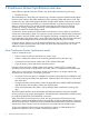
1 Continuous Access Synchronous overview Unless otherwise specified, the term P9000 in this guide refers to the following disk array: • P9500 Disk Array The GUI illustrations in this guide were created using a Windows computer with the Internet Explorer browser. Actual windows may differ depending on the operating system and browser used. GUI contents also vary with licensed program products, storage system models, and firmware versions.
Typical components A typical configuration consists of the following elements. Many, but not all, require user set up. • A P9500 system on the local side connected to a host. The system on the remote side, which may be a P9500 system, must be connected to the local array via Fibre Channel data paths. The secondary system may consist of a different models—XP12000 Disk Array/XP10000 Disk Array or of other vendors’ systems. • A host at the local site, connected to the local storage system.
Primary (MCU), secondary (RCU) systems The primary system manages the P-VOL and the following operations: • Host I/O operations to the P-VOL • Initial copy and update copy operations between the P-VOL and S-VOL • Pair status and configuration information The secondary system manages the S-VOL and the following operations: • Remote copy operations issued by the primary system • Assists in managing pair status and configuration (for example, rejects write I/Os to the S-VOL) The P9500 CU can function
for the S-VOL. Then, write I/O is allowed to the S-VOL while the pair is split. In this instance, S-VOL and P-VOL track maps keep track of differential data and are used to resynchronize the pair. Logical units on the local and remote systems must be defined and formatted prior to pairing. Data path Continuous Access Synchronous operations are carried out between local and remote systems connected by a Fibre Channel interface.
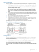
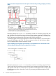
Figure 2 Creation and operation of Cnt Ac-S pairs and Cnt Ac-S Z pairs by specifying consistency group If the split command (Pairsplit-r or YKSUSPND) is issued to a consistency group of Cnt Ac-S pair, and if the I/O processing on some volumes in the consistency group has not finished, the split operation to the Cnt Ac-S volume pairs is executed for maintaining the data consistency after the I/O processing and the transfer of the data to the S-VOLs have finished.
The following figure shows the data in track 2 is copied to the R-VOL and the data in track 3 becomes differential data because track 2 is used for I/O processing of the volume in the consistency group when the split command is issued.
Table 2 Whether or not the host can access P-VOL/M-VOL when each option is specified (continued) Operation Option Whether or not the host can access P-VOL/M-VOL Business Continuity Manager Cnt Ac-S volume Cnt Ac-S Z volume Read Read Write Write Write access to P-VOL/M-VOL is prohibited. Y N Y N Write access to P-VOL/M-VOL is permitted.
Table 4 Status of Cnt Ac-S pairs and Cnt Ac-S Z pairs and the result when the pair splitting operation is performed (RAID Manager (RM)) Pair Status Cnt Ac-S Z pairs All pairs are in Duplex status Cnt Ac-S pairs There are pairs in both Duplex status and Suspend status All pairs are in Suspend status All pairs are in PAIR Cnt Ac-S pairs : PSUS status Cnt Ac-S Z pairs : Suspend Cnt Ac-S pairs : PSUS Cnt Ac-S pairs : PSUS Cnt Ac-S Z pairs : Suspend Cnt Ac-S Z pairs : Suspend There are pairs in both PA
To maintain pair consistency within the storage system, it is possible to do the following by using; • When creating a Cnt Ac-S pair with Remote Web Console, the created Cnt Ac-S pair can be registered in a specific consistency group automatically. If a Cnt Ac-S pair is suspended for any reason, all of the Continuous Access Synchronous P-VOLs registered in this specific consistency group will be suspended.
Figure 5 Remote copy operations Initial copy When a new pair is created, the entire contents of the P-VOL are copied to the S-VOL, cylinder by track (this does not include for diagnostic and unassigned alternate tracks). The initial copy synchronizes the P-VOL and S-VOL, independently of host I/O processes. In an initial copy, you can elect to have no data copied if the P-VOL and S-VOL are already identical.
2 Requirements and specifications This chapter provides basic system requirements. In addition to the information in this section, “Planning for Continuous Access Synchronous” (page 18) provides many specifications, recommendations, and restrictions for the elements of a Continuous Access Synchronous system that require attention before setting up and using Continuous Access Synchronous.
Table 6 General system requirements (continued) Item Requirement Supported host platforms • HP-UX • IBM AIX • Red Hat Linux • Oracle Solaris • Windows server 2003 • Windows Server 2008 • VMware ESX Contact your HP account team for the latest information. Data path • 8 paths at maximum, from MCU to RCU. • Fibre Channel, direct or with switch connections. See “Planning data paths” (page 25). Logical paths • Maximum of eight from primary system to secondary system.
3 Planning for Continuous Access Synchronous This chapter provides information and instructions for planning primary and secondary systems, pair volumes, data paths, and the other elements. Preparing P9500 systems The following preparations are required for the storage systems in a Continuous Access Synchronous pair relationship: • Remote Web Console must be LAN-attached to the primary and secondary systems. See the HP P9000 Remote Web Console User Guide for information.
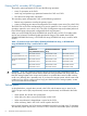
serial number. It is possible that a serial number overlap could occur. If you have two systems with the same serial number, contact HP Technical Support for assistance. • When you connect the storage systems with the following combinations, the range you can specify for each model is restricted. P9500 Disk Array and XP12000 Disk Array ◦ When you connect P9500 Disk Array and XP12000 Disk Array, you may specify the range as shown in the following table.
Planning volume pairs To plan Continuous Access Synchronous pair volumes, you need to do the following: • At the local site, identify the volumes that contain important data to be backed up. • At the remote site, set up the volumes that will hold the copied data. Volume pair requirements and recommendations The following requirements and information are provided to help you prepare Continuous Access Synchronous volumes: • A volume can only be assigned to one Continuous Access Synchronous pair.
• When creating multiple pairs concurrently, make sure that you set up S-VOL LUNs in a way that allows the system to correctly match them to your selected P-VOLs. Even though you select multiple volumes as P-VOLs in the Remote Web Console Pair create procedure, only one of them displays in the dialog box—the one with the lowest LUN. Because of this, you are able to specify only one S-VOL. The system automatically assigns LUs on the secondary system as S-VOLs for the other selected P-VOLs according to LUN.
When you start the initial copy, you will specify whether to manage differential data by Tracks or Cylinders. In Remote Web Console, you also have the Auto option. With Auto, either Cylinder or Track is used, depending on the basic size of the LU. • When creating a pair with RAID Manager, the Auto option is not available. If you do not specify anything, Track is used. • If VLL is used, the number of cylinders that you set with VLL software is used to determine the Auto setting.
Use the following formula. The ceil()value between the parentheses should be rounded up to the nearest integer. LBA = Logical Block Address. The "Max. LBA" indicates the capacity of a volume and is measured in blocks. For OPEN-3, OPEN-8, OPEN-9, OPEN-E, OPEN-L, OPEN-K: The number of cylinders = ceil(ceil(Max. LBA/96)/15)+1 For OPEN-V: The number of cylinders = ceil(ceil(Max.
Table 9 Priority set for P-VOLs for which initial copy operation is performed P-VOL Value set for Priority LUN 00 2 LUN 01 3 LUN 02 1 LUN 03 4 The order of starting initial copy and the Priority which is set for the P-VOLs are shown in the following table.
Table 12 Order of starting initial copy being performed (continued) Order of starting initial copy P-VOL Value set for Priority Remarks 5 LUN 11 1 Continuous Access Synchronous pair for which initial copy is newly instructed to be performed 6 LUN 10 2 Continuous Access Synchronous pair for which initial copy is newly instructed to be performed The Priority is determined within the range of the number of initial copy operations performed at the same time.
Table 13 Link speed, maximum distance to 10 km (continued) Link speed Maximum distance for best performance 4 Gbps 3 km 8 Gbps 1.5 km Your HP account team can provide the latest information on the availability of serial-channel Continuous Access Synchronous connections. Supported data path configurations Three Fibre Channel configurations are supported for Continuous Access Synchronous. LUN Manager is used to set port topology.
Set port topology to the following: NL/FL port: Fab on, FC-AL F port: Fab on, Point-to-Point • Best practice is to create at least two independent data paths (one per cluster) between the primary and secondary systems for hardware redundancy for this critical element. • When 4,000 pairs or more are used, we recommend that you restrict the number of pairs when creating pairs, so that 4,000 pairs or less use one physical path, to distribute load on the physical path.
Port requirements Ports set up for Continuous Access Synchronous operations have the following maximum and minimum requirements: • One initiator port can be connected to a maximum of 64 RCU target ports. • One secondary system port can be connected to a maximum of 16 ports on a primary system. The number of logical paths that can be specified does not depend on the number of ports configured for Continuous Access Synchronous.
2. Create the pair or pairs and assign them to consistency group 127. • In RAID Manager, assign the pair or pairs to this group number when you create the pairs. • In Remote Web Console, the pair or pairs are automatically assigned to consistency group 127 when function switch 30 is On and the pair or pairs are created.
• In a bidirectional configuration, if all data paths for the primary system of the reverse direction pair are disconnected when-pair status is changing to PSUE, the disconnection may not be detected. • If all the data paths for Continuous Access Synchronous pairs are disconnected, but the paths used for Cnt Ac-J pairs are connected, failure suspend does not occur and S-VOLs cannot be changed to PSUE status.
4 Sharing Continuous Access Synchronous volumes This chapter helps you plan Continuous Access Synchronous pair volumes when they are shared with non-Continuous Access Synchronous volumes. It discusses the program products that can be used with Continuous Access Synchronous. Volume types that can be shared with Continuous Access Synchronous The following table indicates whether non-Continuous Access Synchronous volumes can also be used as Continuous Access Synchronous P-VOLs and S-VOLs.
Table 14 Volume types that can be shared with Continuous Access Synchronous (continued) Volume type Used as P-VOL? Used as S-VOL? S-VOL in PAIR status No No S-VOL in PSUS (Delete pair to RCU) status Yes No S-VOL in SSWS status Yes No S-VOL in PSUE (pair suspended-error) status Yes No Volume with Read/Write attribute Yes Yes Volume with Read Only attribute Yes Yes Volume with Protect attribute Yes Yes Volume that is disabled for use as an S-VOL Yes No No No Yes Yes Yes Yes Vo
Continuous Access Journal S-VOL is asynchronous, and the secondary system can be located much greater distances from the local and remote Continuous Access Synchronous sites. Creating both a Continuous Access Synchronous and a Continuous Access Journal backup insures that a copy in a third location is available in the event that the primary site or one of the systems fails.
Figure 10 Shared Cnt Ac-S S-VOL with BC P-VOL 3. In the following figure, the configurations shown in the first two figures in this section are combined. Both the Continuous Access Synchronous P-VOL and S-VOL function as Business Copy P-VOLs, providing multiple copies at the local and remote sites. Figure 11 Shared Cnt Ac-S P-VOL, S-VOL with multiple BC P-VOLs Configurations with Business Copy S-VOLs In the following figure, a Business Copy S-VOL also functions as a Continuous Access Synchronous P-VOL.
Table 15 Pair status reporting (continued) Number of Cnt Ac-S pairs Number of BC S-VOLs Pair status 1 0 Continuous Access Synchronous pair status 1 1 Continuous Access Synchronous pair status 1 2 or more Continuous Access Synchronous pair status The following table indicates when data is current on a shared Continuous Access Synchronous/Business Copy volume based on the pair statuses.
LUN Manager • LUN Manager operations do not affect Continuous Access Synchronous operations. • Volumes that are under secure ports and/or that are assigned to host groups can also be assigned to Continuous Access Synchronous pairs. • Volumes that are assigned to Continuous Access Synchronous pairs can also be assigned to secure ports and host groups for LUN Manager. • Continuous Access Synchronous S-VOLs cannot be accessed by any UNIX/PC server host except when the pair is split.
3. 4. 5. After you have disabled LDEV data collection and/or disconnected Performance Monitor wherever possible, then connect to the storage system using Remote Web Console and launch Continuous Access Synchronous. When Continuous Access Synchronous operations are completed, exit Continuous Access Synchronous and Remote Web Console. Re-enable Performance Monitor data collection. For further information on Performance Monitor, see the HP P9000 Performance for Open and Mainframe Systems User Guide.
Table 18 Status, availability of DRU operation (continued) Continuous Access Synchronous volume S-VOL Pair status Changing access attribute Referencing access attribute PSUS Yes Yes PSUE Yes Yes SMPL Yes Yes COPY No Yes PAIR No Yes PSUS No* Yes PSUE No Yes * If the S-VOL Write option is enabled, the access attribute can be changed. The following table indicates whether a DRU volume with the specified access attribute can be used as a Continuous Access Synchronous P-VOL or S-VOL.
(3390-A) as the S-VOL is available. However, the swap operation to the reversed combination of the V-VOL (3390-A) or not-V-VOL (3390-A) as the P-VOL and the not-V-VOL (3390-X) as the S-VOL is not available. Note The following items indicate the note to use the V-VOL as a part of Cnt Ac-S Z pair.
5 Configuration operations This chapter provides instructions for setting up a Continuous Access Synchronous system that is ready for pair operations. Configuration workflow 1. 2. 3. 4. 5. Check prerequisites for each procedure. In the production system, identify the production volume or volumes that will become Continuous Access Synchronous P-VOLs. In the remote backup system, create the volumes that will become the S-VOLs.
3. In the Switch Display box, select Port. The ports associated with the local storage system are listed. 4. Right-click the port that you want to configure and select the desired port type (Initiator, RCU Target, or Target). When you have modified all the ports you want, review the Preview list. 5. 6. • To change the attribute that you set for a port, right-click the port in the full upper list and select the new attribute.
1. On the menu bar, click Actions > Remote Copy > Continuous Access Synchronous > RCU Operation. The RCU Operation window opens. 2. 3. Change to Modify mode by clicking the icon. In the Display box, select MCU&RCU. The tree displays CUs for the accessed system. 4. Click the desired CU in the tree. You must add RCUs to each CU separately. For ESAM, select CU Free (do not select a specific CU number). 5. Right-click the list area on the right-side.
• 6. When CU Free is selected In the RCU S/N box, enter the remote CU’s 5-digit serial number.
NOTE: Enter the lower 5-digit number displayed on the Remote Web Console main window as the Serial Number. 7. 8. In the Controller ID box, select the remote system’s controller ID. In the Logical Adr. (RCU CU) box (appears when specific CU selected - not CU Free), enter the CU number of the RCU being added. The CU number differs by the specified controller ID, as follows: • When the specified controller ID is 6 (P9500) or 5 (XP24000/XP20000 Disk Array), you can select a CU number from 00 to FE.
14. In the RIO MIH Time (sec.) box, enter the amount of time that can pass before the system stops the copy operation as failed. RIO MIH means “remote I/O missing interrupt handler.” The range of time is from 10 seconds to 100 seconds. The default is 15 seconds. 15. In the Round Trip Time (ms) box, enter the time limit for data to travel from the P-VOL to the S-VOL. This value is used by the system to control initial copy pace when update copying is in progress.
Table 21 Initial copy pace used for response time calculation Interface Initial Copy Only in Progress Initial, Update Copy in Progress RAID Manager User-specified value User-specified value between 1 and 8 8 Remote Web Console User-specified value User-specified value between 1 and 8 8 When Initial Copy Pace specified When Initial Copy Pace specified at the Time of Pair Creation is 1 at the Time of Pair Creation is 9 to 8 to 15 Table 22 Sample settings Round Trip Time between MCU RCU[ms] Line S
6. In the M-R Path box, define the logical path between local and remote systems: 1. In the Port column, select a local system initiator port. 2. In the Pair-Port column, select the remote system RCU target port. This establishes a logical path with the selected initiator port. You can abbreviate the number to two characters. For example, “1A” can be entered instead of “CL1-A”. Letters may be uppercase or lowercase. 7. 8. 9. When you have entered the desired logical paths, click Set.
5. 6. 7. In the Maximum Initial Copy Activities box, enter the number of volumes that you want to be copied concurrently during an initial copy or resync operation. The number can range from 1 to 512 volumes. The default is 64 volumes. • This setting may impact the performance of the primary system. This depends on this setting and the amount of I/O activity. Using the default limits the impact on performance.
6 Pair operations This chapter provides prerequisite information and instructions for performing Continuous Access Synchronous operations. Pair operations workflow Basic Continuous Access Synchronous operations follow: 1. Check prerequisites for each procedure. 2. Always check pair status. Each Continuous Access Synchronous operation requires the pair to be in a specific status. 3. Create the pair, in which the S-VOL becomes a duplicate of the P-VOL. 4.
The P-VOL Fence Level setting, which you specify during the Paircreate operation, determines whether the host is denied access or continues to access the P-VOL when a Continuous Access Synchronous pair is suspended due to an error. You will select one of the following Fence Level settings: • Data: the P-VOL is fenced if an update copy operation fails. “Data” ensures that the S-VOL remains identical to the P-VOL. This is done by preventing the host from writing to the P-VOL during a failure.
8. 9. From the P-VOL Fence Level list, select the fence level for the new P-VOL(s). The fence level determines the conditions under which the primary system rejects write operations to the P-VOL. For an explanation of the options, see “Change fence level” (page 54). In the Initial Copy list, select one of the following: • Entire Volume: to create the Continuous Access Synchronous pair relationship and copy the data from primary to secondary volumes immediately.
• You can set an option to block updates to the P-VOL while the pair is split. This results in the P-VOL and S-VOL staying synchronized. • Another option is to enable I/O to the S-VOL from a host. The secondary system records the updated tracks as differential data. When the pair is resynchronized, the secondary system sends the differential data to the primary system which merges all differential data to determine which tracks are out-of-sync. Prerequisite information The pair must be in PAIR status.
When resynchronizing, Continuous Access Synchronous pairs can be migrated to External Storage Access Manager. To migrate Continuous Access Synchronous pairs to ESAM pairs, see the HP P9000 External Storage Access Manager User Guide. Procedure 7 To resynchronize a pair 1. On the menu bar, click Actions > Remote Copy > Continuous Access Synchronous > Pair Operation. The Pair Operation window opens. 2. 3. 4. Change to Modify mode by clicking the icon.
4. 5. 6. In the list, select the pair volume that you want to want to release, right-click, and select Pairsplit-S from the menu. The Pairsplit-S dialog box displays. From the Delete Pair by Force list, select one of the following: • Yes, to forcibly delete the pair or pairs, even when the primary system is unable to communicate with the secondary system. Specifying Force allows host operations to continue.
7 Monitoring and maintenance This chapter provides information and instructions for monitoring and maintaining the Continuous Access Synchronous system. Monitor pair status Monitoring the Continuous Access Synchronous system is an ongoing operation that should be performed frequently to keep track of and maintain your pairs. • When you want to perform a pair command, first check the pair’s status. Each operation requires a specific status or set of statuses.
Pair status definitions Status descriptions are provided in the table below. Click File/Refresh to make sure the data is current. Table 23 Pair status definitions Status Description Access to P-VOL Access to S-VOL SMPL This volume is not currently assigned to a Continuous Read/write Access Synchronous pair. Read/write COPY The initial copy operation for this pair is in progress. Read/write This pair is not yet synchronized.
Split and suspend types This section discusses pairs that are split by the user (PSUS), and pairs that are suspended by the system (PSUE). • • You can split a pair when the initial copy operation is complete. ◦ You must split a pair must be to perform media maintenance on the P-VOL or to access the S-VOL (when S-VOL write is enabled). ◦ When you split a pair, the primary system ensures synchronization by completing any pending update copy operation before changing the status to PSUS.
System behavior Note the following behaviors for suspended pairs: • The primary system stops performing update operations to the S-VOL. It may or may not continue accepting write I/Os to the P-VOL depending on the P-VOL fence level setting. • If an update fails, the primary system maintains exact synchronization by reporting a unit check and de-committing the P-VOL update. This ensures that both the host system and application program regard the write operation to the P-VOL as failed.
Procedure 11 To export pair information to a text file 1. On the menu bar, click Actions > Remote Copy > Continuous Access Synchronous > Pair Operation. The Pair Operation window opens. 2. 3. Change to Modify mode by clicking the icon. In the Pair Operation window, click Display Filter, select the information that you want to export, and click Set. The Pair Operation window redisplays with the filtered columns displayed. Click Export.
Table 25 Usage Monitor fields (continued) Item Description Update The most recent data sample time on the graph. Usage Monitor Graph Remote I/O statistics and status of remote copy monitor. Select data to be graphed The usage monitor graph plots the I/O data that you specify. On the graph: • The X-axis indicates time. • The Y-axis indicates the number of I/Os during the sampling period. • The legend on the right side shows the data being displayed.
Table 26 Remote copy I/O statistics data (continued) Data type Description Average Transfer Rate Average transfer rate for initial remote I/Os (kB/sec) Average response Average response time (msec) for initial copy remote I/Os Update Copy Update copy RIO count Number of update copy remote I/Os Average transfer rate Average transfer rate (kB/sec) Average response Average response time (msec) for update copy remote I/Os Synchronization [2] Pair Synchronized For initial copy operations, the percen
Table 27 Logical path status definitions (continued) Status Description Serial Number Mismatch The serial number of the control unit that is connected to this logical path does not match the serial number specified by the Add RCU dialog box. Invalid Port Mode The specified port does not have the initiator attribute. RCU Port Number Mismatch There are three possible causes: • The specified port in the secondary system is physically disconnected from the primary system.
RCU maintenance Change minimum paths, round trip time, other RCU options You can change the options that affect how the system runs your copy operations. These are: • Number of minimum paths for a pair • Wait time until data transfer is complete (MIH RIO) • Round trip time, which affects update and initial copy priorities Procedure 15 To change the RCU options 1. On the menu bar, click Actions > Remote Copy > Continuous Access Synchronous > RCU Operation. The RCU Operation window opens. 2. 3. 4. 5.
Delete Continuous Access Synchronous You can delete the Continuous Access Synchronous relationship between the primary and secondary systems. Prerequisite information • All Continuous Access Synchronous pairs must be deleted. • All logical paths will be deleted when the relationship is deleted. • Deleting the Continuous Access Synchronous relationship with a remote system does not affect the Continuous Access Synchronous operations between other primary system CUs and that secondary system.
system changes the P-VOL status to suspended-by RCU but cannot change the status of the S-VOLs. • If a primary or secondary system is powered off and the backup batteries are fully discharged while Continuous Access Synchronous pairs are suspended, differential data is retained to SSD. In this unlikely case, MCU copies differential data to RCU when the pairs are resynchronized. Planned outage of the primary system A planned outage of the primary system does not affect Continuous Access Synchronous.
Media maintenance A pair must be suspended before performing media maintenance on the P-VOL. Write operations to the P-VOL that specify normal authorization are duplicated on the S-VOL. Write operations with diagnostic or device support authorization are completed at the P-VOL only.
8 Data migration This chapter discusses using Continuous Access Synchronous to migrate data from one storage system to another. Migrate data Continuous Access Synchronous can be used to move data from one system to another.
9 Planning and procedures for disaster recovery This chapter discusses and provides instructions for using Continuous Access Synchronous for disaster recovery. Disaster recovery overview The major steps in preparing for disaster recovery are: 1. Identify the volumes and groups that contain important files and data for disaster recovery. 2.
3. 4. (for example, database log files). These S-VOLs should be recovered using files that you have confirmed to be current. Perform file recovery as needed. At the secondary site, connect to each remote system and release all Continuous Access Synchronous pairs. When an S-VOL changes to simplex, you cannot distinguish it from a non-Continuous Access Synchronous simplex volume. If necessary, use the volume manager to change the volume labels of the S-VOLs. 5. 6. 7. Complete file recovery procedures.
Transfer operations back to the primary site When host operations are running at the secondary site, the primary site should be restored and operations transferred back. In the following procedure, you will establish Continuous Access Synchronous pairs at the secondary site, with data flow moving from the secondary site to the local.
12. At the primary site, establish consistency groups and create the Continuous Access Synchronous pairs in the original direction. You may use the "none" initial copy option because all P-VOLs and S-VOLs are synchronized. If there is any possibility that the volumes are not 100% synchronized, use the Entire Volume initial copy option to be safe. 13. Vary the primary system and P-VOLs online, and start the host operations.
10 Troubleshooting This chapter provides troubleshooting information. General troubleshooting General troubleshooting consists of the following kinds of errors and problems: • General errors with corrective actions • CU Path Status Problems • Split Pairs Table 29 General troubleshooting Error Corrective action The Remote Web Console computer hangs, or Continuous Access Synchronous operations do not function properly.
Table 29 General troubleshooting (continued) Error Corrective action The paircreate or pairresync operation resulted in a timeout error. • Hardware failure: If the timeout error was caused by a hardware failure, a SIM is generated. If this occurs, call service personnel, then retry Continuous Access Synchronous operations after the problem is fixed. • Heavy workload: If no SIM was generated, wait 5 or 6 minutes then check the pair’s status.
Table 30 Troubleshooting secondary path status problems (continued) Path status Description resources in the two systems are being used for other connections. Serial Number Mismatch The primary system’s S/N does not match the specified S/N. Corrective action of four secondary systems with up to eight paths to each system. • Make sure that all primary and secondary system ports are properly configured: ordinary RCU target ports for secondary systems initiator ports for primary systems.
Table 30 Troubleshooting secondary path status problems (continued) Path status Description Corrective action Logical Blockade The primary system port does Repair the port on the primary system. not work. secondary system port does not work. Repair the port on the secondary system. Delete the path with Edit Path or Delete RCU, then add the path again with Edit Path or Add RCU. The path relay equipment does not work. Repair the path relay equipment.
Error codes and messages Remote Web Console displays error messages when error conditions occur during Continuous Access Synchronous operations. The error message describes the error and provides a part code and error code. The error message may also include a P9500 error code. You may need to call HP Technical Support for assistance. Report the error code(s). See the HP P9000 Remote Web Console Messages for a list of the error codes.
Table 32 RAID Manager error codes for Continuous Access Synchronous (SSB1 is B901/B90A/B90B/B912/D004) (continued) Error code Description (SSB2) B97C The command was rejected because the volume status is SMPL. B990 The pair cannot be created because the consistency group number is greater than is allowed. If this error occurred when you did not specify the consistency group number, contact HP Technical Support.
Table 32 RAID Manager error codes for Continuous Access Synchronous (SSB1 is B901/B90A/B90B/B912/D004) (continued) Error code Description (SSB2) C233 The command was rejected because the S-VOL status is SMPL. C234/C235/ C236/C237 The command was rejected because an internal logical error has occurred. C238 The command was rejected because the specified volume is the volume other than P-VOL.
Table 32 RAID Manager error codes for Continuous Access Synchronous (SSB1 is B901/B90A/B90B/B912/D004) (continued) Error code Description (SSB2) C316 The P-VOL is in process of drive copy for failure assistance. C317 The P-VOL is in process of drive copy for an SVP request. C318 The P-VOL is terminating the copy task. C319 The P-VOL is in process of collection copy. C31A The P-VOL is in process of collection access. C31B The P-VOL is blocked.
Table 32 RAID Manager error codes for Continuous Access Synchronous (SSB1 is B901/B90A/B90B/B912/D004) (continued) Error code Description (SSB2) C33E The pair cannot be created because the S-VOL is not implemented or is blocked (DEV NOT READY status). C33F The corresponding volume cannot be specified as an S-VOL because the volume is already specified as Continuous Access Synchronous pair volume. C35C The P-VOL is not accessible.
Table 32 RAID Manager error codes for Continuous Access Synchronous (SSB1 is B901/B90A/B90B/B912/D004) (continued) Error code Description (SSB2) C3B1 The number of paths is smaller than the required minimum number of paths. C3B6 The True Copy P-VOL is a Business Copy volume. C3B7 The True Copy S-VOL is a Business Copy volume. C3BA A request for a Paircreate operation was received.
Table 32 RAID Manager error codes for Continuous Access Synchronous (SSB1 is B901/B90A/B90B/B912/D004) (continued) Error code Description (SSB2) CB21 In a Pairresync operation, all difference setting was abnormally terminated. CB5E When connected to the old model, LUSE pairs with different amounts of capacity cannot be created. CB5F If the path is set between CUs LUSE pairs with different CUs cannot be created. CB60 Continuous Access Synchronous is not installed in the secondary system.
Table 32 RAID Manager error codes for Continuous Access Synchronous (SSB1 is B901/B90A/B90B/B912/D004) (continued) Error code Description (SSB2) CBED A request for a Paircreate operation was received. The command was rejected because the specified S-VOL was a Continuous Access Journal S-VOL or journal volume. CBEE A request for a Paircreate was received. The command was rejected because the specified P-VOL was already created as a Continuous Access Journal pair for differential resync.
11 Support and other resources Contacting HP For worldwide technical support information, see the HP support website: http://www.hp.
In the Storage section, click Disk Storage Systems for hardware or Storage Software for software, and then select your product. HP websites For additional information, see the following HP websites: • http://www.hp.com • http://www.hp.com/go/storage • http://www.hp.com/service_locator • http://www.hp.com/support/manuals • http://www.hp.com/support/downloads • http://www.hp.
Table 34 Document conventions (continued) Convention Element Monospace text • File and directory names • System output • Code • Commands, their arguments, and argument values Monospace, italic text • Code variables • Command variables Monospace, bold text WARNING! CAUTION: IMPORTANT: NOTE: TIP: 86 Emphasized monospace text Indicates that failure to follow directions could result in bodily harm or death. Indicates that failure to follow directions could result in damage to equipment or data.
A Continuous Access Synchronous GUI reference This appendix describes the Continuous Access Synchronous windows, dialog boxes, fields, and behaviors in Remote Web Console. Continuous Access Synchronous windows Continuous Access Synchronous information and pair operations are seen and initiated in the following GUI windows: • Pair Operation • RCU Operation • Usage Monitor • History • System Option Menu commands for the pair operations that you can perform in the windows.
Window Context menu command Description RCU Operation window RCU Status Displays secondary systemstatus and path status. RCU Operation > Add RCU Used to add a secondary system to the primary system in a Continuous Access Synchronous relationship. RCU Operation > Change RCU Option Used to change secondary system options. RCU Operation > Delete RCU Used to delete a secondary system. Edit SSID(s) & Path(s) > Add Path Used to add paths to existing secondary systems.
Use this window to: • “Create pairs” (page 49) • “Split pairs” (page 51) • “Resynchronize pairs” (page 52) • “Release pairs” (page 53) • “Check pair status” (page 49) • “Change fence level” (page 54) Item Description Tree Displays the connected storage system, the LDKC, the CU grouping, the CUs, ports, and host groups. Select the desired CU grouping, CU ( ), port ( ), or host group to display related LUs. Only one CU grouping, CU, port, or host group can be selected.
Item Description : PSUS. The pair has been split by the user (pairsplit-r), or the pair has been released by the user from the RCU (pairsplit-S). The volumes in this pair are not synchronized. : SSWS. This is specific to the ESAM pair. : PDUB. This Continuous Access Synchronous LUSE pair is in the COPY or PAIR state, but at least one LDEV pair within the Continuous Access Synchronous LUSE pair is in the SMPL or PSUE state.
Detailed Information dialog box This dialog box lets you view details for a selected Continuous Access Synchronous pair. Item Description P-VOL and S-VOL areas The following displays in the order shown: • Port - GID – LUN LDKC number: CU number: LDEV number). • Emulation type • Capacity in MB (to two decimal places). • The number of blocks CLPR Local volume’s cache logical partition number and name. Group Name Local volume’s host group name. Pair Status Status of the pair’s local volume.
Item Description Update Type Program product pair type (Continuous Access Synchronous). Copy Pace Number of tracks copied per interval during the initial copy. Copy pace can be between 1-15 tracks. This field displays only when the P-VOL is selected. It is disabled when the status becomes PAIR. Initial Copy Priority Order in which initial copy/resynchronizing operations are performed on multiple pairs. This field displays only when the P-VOL is selected. It is disabled when the status becomes PAIR.
Paircreate dialog box This dialog box lets you create a pair. See “Create pairs” (page 49) for complete information. Item Description P-VOL Shows the P-VOL port, GID, LUN (LDKC number, CU number, LDEV number), and CLPR number and name. S-VOL Where the S-VOL is defined: port, GID, LUN. RCU Where the secondary system is defined. • For CU Free: The serial number, LDKC number, Controller ID, model name, Path Group ID, and Path type.
Pairsplit-r dialog box This dialog box lets you split a pair. See “Split pairs” (page 51) for complete information. Item Description Volume Shows the selected volume’s port, GID, LUN (LDKC number, CU number, LDEV number). S-VOL Write Where the option is defined that allows write I/O to the S-VOL when the pair is split. Options are Enable and Disable. Suspend Kind Where the option is defined that allows write I/O to the P-VOL when the pair is split.
This dialog box lets you resynchronize a pair. See “Resynchronize pairs” (page 52) for complete information. Item Description P-VOL Shows the selected volume’s port, GID, LUN (LDKC number, CU number, LDEV number). P-VOL Fence Level Where the option is defined for rejecting write operations to the P-VOL. Copy Pace Where maximum number of tracks to be copied is defined: 1-15. Priority Where the order is defined for the current pair to be created. Options are from 1 to 256.
This dialog box lets you change the P-VOL Fence Level for an existing pair. See “Change fence level” (page 54) for complete information. Item Description Volume Shows the selected volume’s port, GID, LUN (LDKC number, CU number, LDEV number). P-VOL Fence Level Where the option is defined for rejecting write operations to the P-VOL. Display Filter dialog box This dialog box lets you filter the information displayed on the Pair Operation window. Filters are determined by the tree selection.
Item Description P-VOL/S-VOL Select the volume type, P-VOL or S-VOL or all types. CT Group Select the consistency group. MCU-RCU Path Select path type (disabled at this time). CLPR Select the CLPR (cache logical partition). Internal/External VOL Select the volume type, internal or external, or all types. Quorum Disk ID Select the quorum disk ID. VOL Access Select the access status of the quorum disk.
• “Monitor, maintain logical paths” (page 61) • View the following: ◦ Information related to Continuous Access Synchronous storage systems: “RCU Operations list when “MCU&RCU” is selected ” (page 99) ◦ Information related to ports in: “RCU Operations list when “Port” is selected ” (page 100) Item Description Tree Display allows you to select either MCU&RCU display (default) or Port display for the RCU Operation window.
RCU Operations list when “MCU&RCU” is selected List field descriptions when MCU&RCU is selected in the Display box are shown below. The fields vary according to the selections you make in the tree: • “When LDKC, a CU group, or CU is selected in tree” (page 99) • “When an MCU or RCU is selected in tree” (page 100) When LDKC, a CU group, or CU is selected in tree The following columns appear in the list area when MCU&RCU is selected in Display, and an LDKC, CU group, or CU is selected in the tree.
Item Description Status • Normal indicates no path failure to the RCU. • Failed indicates a failure in all paths to the RCUs. • Warning indicates that a failed path to the RCU exists. • The field is empty when the local CU is an MCU. Num. of Path Number of paths (blank when the connected CU is an MCU). When an MCU or RCU is selected in tree The following columns appear in the list area when MCU&RCU is selected in Display, and an MCU or an RCU is selected in the tree.
RCU Status dialog box • When a specific CU is selected • When CU Free is selected RCU Status dialog box 101
This dialog box lets you view status and other information for the selected RCU. Right-click an RCU (MCU&RCU in Display), then select RCU Status. Item Description List Paths on this system. • No. The paths are listed in numbered order. • Path Status. The path’s condition. See “Logical path status definitions” (page 61) for definitions. • MCU Port. Port number of the MCU. • RCU Port. Port number of the RCU. RCU S/N Serial number of the RCU.
Item Description Round Trip Time The time limit for data to travel from P-VOL to S-VOL. Check box, "Refresh the To refresh the RCU Operation window after closing the RCU Status dialog box, click the RCU Operation window check box. By default, the check box is not selected.
This dialog box lets you link two storage systems for creating Continuous Access Synchronous pairs. See “Configure storage systems, define logical paths” (page 41) for complete information. Item Description RCU S/N Remote system’s CU serial number. LDKC Remote system’s LDKC number. Controller ID Remote system’s controller ID. Logical Adr. (RCU CU) Remote system’s CU number. SSID Remote system’s SSID. Path Gr. ID Remote system’s Path group ID.
This dialog box lets you change data path parameters: the minimum number of paths, RIO MIH, and Round Trip Time options. See “Configure storage systems, define logical paths” (page 41) for complete information. Item Description Minimum Paths Where minimum number of paths is defined. RIO MIH Time (sec.) Where the time is defined in which the copy operation must complete, otherwise the operation fails. Options are 10 to 100 seconds.
This dialog box lets you add an SSID. See “Add, delete SSIDs for an RCU” (page 63) for complete information. Item Description SSID (1st) Existing SSID. SSID (2nd), (3rd), (4th) Where additional SSIDs are defined. Usage Monitor window This window lets you monitor and use copy-operations data and I/O statistics. See “Monitor copy operations, I/O ” (page 59) for complete information. Item Description Monitoring Switch • Enable: Monitoring is on. Graph displays. • Disable: Monitoring is off.
History window This window lets you view the history of operations performed on pairs, and the data associated with each operation. Information about field behavior is shown in “History window notes” (page 108). Field Description Status • The current status of operation history: • No history file exists: Operation history does not exist. • Reading a history file failed: An attempt to read operation history failed. • Updating ...
Field Description ◦ Pair Resync. Start : Pair resync operation started. ◦ Pair Resync. Complete : Pair resync operation completed. • VOL : LDKC number, CU number, and LDEV number of the local volume. • Paired VOL : LDKC number, CU number, and LDEV number of the paired volume. • Copy Time : Amount of time for the operation. Displayed only for Pairing Complete and Pair Resync. Complete.
System Option window This window lets you change the number of volumes on which the initial copy operation is performed concurrently. Field Description Tree Provides access to the subsystem. Select Subsystem. Activities List The system option. See “Set number of volumes to be copied concurrently, path watch time” (page 47) Preview List When you change settings in the System Operation window, the Preview list shows the changes. Here, the changes have not been applied to the storage system.
Glossary array group A group of four or eight physical hard disk drives (HDDs) installed in a P9000 or XP disk array and assigned a common RAID level. RAID1 array groups consist of four (2D+2D) or eight HDDs (4D+4D). RAID5 array groups include a parity disk, but also consist of four (3D+1P) or eight HDDs (7D+1P). All RAID6 array groups are made up of eight HDDs (6D+2P). This is also known as a parity group or a RAID group. BC P9000 or XP Business Copy.
parity group A set of hard disk drives that have the same capacity and that are treated as one group. A parity group contains both user data and parity information, which enables user data to be accessed if one or more drives in the group is not available. PDU Power distribution unit. The rack device that distributes conditioned AC or DC power within a rack. port A physical connection that allows data to pass between a host and the disk array.
Index A Add Path dialog box, 105 Add RCU dialog box, 104 Add SSID dialog box, 106 B G graphing I/O data, 60 bandwidth, 25 bitmap areas, 23 C cache memory changes, and pair status, 18 cache, planning considerations, 18 Change Pair Option dialog box, 96 consistency groups keeping status consistent, 28 planning, 28 requirements, 28 split/suspend behaviors with, 30 contacting HP, 84 conventions document, 85 storage capacity values, 85 text symbols, 86 creating pairs, 49 D data path description, 9 planning,
duplicate volumes and hosts, 21 exporting pair details, 58 general information, 8 planning, 20 releasing, 53 requirements, recommendations, 20 resynchronizing (resuming), 52 splitting, 51 Pairsplit-r dialog box, 94 Pairsplit-S dialog box, 95 paths, changing minimum number of, 63 performance, planning for, 19 ports defining attributes, 40 planning, 27 requirements, 28 power-off, managing, 64 PSUS types, 57 R service locator website, 85 text symbols, 86 transfer operations to local site, 70 typographic conv