HP P9000 Continuous Access Journal User Guide Abstract This guide explains how to use HP P9000 Continuous Access Journal Software to replicate data between local and remote HP P9000 disk arrays and to achieve disaster tolerance with maximum application performance. Topics include setting up remote copy connections, configuring the storage system, creating and monitoring remote copies, recovering from a disaster, and troubleshooting.
© Copyright 2010, 2011 Hewlett-Packard Development Company, L.P. Confidential computer software. Valid license from HP required for possession, use or copying. Consistent with FAR 12.211 and 12.212, Commercial Computer Software, Computer Software Documentation, and Technical Data for Commercial Items are licensed to the U.S. Government under vendor's standard commercial license. The information contained herein is subject to change without notice.
Contents 1 Continuous Access Journal overview ............................................................8 Continuous Access Journal software ...........................................................................................8 How Continuous Access Journal works........................................................................................8 Hardware and software components...........................................................................................9 P9500 storage systems.....
Sizing bandwidth ..................................................................................................................35 Five sizing strategies ..........................................................................................................35 Calculating bandwidth ......................................................................................................36 Sizing bandwidth for peak write-workload........................................................................
Delete logical paths ..........................................................................................................88 Delete the logical path between primary and secondary storage system ...................................89 Manage power-off for systems and network devices ...................................................................89 When power stops unexpectedly.........................................................................................
LUN Manager......................................................................................................................128 Thin Provisioning .................................................................................................................128 Data Retention ....................................................................................................................128 Performance Monitor .........................................................................................
Logical Path Information....................................................................................................172 Port Information for the local system....................................................................................173 DKC Status dialog box ....................................................................................................173 Add DKC dialog box .......................................................................................................
1 Continuous Access Journal overview Unless otherwise specified, the term P9000 in this guide refers to the following disk array: • P9500 Disk Array The GUI illustrations in this guide were created using a Windows computer with the Internet Explorer browser. Actual windows may differ depending on the operating system and browser used. GUI contents also vary with licensed program products, storage system models, and firmware versions.
Remote replication occurs using journal volumes on the local and remote systems. • The journal on the local system is the “master journal”. • The journal on the remote system is the “restore journal”. Replication occurs in the following sequence: • • • Journal obtain - When the host sends an update to the primary volume, the system’s journal-obtain function triggers a copy of the update data to the master journal volume. ◦ The host assigns write-sequence numbers to the data sent to the journal.
A Continuous Access Journal system consists of the following: • P-VOLs and S-VOLs on the local and remote P9500 • Master and restore journal volumes on the local and remote P9500 • Master and restore journals on the local and remote P9500 ◦ The master journal consists of the primary volume(s) and master journal volume(s). ◦ The restore journal consists of the secondary volume(s) and restore journal volume(s).
MCUs control the primary storage volume (P-VOL) and the following operations: • Host I/O operations to the P-VOL • Master journal operations • Initial copy and update copy operations between the P-VOL and secondary volume (S-VOL). RCUs control the secondary storage volume (S-VOL) and the following operations: • Issue read-journal commands to the MCU. • Manage the copying of journal data from master to restore journal. • Manage the copying of restore journal data to S-VOL.
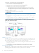
Figure 3 Journals Data path The physical transmission link between the local and remote systems is called the data path. Continuous Access Journal commands and data are transmitted through the fibre channel data path and switches. The data path is connected to the primary and secondary systems through two types of Fibre Channel ports, Initiator and RCU Target ports. One data path connection is required for Continuous Access Journal.
NOTE: • Administrator or Continuous Access Journal write access to the Remote Web Console Java applet program is required to perform these operations. Users without Administrator or Continuous Access Journal write access can only view Continuous Access Journal information. • If the RAID Manager computer is not installed, contact your HP account team for information on Continuous Access Journal configuration services.
NOTE: • If you manipulate volumes (not journals) to create or resynchronize two or more data volume pairs within the same journal, the base journal data for these pairs will be stored in the restore journal. Therefore, the operation for restoring the latter base journal will be delayed. • You can specify None as the copy mode for initial copy operations. If the None is specified, initial copy operations are not performed.
pair or journal returns to Paired status when the primary and secondary storage systems are re-synchronized. Read and Write I/O operations during remote copy operation The primary system reads from the P-VOL when it receives a read I/O. If the read fails, the redundancy provided by RAID-1 or RAID-5 technology recovers the failure. The primary system does not read the S-VOL for recovery.
The following provides a brief description of the pair statuses. For complete details, see “Pair status definitions” (page 67) . 16 • SMPL: A volume that is not assigned to a pair is in Simplex status, SMPL. • COPY: When copy processing is started, the primary system changes the status of the P-VOL and S-VOL to COPY. • PAIR: When the initial copy processing is complete, the primary system changes the status of both data volumes to PAIR.
2 Requirements and specifications This chapter provides system requirements for Continuous Access Journal. System requirements Continuous Access Journal operations are performed between the host(s) and the primary and secondary storage systems containing the P-VOLs and S-VOLs, using the data path. General requirements for the Continuous Access Journal components are listed below.
Table 1 General system requirements (continued) Item Requirement Volumes • P-VOL and S-VOL must be equal in size. • P-VOL and S-VOL must be of same emulation type. • The maximum volume size of P-VOL and S-VOL is 4,194,304.000MB (8,589,934,592Block). However, when XP12000 Disk Array or XP10000 Disk Array is used as the primary or secondary storage system, the maximum volume size is 2,949,120.00MB (6,039,797,760Block). • The minimum volume size of P-VOL and S-VOL is 48.000MB (96,000Block).
Table 1 General system requirements (continued) Item Requirement RAID Manager consistency groups • Up to four journals can be registered in one RAID Manager consistency group. when multiple primary and If there are four storage systems, you must create one journal for each storage secondary storage system system. • Up to 8,192 pairs, the total number of pairs registered in the journals in one RAID Manager consistency group can be registered.
3 Planning volumes and systems This chapter provides information and instructions for planning Continuous Access Journal volumes, P9500 systems, and other important requirements and restrictions. Plan and design workflow Planning the Continuous Access Journal system is tied to your organization’s business requirements and production system workload. This means defining business requirements for disaster downtime and measuring the amount of changed data your system produces over time.
To ensure that journals can hold the amount of data that could accumulate, they must be sized according to the following: • The maximum amount of time that journals could accumulate data. You develop this information by determining your operation’s recovery point objective (RPO). • The amount of changed data that your application generates. This is done by measuring write-workload.
To measure write-workload and IOPS 1. 2. Using your performance monitoring software, collect the following: • Disk-write bytes-per-second (MB/s) for every physical volume that will be replicated. • Data should be collected over a 3 or 4-week period to cover a normal, full business cycle. • Data should be collected at 5 minute intervals. If you use averages, shorter intervals provide more accuracy.
Calculating the journal size You calculate the size of journal volumes using write-workload and RPO. To calculate the journal size • Follow the instructions in (page 21). • Use your system's peak write-workload and your organization's RPO to calculate the journal size. For example: RPO = 2 hours Write-workload = 30 MB/sec Calculate write-workload for the RPO.
The ability of your Continuous Access Journal system to transfer data in a timely manner depends directly on the following two factors: • RAID group configuration • Fibre Channel port configuration Both of these elements must be planned to be able to handle the amount of data and number of transactions your system will move under extreme conditions.
Planning pair volumes The following information is provided to help you prepare volumes for configuration. Also, see system requirements and specifications in “Requirements and specifications” (page 17) for more information. • The emulation and capacity for the S-VOL must be the same as the P-VOL • When the S-VOL is connected to the same host as the P-VOL, the S-VOL must be defined to remain offline.
To determine the number of cylinders Use the following formula: The number of cylinders = (ceil ( (ceil (Max.
Table 3 Priority set for P-VOLs for which initial copy operation is performed P-VOL Value set for Priority LUN 00 2 LUN 01 3 LUN 02 1 LUN 03 4 The order of starting initial copy and the Priority which is set for the P-VOLs are shown in the following table.
Table 6 Order of starting initial copy being performed (continued) Order of starting initial copy P-VOL Value set for Priority Remark 5 LUN 11 1 Data volume pair for which initial copy is newly instructed to be performed 6 LUN 10 2 Data volume pair for which initial copy is newly instructed to be performed Priority is determined within the range of the number of initial copy operations performed at the same time.
◦ Data Retention ◦ Performance Monitor Planning for Continuous Access Journal with multiple P9500 systems A Continuous Access Journal system can be configured with up to four primary P9500 systems and four secondary P9500 system. Any combination of primary and secondary systems, from one to four, may be used. Figure 4 (page 29) shows an example configuration with multiple primary and secondary systems.
Figure 5 (page 30), Figure 6 (page 30), and Figure 7 (page 31) show varying configurations of storage systems in which multiple journals are registered in a single RAID Manager consistency group.
Figure 7 RAID Manager consistency group with multiple journals—3 Planning for previous models Continuous Access Journal can be used to perform remote copy operations between P9500 and XP24000/XP20000 Disk Array. Data can be copied from P9500 to XP24000/XP20000 Disk Array, or vice versa. To execute remote copy from P9500 to XP24000/XP20000 Disk Array or vice versa, set up the following: • Configure a logical path between LDKC00 of the P9500 system and the XP24000/XP20000 Disk Array.
• P9500 and XP24000/XP20000 Disk Array can be set up in 3-data center (3DC) cascading or multitarget configurations. These configurations are used when combining Continuous Access Synchronous and Continuous Access Journal systems. See “Continuous Access Journal configurations with Continuous Access Synchronous” (page 130) to review these configurations. There are no restrictions for the combining primary ad secondary sites between P9500 and XP24000/XP20000 Disk Array .
System option modes HP provides system option modes to tailor customer requirements on the P9500 system.
Table 7 System option modes (continued) Mode Description Mode 760 OFF: Normal operations are performed. System option modes can only be changed by an HP representative.
4 Planning the data path A data path must be designed to manage your organization’s throughput to the remote site. Appropriate bandwidth, required number of ports, and the Fiber Channel data path configuration you use help insure that your update data arrives at the remote site in a time consistent with your organization’s RPO. This chapter provides instructions for calculating bandwidth and designing the data path network.
• If you cannot determine a “typical” workload, sizing should be to the average or mean workload, plus a small compensation for network overhead. In this scenario, excess data in the journals will be completely emptied to the S-VOL only occasionally. If bandwidth is sized below average write-workload, the journals never fully drain and eventually overflow resulting in the pairs suspending.
workload to abnormally high levels. It is sometimes worthwhile to review the processes that are running. After careful analysis, it may be possible to lower or even eliminate some spikes by optimizing or streamlining high-workload processes. Also, changing the timing of a process may lower workload. 3. With a base bandwidth value established, make adjustments for growth and a safety factor. • Projected growth rate accounts for the increase expected in write-workload over a 1, 2, or 3 year period.
For another perspective, you can graph the data, as shown in Figure 11 (page 38). Figure 11 60-minute rolling averages graphed over raw data 2. 3. From the spreadsheet or graph, locate the largest or highest rolling average value. This is the peak rolling average, which indicates the base amount of data that your bandwidth must be able to handle. With a base bandwidth value established, make adjustments for growth and a safety factor.
Planning ports for data transfer Updated data is transferred along the data path from the initiator and RCU target ports on the primary and secondary systems. • Initiator ports control the specific data link they are part of. • RCU target ports respond to commands from Initiator ports. • The amount of data a port can transmit is limited. Continuous Access Journal transfers data from the primary to the secondary storage system when the secondary storage subsystem requests data.
number of ports for a Continuous Access Journal Z system is two. To determine the required number of initiator and RCU target ports. 1. Measure IOPS for your production system. When you measure write-workload, IOPS is also provided. (See “Measuring write-workload” (page 21)). 2. Using peak IOPS and the maximum IOPS for a VSP Fibre Channel port (70,000), calculate the number of ports your Continuous Access Journal Z system requires. Peak IOPS / 70,000.
This information is illustrated in Figure 12 (page 41). Figure 12 Data path types, switches, and distances Supported data path configurations The remote data path can be configured in one of the following connection types. But for switch connection, the port should be set to Fabric on, Point-to-Point (F-port). • Direct connection, as shown in Figure 13 (page 41). Direct connection (loop only) is a direct link between the local and remote arrays.
Figure 14 Switch connection configuration Figure 15 Extender connection configuration NOTE: 42 • When an MCU and RCU are connected using switches with channel extenders, and multiple data paths are assembled, the capacity of data to be transmitted may concentrate on particular switches, depending on the configuration and the settings of switch routing. • Make sure that your channel extenders are capable of supporting remote I/O. For further details, contact your HP account team.
5 Configuration operations This chapter provides the configuration tasks that will make your primary and secondary systems ready for Continuous Access Journal pair operations. Configuration workflow You will set up primary and secondary systems for Continuous Access Journal operations as follows. Check the prerequisites for each procedure. Some tasks need to be performed from both local and remote storage systems and other tasks need to be performed from the local or remote storage system. 1.
• • Before a fiber channel initiator port can be changed to target or RCU target, the following must be performed: ◦ All affected data volume pairs must be released. ◦ All logical paths must be deleted from the initiator port to the remote storage system. ◦ After logical paths are deleted, cables connecting the local system to the remote system must be removed. The number of hosts connected to a target port must be limited to 128 or fewer to avoid illegal disconnection.
Configure storage systems for Continuous Access Journal, define logical paths Prerequisite Information • This procedure must be performed on both primary and secondary systems. • The primary and secondary systems must already be configured for Continuous Access Journal operations. See “System requirements” (page 17) for more information. • The data path must be set up. See “Planning the data path” (page 35) for more information.
5. 6. In the S/N box, enter the remote system’s 5-digit serial number. In the LDKC box, select the remote system’s LDKC number. Enter 00 when the remote system is P9500, XP24000/XP20000 Disk Array, or XP12000 Disk Array/XP10000 Disk Array. 7. 8. 9. In the Controller ID box, select the remote system’s controller ID. The controller ID for a P9500 storage system is 6. The controller ID for a XP24000/XP20000 Disk Array storage system is 5.
11. The Minimum Paths box is intended for a future release. Continue to the next step. 12. RIO MIH means “Remote I/O Missing Interrupt Handler”. In the RIO MIH Time box, enter the amount of time from 10 seconds to 100 seconds (15 seconds is the default). 13. Click Set. 14. See the Preview list to check the settings that you have made. • If you want to modify a setting, select and right click the item in the Preview list and then select Modify.
6. In the M-R Path box, define the Fibre Channel port used by logical path between local and remote systems: 1. In the Port, select a local system initiator port. 2. In the Pair-Port, select the remote system RCU target port. You may enter port numbers using the keyboard. You may abbreviate the number into two characters. For example, “1A” may be entered instead of “CL1-A”. Letters may be uppercase or lowercase. 7. 8. 9. Click Set and close the Add Path dialog box.
To specify number of volumes to copy concurrently 1. In Remote Web Console, select Actions > Remote Copy > Continuous Access Journal > Optional Operation. 2. 3. Click to change the mode from View to Modify. Right-click the value that displays under Activities in the right-side pane, then select Change System Option from the menu. The System Option dialog box displays. 4.
Register journal volumes in a journal You set up journal volumes by registering them in a journal. The procedure is provided below. Prerequisite information • The emulation type of the volume that can be registered in the journal is only OPEN-V. For details, see (page 17). • Journal volumes must be registered in a journal before the initial pair-copy operation is performed. • Journal volumes must be registered on both local and remote systems. • A journal can contain up to 64 journal volumes.
2. 3. Click to change the mode from View to Modify. To register journal volumes in an existing journal, select the journal from the Registered tree. To register journal volumes in a new journal, select the journal from the Free tree. The selected journal displays in the upper-right list of the window. The journal volume cannot be registered when there are mirrors other than the following statuses in the journal of the Registered: Status: Initial, Active, Stopped, Hold, Holding, or Hold(Failure). 4.
7. 8. 9. Click Set to close the Edit Journal Volumes dialog box. See the Preview list in the Journal Operation window to check the journal volumes that you have added. • If you want to add a another volume, select the journal to add a volume in the Preview list and right click and then select Modify. If the window opens, add a volume. • If you want to cancel a setting, select the volume in the Preview list and right click and then select Cancel. Click Apply to register journal volumes.
6 Pair operations This chapter provides procedures and prerequisite information for performing Continuous Access Journal copy operations. Pair operations workflow Basic Continuous Access Journal operations consists of the following. • Always check pair status. Each Continuous Access Journal operation requires the pair to be in a specific status. • Create the pair, in which the S-VOL becomes a duplicate of the P-VOL.
• If you are creating a Continuous Access Journal pair for delta resync, make sure all requirements are met. See “Creating a delta resync pair ” (page 137). • If this program product is running on a primary storage system or secondary storage system, stop Performance Monitor before performing the initial copy to avoid overloading with TCP/IP traffic. For details about Performance Monitor, see HP P9000 Performance for Open and Mainframe Systems User Guide. To create an initial copy or copies 54 1.
5. • Data for the selected volume displays in the P-VOL box. The numbers indicate the port, GID, LUN, and volume. • One P-VOL displays at a time, even if you selected multiple volumes for pairing. The volume with the lowest number displays first. Specify an S-VOL as follows: 1. Select the port, GID, and LUN from the three S-VOL , left to right. If you selected multiple volumes as P-VOLs, the S-VOL you specify by the list is paired with the P-VOL displayed in P-VOL.
2. If multiple pairs are created at one time, use the Select Other S-VOL(s) list to specify S-VOLs. If you selected multiple volumes as P-VOLs, you can instruct the system to automatically assign S-VOLs for the remainder of P-VOLs. Do this from the Select Other S-VOL(s) list, as follows: - Select Increment to cause Continuous Access Journal to add the secondary system LUN incrementally. Your S-VOL LUN numbers must be numbered incrementally.
by the CU configuration or a remote copy path error. Review the error, release the pair with the error, and then retry the Paircreate operation. 10. In the Error Level list, select one of the following options to take place in the event a failure occurs during this operation: • Mirror, to cause all pairs in the failed pair’s mirror to be split. Mirror is the default. • LU, to cause only the pair that failed to be split. 11. Click Set to close the Paircreate dialog box. 12.
To split one or more pairs 1. In Remote Web Console, select Actions > Remote Copy > Continuous Access Journal > Pair Operation. 2. 3. Click to change the mode from View to Modify. In the tree, select the port or host group. Paired volumes are displayed in the upper-right-side list area. Select the pair that you want to split, right-click, and select Pairsplit-r from the menu. The dialog box displays. 4. 5. 6.
9. See the Preview list to check the settings that you have made. • If you want to modify a setting, select and right click the item in the Preview list and then select Modify. • If you want to delete a item, select and right click the item in the Preview list and then select Delete. 10. Click Apply to apply the settings. If an error occurs during creating pairs, right click the item in the Preview list and select Error Detail. You can verify the PSUS status when the operation is completed.
Restore a pair If the pair is restored, the suspended data copy from the primary data volumes to the secondary data volumes is resumed. If the delta resync pair is restored, the delta resync processing is performed. This section describes the pair resync operation. Also, the instructions are used when performing the delta resync operation. Prerequisite information • The pair resynchronizing operation is performed from the primary storage system only. • Pairs in PSUS or PSUE status is resynchronized.
• If you used the Continuous Access Journal pair for delta resync operation as the master journal after a power supply error occurred at the primary storage system, resynchronize the pair, and then execute I/O operation from the host. • The Continuous Access Journal delta resync S-VOL cannot be used with Business Copy or Thin Provisioning. • After the delta resync operation (when pair status has changed to PAIR), the delta resync P-VOL must be updated from the host for longer than five minutes.
- The Range column shows Mirror for at least one of the above pairs. To be able to continue processing, do either of the following: - Ensure that the Range column shows LU for all pairs in the same mirror. - In the Preview list, select one pair in one mirror, and then other pairs in the mirror is excluded. 6. 7. 8. 9. From the Priority list, specify the scheduling order for resynchronizing selected pairs. If Range is Mirror, the Priority list is disabled.
consists of multiple primary and secondary storage systems (see Figure 4 (page 29)). Because the Remote Web Console does not support the system that consists of multiple primary and secondary storage systems, an error occurs if you try to restore a mirror by using the Remote Web Console in this system configuration. • Best practice is to resynchronize when I/O load is low. This reduces impact on performance.
• In a delta resync configuration, if you release the Continuous Access Synchronous pair, the Continuous Access Journal delta resync pair will be released as well. If you release the Continuous Access Journal pair, the Continuous Access Journal delta resync S-VOL is released.
6. From the Delete Mode list, select one of the following: • Normal, to delete the pair or pairs only if the primary system is able to change the pair status of both P-VOL and S-VOL to SMPL. • Force, to forcibly delete the pair or pairs, even when the primary system is unable to communicate with the secondary system. This option could be used, for example, when the primary system is unable to communicate with the secondary system. Specifying Force would thus allow host operations to continue.
6. See the Preview list in the Journal Operation window to check the settings that you have made. If you want to cancel a setting, select and right click the setting and then select Delete. 7. 66 Click Apply to apply the settings. If an error occurs, the error code appears in the rightmost column of the Preview list. To view detailed information about the error, right click the error code and select Error Detail.
7 Monitoring the system Monitoring pairs, journals, and data paths should be checked frequently to ensure that Continuous Access Journal pairs are operating correctly. Pair status should be checked before performing a Continuous Access Journal operation. Each operation requires specific pair status. Monitor pair activity and status Monitoring the Continuous Access Journal system is an ongoing operation that should be performed frequently to maintain your pairs.
Pair status Description P-VOL access S-VOL access • When the operation is performed at the secondary system, the status of the S-VOL changes to PSUS; the primary system detects this (if path status is normal) and changes P-VOL status to PSUS. • When a pair is released from the secondary system, the secondary system changes the status of the S-VOL to SMPL. The primary system detects this (if path status is normal and changes P-VOL status to PSUS.
Pair status Description P-VOL access S-VOL access HOLD • The pair or command devices are ready for the delta resync operation. When the status of the Cnt Ac-J P-VOL is HOLD, incoming write data for the Cnt Ac-S S-VOL is stored in the master journal volume. Read/Write*1 Read/Write*2 • Operations allowed on the pairs in HOLD status: - Delta resync - Pair-delete - Changing pair options HOLDING *4 The pair status is changing to Hold so that the delta resync pair Read/Write*1 can be created.
Pair status Description P-VOL access S-VOL access *2: The Cnt Ac-J S-VOL in HOLD status uses two mirrors. Accessing the S-VOL depends on the status of the mirror whose status is not HOLD. *3: A host cannot write data to the Cnt Ac-J P-VOL when it belongs to a journal that was registered when 2DC Cascade is set to Enable in the Edit Journal Volume dialog box.
See “Usage Monitor window ” (page 177) for instructions on viewing the usage rate of a journal volume. • When the pair status is COPY, you cannot add cache or shared memory to or remove it from the storage system. Before performing either of these tasks, split any pairs with COPY status, and then resynchronize the pairs when the cache or shared memory operation is complete. PSUS types and behaviors The PSUS status can be initiated by the user or the system, from the primary or secondary systems.
Table 8 S-VOL consistency statuses Consistency status Description Volume • Only the current pair was split or suspended. • Update sequence consistency between this S-VOL and other S-VOLs in the associated journal is not insured. • This S-VOL cannot be used for disaster recovery at the secondary site. • This status is indicated when: - The pair is split by the user using the Suspend Range-Volume (LU) pairsplit option. - The pair is suspended due to a failure that did not affect the entire journal.
When a pair is suspended, the primary system stops performing journal-obtain operations for the pair. However, the primary system continues the following operations: • Continues accepting write I/Os for the suspended P-VOL • Keeps track of the P-VOL cylinders/tracks that are updated • Keeps track of journal data discarded during the pair suspension. (Both primary and secondary systems do this.
• Set: Applies the settings in the Display Filter dialog box to the list. • Cancel: Discards the settings and closes the dialog box. Saving pair status information into a text file You can use the export function only while the client file access is enabled. When the client file access is not enabled, the Export is not available on the Pair Operation window. For the further information of the client file access settings, see HP P9000 Remote Web Console User Guide.
2. 3. In the Pair Operation window, click Export. A message appears and asks whether to save volume pair information in a file. Click OK to close the message. A dialog box appears and prompts you to save a file. 4. Enter the name of the file and then click Save. A message appears. 5. Click OK to close the message. If Subsystem or an LDKC is selected in the tree, you can abort the exporting by clicking Cancel in the dialog box that is open during the export processing.
Table 9 Fields on the Usage Monitor window (continued) Field Description Update The most recent data sample time of data on the graph. Usage Monitor Graph Remote I/O statistics and status of remote copy monitor. Select data to be graphed The usage monitor graph plots the I/O data that you specify. On the graph: • The x-axis indicates time. • The y-axis indicates the number of I/Os during the sampling period. • The legend on the right side shows the data being displayed.
5. Click Set to close the Display Item dialog box. The Usage Monitor window now shows a graph of the selected I/O statistics data for the selected LU(s). Table 10 Remote copy I/O statistics data Data type Description Host I/O Write Record Count The number of write I/Os per second. Write Transfer Rate The amount of data that are written per second. The unit is kilobytes per second. Initial Copy Initial Copy Hit Rate The initial copy hit rate. The unit is percent.
Table 10 Remote copy I/O statistics data (continued) Data type Description R-JNL Average Transfer Rate The average transfer rate for journals in the secondary storage system. The unit is kilobytes per second. R-JNL Average RIO Response The remote I/O process time on the secondary storage system. The unit is milliseconds. M-JNL Data Used Rate Data usage rate for master journals. The unit is percent. Meta Data Used Rate Metadata usage rate for master journals. The unit is percent.
Status Halting Description An operation for splitting or deleting the mirror is in progress. • Splitting a mirror changes the status in the following order: Halting, Halt, Stopping, and finally Stopped. • Deleting a mirror changes the status in the following order: Halting, Halt, Stopping, Stopped, and finally Initial. Halt Stopping Stopped Hold Holding Hold(Failure) Blank An operation for splitting or deleting the mirror is in progress. An operation for splitting or deleting the mirror is in progress.
Item Description - The port in the remote system is physically disconnected from the local system. • Pair-Port Type Mismatch. The port on the remote system is not an RCU target port. • Communication Failed. A communication timeout error has occurred on the path between the local and remote systems. Port Port on the local system. Pair-Port Port on the remote system. S/N Serial number and LDKC number of the remote system.
8 Maintaining the system Some maintenance tasks are a response to behavior discovered during system monitoring. However, you can also change certain settings to keep the system in tune with your changing requirements. Pair maintenance—change the pair-split option You can change the option that specifies whether a pair-split operation that is triggered by pair failure is applied to all the pairs in the mirror, or only to the affected pair. This option was first set during the pair create operation.
Change Continuous Access Journal options used by journals Most Continuous Access Journal pair operations are performed on multiple pairs. This is done using journals.
4. For Inflow Control, specify whether to restrict inflow of update I/Os to the journal volume (slows delay response to hosts). For example, you could have a 100 GB-bandwidth data path with three journals using it. If an important database is saved to a primary volume in one of the journals, with data of lesser importance in the other journals, you may decide to restrict the Inflow Control for the less important journals while not restricting control to the important journal.
Change Continuous Access Journal options used by mirrors Most Continuous Access Journal pair operations are performed on multiple pairs. This is done using a journal or mirrors. You can change the following options that affect the pairs in a mirror: • Unit of Path Watch Time—establishes the unit of path watch time. • Path Watch Time—establishes the amount of time before a blocked path results in the mirror being split.
4. 5. 6. For Copy Pace, specify the pace for initial copy activity per volume. This field cannot be specified on the remote system. Low is the default. When specifying Medium, insure that write I/O is 10 MB/s or less per parity group. If it exceeds 10 MB/s, pairs may be suspended. When specifying High, insure that I/O will not occur. If update I/O occurs, pairs may be suspended. For Unit of Path Watch Time, specify the unit of time for Path Watch Time, minute, hour, or day.
9. For Delta resync Failure, specify the processing that takes place when the delta resync operation cannot be performed. (This option specified on the primary storage system only.) - Entire, the default. The entire P-VOL is copied to the S-VOL. - None: No processing and the S-VOL is not updated. 10. Click Set when finished. 11. See the Preview list to check the settings that you have made. • If you want to modify a item, select and right click the setting in the Preview list and then select Modify.
8. 9. See the Preview list to check the settings that you have made. • If you want to modify a setting, select and right click the item in the Preview list and then select Modify. • If you want to delete a item, select and right click the item in the Preview list and then select Delete. • If necessary, repeat steps from 2 to 6 to specify volumes that should be deleted from other journals. Click Apply to apply the settings and create pairs.
Prerequisite information • Modifying the data-transfer threshold can be performed from the primary storage system or secondary storage system. • The setting is made in the RIO MIH field on the DKC Options dialog box (RIO MIH--remote I/O missing interrupt handler). To change the data-transfer threshold time 1. In Remote Web Console, select Actions > Remote Copy > Continuous Access Journal > DKC Operation. The DKC Operation window displays. 2. 3. Click to change the mode from View to Modify.
6. See the Preview list to check the settings that you have made. If you want to delete a item, select and right click the item in the Preview list and then select Delete. 7. Click Apply to apply the settings. If an error occurs, select and right click the item in the Preview list and select Error Detail.
When power is removed from primary or secondary system • If power is removed from the primary system during remote copy operations, the primary system assumes that a failure has occurred and splits all pairs. When the primary system splits pairs, the secondary system also assumes that a failure occurs and splits all pairs. • If power is removed from the secondary system during remote copy operations, the secondary system assumes that a failure has occurred and splits all pairs.
2. 3. 4. 5. 6. After the pairs are split, confirm that their status is PSUS at the primary system. Power off the primary system. Power off the secondary system. Power on the secondary system. When the secondary system is ready to resume copy operations, power on the primary system. CAUTION: Wait five (5) minutes after powering on a system before performing Continuous Access Journal operations; otherwise the pairs could be suspended with a failure. 7.
9 Disaster recovery operations This chapter provides guidelines for performing disaster recovery operations. Also included are disaster recovery procedures when Continuous Access Journal is configured with Continuous Access Synchronous and Business Copy. Preparing for disaster recovery The major steps for preparing for disaster recovery are: • Identify the data volumes that you wand to back up for disaster recovery. • Pair the important volumes using Continuous Access Journal.
The following procedure explains how to re-establish control of the Continuous Access Journal pairs and copy data from the secondary site to the primary site: Procedure 1 1. 2. 3. 4. Restore the primary system and remote copy connections. Bring up the host server(s) at the primary site. Make sure that all Continuous Access Journal components are operational. Do all of the following, as applicable: 1. At the primary site, locate P-VOLs whose status is COPY or PAIR.
7. Execute the pairresync -swaps command, which reverses P-VOLs and S-VOLs and resynchronizes the pairs. Copy flow is from the primary site to the secondary site (was disaster recovery site). NOTE: When you execute the pairresync -swaps command, you can use the -d option to specify a data volume. However, the command is rejected if the restore journal where the data volume belongs is in Active, Halting or Stopping status.
Figure 17 Flow of the case of transferring the business tasks from the remote to primary site Recovery procedures with shared volumes Restoring operations with shared Continuous Access Journal and Continuous Access Synchronous or Business Copy volumes is a bit more complicated than with a straight Continuous Access Journal pair. The following sections provide various procedural guidelines.
Recovery in a 3DC cascade configuration If a disaster or failure occurs in the primary site of a 3DC cascade configuration, you transfer business operations to the intermediate Continuous Access Synchronous secondary volume (S-VOL) site. After this is done, the primary site should be corrected and brought back online. Then, you have choices for proceeding: re-create the cascading configuration, or change the Continuous Access Journal/Continuous Access Synchronous configuration to multitarget.
4. Check the execution result of the horctakeover command, and then do either of the following: Procedure 2 1. 2. If the primary/secondary relationship of the Continuous Access Synchronous pair is not reversed (that is, the copy direction is not reversed), use RAID Manager to create a Continuous Access Journal pair. P-VOL of the Continuous Access Journal pair must be the Continuous Access Synchronous secondary volume.
Transferring business tasks from Continuous Access Synchronous secondary to primary site (in 3DC multitarget configuration) If you remove failures from the primary site and other locations and then the system is changed to 3DC multitarget configuration, you can transfer your business tasks back to the primary site. To transfer your business tasks back to the primary site, follow the procedure below. RAID Manager (RAID Manager) is used in this procedure: 1.
Table 12 Changes of Continuous Access Journal pair status by delta resync operation (when recovering from failures in the primary site) Cnt Ac-J pair Pair status before delta resync operation Pair status after delta resync operation P-VOL S-VOL P-VOL S-VOL Cnt Ac-J pair between Continuous Access Synchronous primary site and Cnt Ac-J secondary site PAIR, PSUS, or PSUE PAIR, PSUS, or PSUE HOLD HOLD Cnt Ac-J pair between Continuous Access Synchronous secondary site and Cnt Ac-J secondary site HOLD
CAUTION: When transferring business tasks back to the primary site when using delta resync: After you remove failures from the primary site and other locations and then the system is changed to 3DC multitarget configuration (see “Recovering from primary site failures (when delta resync operation is performed)” (page 98)), the status of a pair between the primary site and the Continuous Access Journal secondary site may be abnormal.
Transferring business tasks from the Continuous Access Journal secondary to the primary Site If you follow the instructions in the previous section and then remove failures from the primary site and the Continuous Access Synchronous secondary site, you can transfer your business tasks back to the primary site. To transfer your business tasks back to the primary site, follow the procedure below. RAID Manager (RAID Manager) is used in this procedure: 1.
3. 4. 5. After the new Continuous Access Synchronous pair is in PAIR status, stop host operations at the remote site, then release the Continuous Access Synchronous pair. On the intermediate site, create a Continuous Access Journal pair to the Continuous Access Journal remote site, with no data copying (specify None on the Copy Mode option). Specify the intermediate site volume as the Continuous Access Journal P-VOL and the remote volume as the Continuous Access Journal S-VOL.
10 Troubleshooting This chapter provides troubleshooting information. General troubleshooting General troubleshooting information for Continuous Access Journal follows. Table 15 General troubleshooting Error Corrective action Remote Web Console hangs, or Cnt Ac-J operations do not function properly. Make sure that the problem is not being caused by the computer or Ethernet hardware or software, and restart the computer.
Table 15 General troubleshooting (continued) Error Corrective action Monitoring Switch, see HP P9000 Performance for Open and Mainframe Systems User Guide. Troubleshooting logical paths Troubleshooting information for logical paths between storage systems is shown below. Table 16 Logical path troubleshooting Path status Description Initialization Failed The link initialization procedure for the secondary system failed.
Table 16 Logical path troubleshooting (continued) Path status Description Corrective action Port number invalid The specified port number is invalid. The cable is not connected to the specified port. Delete the failed path. Check the specified port number or the cable connection and then retry. Communication error A timeout error has occurred in the path between the primary and secondary systems. Delete the failed path and retry.
Troubleshooting suspended pairs Troubleshooting information for user-suspended and system-suspended pairs is provided in the following two tables. Hardware failures affecting the cache memory and the shared memory of the primary or secondary system may also cause the pairs to be suspended.
Table 18 Resolving pair suspension (continued) Classification Causes of suspension SIM Journals cannot be retained because some portion of the cache memory or the shared memory has been blocked due to hardware failure. Recovery procedure remain, execute the pairresync -swaps command on the secondary volumes whose pair status is SSWS (pairresync is the RAID Manager command for resynchronizing pair and -swaps is a swap option. This operation changes all volumes in the master journal to primary volumes.
(see HP P9000 Remote Web Console User Guide). If you are unable to resolve an error condition, contact the HP Technical Support. Error codes When an error occurs in a Continuous Access Journal pair operation when using Remote Web Console, an error message displays with a four-digit error code and description. An SVP error code may also be included. See HP P9000 Remote Web Console Messages for details on error codes. If you need to call HP Technical Support for assistance, report the error code(s).
Table 19 RAID Manager error codes for Continuous Access Journal (continued) Error code (SSB1) Error code (SSB2) Error content HOLDTRNS status. Or, the Cnt Ac-J pair cannot be resynchronized (ALLJNL parameter specifying), because the specified P-VOL is not in the either of HOLD, HOLDTRANS, or NODELTA status.
Table 19 RAID Manager error codes for Continuous Access Journal (continued) Error code (SSB1) Error code (SSB2) Error content 8F00 A request of Cnt Ac-J Paircreate was rejected because the specified volume was the external volume. 8F10 The Cnt Ac-J pair cannot be created because the specified volume is part of a Business Copy or Flash Copy pair. 8F11 The Cnt Ac-J pair cannot be created. The processing of volume migration could not be stopped because the P-VOL was being migrated by Auto LUN.
Table 19 RAID Manager error codes for Continuous Access Journal (continued) Error code (SSB1) Error code (SSB2) Error content 8F39 A request of Cnt Ac-J pair create was rejected because the program product of Cnt Ac-J was not installed. 8F46 The Cnt Ac-J pair cannot be created because cache CL2 is in abnormal status. 8F47 The Cnt Ac-J pair cannot be created because cache CL1 is in abnormal status.
Table 19 RAID Manager error codes for Continuous Access Journal (continued) Error code (SSB1) 112 Troubleshooting Error code (SSB2) Error content B90B A request of Cnt Ac-J Paircreate was rejected because the consistency group number is wrong. B90E A request of Cnt Ac-J Paircreate was rejected because the path is not set between the systems. B90F A request of Cnt Ac-J Paircreate on the Cnt Ac-J intermediate volume was rejected because either Cnt Ac-J Z or Cnt Ac-S Z was not installed.
Table 19 RAID Manager error codes for Continuous Access Journal (continued) Error code (SSB1) Error code (SSB2) Error content E87D A request of Cnt Ac-J Pairresync was rejected because the specified volume was not for the Cnt Ac-J pair. E87E A request of Cnt Ac-J Paircreate was rejected because the specified P-VOL or S-VOL was a journal volume. E880 A request of Cnt Ac-J Paircreate was rejected because the emulation type was different between the specified P-VOL or S-VOL and the journal volume.
Table 19 RAID Manager error codes for Continuous Access Journal (continued) Error code (SSB1) 114 Troubleshooting Error code (SSB2) Error content EA07 A request of Cnt Ac-J Paircreate was received. However, the Cnt Ac-J pair cannot be created because the number of the Cnt Ac-J pair registrations in the primary journal exceeds the upper limit. EA08 A request of Cnt Ac-J Paircreate was received.
Table 19 RAID Manager error codes for Continuous Access Journal (continued) Error code (SSB1) Error code (SSB2) Error content EA41 A request of Cnt Ac-J Paircreate was rejected because the desired capacity exceeded the charging capacity of the secondary system’s program product. EA8B A request to delete or suspend a Cnt Ac-J pair was rejected because the specified volume is used in the system that consists of multiple primary and secondary systems.
Table 19 RAID Manager error codes for Continuous Access Journal (continued) Error code (SSB1) Error code (SSB2) Error content EB28 A request to create or resynchronize a pair in the system that consists of multiple primary and secondary systems was rejected because the Cont Access Journal 3DC & 4x4 Open MF program product was not installed in the secondary system.
Table 19 RAID Manager error codes for Continuous Access Journal (continued) Error code (SSB1) Error code (SSB2) Error content EB60 A request was rejected by either of the following reasons: • The volume capacity of P-VOL was does not conform with the volume capacity of S-VOL. • Capacities of each volumes that are concatenated in LUSE on the primary site does not conform with capacities of each volumes that are concatenated in LUSE on the secondary site.
Table 19 RAID Manager error codes for Continuous Access Journal (continued) Error code (SSB1) Error code (SSB2) Error content EB88 The Cnt Ac-J pair was not created because of one of the following: • The specified S-VOL was being used as a Business Copy S-VOL. • The specified S-VOL was Not Ready, which means that the hard disk drive cannot be used. EB89 A request of Cnt Ac-J Paircreate was rejected because the emulation types of the specified P-VOL and S-VOL were not the same.
Table 19 RAID Manager error codes for Continuous Access Journal (continued) Error code (SSB1) Error code (SSB2) Error content EBDC A request for a Cnt Ac-J pair operation was received but cannot be executed because the processing load of the storage system is heavy. Please execute the command again after a while. EBE0 A request of Cnt Ac-J Paircreate was rejected because the specified S-VOL was already used in the Cnt Ac-J pair for delta resync.
Figure 18 Typical SIM with reference code and SIM type NOTE: The SIMs shown below are reported to the host, except 21 81. The following table shows SIMs reference codes, and provides useful information for identifying issues and determining the system experiencing the problem. All SIMs are reported to the host, except 21 80.
Table 20 SIM reference codes, types, and descriptions (continued) Reference code Byte 22 Severity Description System generating the SVP log SIM file Byte 23 A failure has been detected in the secondary system. DC 9X Serious A volume being used by P-VOL of the Cnt Yes, repeatedly. Ac-J Z pair for delta resync operation has been suspended. Primary storage system A failure has been detected in the primary storage system.
11 Support and other resources Contacting HP For worldwide technical support information, see the HP support website: http://www.hp.
HP websites For additional information, see the following HP websites: • http://www.hp.com • http://www.hp.com/go/storage • http://www.hp.com/service_locator • http://www.hp.com/support/manuals • http://www.hp.com/support/downloads • http://www.hp.
Table 21 Document conventions (continued) Convention Element Monospace text • File and directory names • System output • Code • Commands, their arguments, and argument values Monospace, italic text • Code variables • Command variables Monospace, bold text WARNING! CAUTION: IMPORTANT: NOTE: TIP: 124 Emphasized monospace text Indicates that failure to follow directions could result in bodily harm or death. Indicates that failure to follow directions could result in damage to equipment or data.
A Sharing Continuous Access Journal volumes This appendix discusses non-Continuous Access Journal volumes that can be shared as Continuous Access Journal volumes. It discusses the volumes of several features that can be used in full or limited ways with Continuous Access Journal. Continuous Access Synchronous, Business Copy, and External Storage Access Manager volumes can be used extensively with Continuous Access Journal.
Table 22 Volume types that can be shared with Continuous Access Journal (continued) Volumes types Can the volumes be used as P-VOLs? Can the volumes be used as S-VOLs? Can the volumes be used as journal volumes? Source volume.
Table 22 Volume types that can be shared with Continuous Access Journal (continued) Volumes types Can the volumes be used as P-VOLs? Can the volumes be used as S-VOLs? Can the volumes be used as journal volumes? S-VOL in COPY status No No No S-VOL in PAIR status Yes No No S-VOL in PSUS status Yes No No S-VOL in SSWS status Yes No No S-VOL in PSUE status Yes No No Quorum disk No No No 1. 2. 3. 4. The volume cannot be used as a Cnt Ac-J data volume for delta resync.
LUN Manager • LUN Manager operations do not affect Continuous Access Journal operations. Volumes that are under secure ports and/or are assigned to host groups can also be assigned to Continuous Access Journal pairs. Volumes that are assigned to Continuous Access Journal pairs can be protected by LUN Manager. • Continuous Access Journal S-VOLs cannot be accessed by any UNIX or PC server host except when the pair is split.
Table 23 Status, availability of Data Retention operation (continued) Cnt Ac-J volume S-VOL Pair status Changing access attribute Referencing access attribute PSUE Yes Yes SMPL Yes Yes COPY No Yes PAIR No Yes PSUS No* Yes PSUE No Yes *Note: If the Write option is set to the S-VOL, the access attribute can be changed.
B Continuous Access Journal configurations with Continuous Access Synchronous Continuous Access Journal and Continuous Access Synchronous can share the same data volumes. Using Continuous Access Journal and Continuous Access Synchronous can extend disaster recovery options to a third data center. This chapter provides planning formation for sharing Continuous Access Journal volumes with Continuous Access Synchronous. It describes four Continuous Access Journal/Continuous Access Synchronous configurations.
3DC cascade configuration As illustrated below, the Continuous Access Synchronous P-VOL is the primary production volume in a 3DC cascade configuration. The Continuous Access Synchronous S-VOL is located at an intermediate site that is near the primary site. The host issues an update to the Continuous Access Synchronous primary volume (P-VOL), which is copied synchronously to the S-VOL. The Continuous Access Journal system copies the synchronous S-VOL data to the Continuous Access Journal remote site.
• Differential data is used to resynchronize a suspended Continuous Access Synchronous or Continuous Access Journal pair. • When the Continuous Access Synchronous pair is recovered, the Continuous Access Journal pair in PAIR or COPY status is automatically split by the system. • The fence level of the Continuous Access Synchronous P-VOL must be Data. • 3DC Cascade is not supported for multiple primary and secondary systems.
Failure recovery occurs as follows: • If a failure occurs in the P-VOL, business is resumed using the Continuous Access Synchronous S-VOL. When the failure is corrected at the primary site, business tasks are transferred back to the primary site. In addition, a quick disaster recovery solution can be put in place while the primary site is being restored, using a Continuous Access Journal pair for delta resync.
Delta resync configuration In a Continuous Access Journal delta resync configuration, you create a second Continuous Access Journal pair in a 3DC multitarget. The pair is created using the Continuous Access Synchronous secondary volume (S-VOL) and the Continuous Access Journal S-VOL, as illustrated in the following. The delta resync operation requires less time to bring the S-VOL to a consistent state after a failure occurs because only missing differential data needs to be copied.
Prerequisite information for creating the delta resync pair • A Continuous Access Journal delta resync pair is created in a 3DC multitarget configuration only. • Do not include the 3DC multitarget configuration in a system that consists of multiple primary and secondary storage systems. • Use Continuous Access Synchronous S-VOL in PAIR status as the primary data volume. • Use Continuous Access Journal data volume in PAIR status as the secondary data volume.
The following are also regarded as the case of creating the Continuous Access Journal pair for delta resync operation: ◦ When the Continuous Access Journal pair status changes to HOLD after the delta resync operation When you re-create the Continuous Access Journal pair for delta resync operation when recovering the primary site When the pair recovery operation is performed on the suspended Continuous Access Synchronous pair or Continuous Access Journal pair, allow the 3DC configuration to remain status f
If you specify the option of the delta resync operation, and the following conditions exist, errors occur and the delta resync operation fails: • The secondary volume of the Continuous Access Journal pair for delta resync operation is V-VOL. • The secondary volume of the Continuous Access Journal pair for delta resync operation is assigned to the primary volume of Business Copy or the primary volume of Snapshot.
3. On each site, map a command device via a target port to a device on one of the other sites. The device on the other site should be mapped to as a remote command device, using an external port on that system. 4. Repeat the previous step so that two command devices on each site are mapped to a remote command device on each of the other two sites. Thus: • Each site should have two command devices mapped via two target ports to the other two sites.
4. In the mirror list, right-click the mirror(s) that you want to assign to the remote command device and click Mirror > Assign R-Cmd. Dev from the menu that displays. The Assign Remote Command Device dialog box displays, as shown below. 5. Assign mirror IDs to remote command devices as follows. • On primary site: - Assign mirror ID 00 to the remote command device that is mapped to on the intermediate site.
Release a remote command device which is assigned to a mirror Prerequisites To release a remote command device which is assigned to a mirror, perform this operation per mirror. To release a remote command device which is assigned to a mirror 1. 2. 3. 4. 5. 6. 7. 8. Ensure that the Remote Web Console main window is in Modify mode. For detailed information about how to do this, see HP P9000 Remote Web Console User Guide. Ensure that the Journal Operation window is open.
Drive capacity can be minimized using the virtual volume of Thin Provisioning (V-VOL) as the data volume in the intermediate site. The V-VOL is associated with the pool volume, which has a smaller capacity and thus lowers drive capacity. For information on V-VOLs, see HP P9000 Provisioning for Open Systems User Guide. Prerequisite information for 2DC configuration • P9500 must be installed at the local, Continuous Access Synchronous intermediate, and Continuous Access Journal remote sites.
• If a Continuous Access Journal pair is suspended when the Continuous Access Synchronous S-VOL is in PAIR or COPY status, the Continuous Access Synchronous pair becomes suspended by error. • A Continuous Access Journal pair cannot be released if cascaded with a Continuous Access Synchronous pair. To release a Continuous Access Journal pair, release the Continuous Access Synchronous pair, and then release the Continuous Access Journal pair.
C Continuous Access Journal configurations with Business Copy Continuous Access Journal and Business Copy can share the same data volumes to provide multiple copies of data, at both the primary and secondary sites. This chapter provides configurations and information for using Business Copy with Continuous Access Journal. For details about Business Copy, see HP P9000 Business Copy User Guide.
Figure 25 Shared Continuous Access Journal and Business Copy primary volume • A Continuous Access Journal secondary volume shared with the Business Copy primary volume is illustrated below. With this configuration, multiple backup copies of the Continuous Access Journal primary volume can be made on the remote system. CAUTION: When you share a Continuous Access Journal S-VOL with a Business Copy P-VOL as shown in the following figure, the write operation to the Continuous Access Journal P-VOL takes time.
Figure 27 Shared Continuous Access Journal primary volume and secondary volume with Business Copy primary volumes Configurations with Business Copy secondary volumes The following figure shows a Business Copy primary volume used as the production volume. A remote Continuous Access Journal backup copy is made of the Business Copy secondary volume. The Business Copy pair must be in PSUS status (Split) to perform the Continuous Access Journal operation.
lowest LDEV ID. To see status for the pairs with a different secondary volume, direct a host query to the specific secondary volume using the secondary volume’s LDEV ID in the host command.
D Continuous Access Journal configurations with External Storage Access Manager Continuous Access Journal and External Storage Access Manager can share the same data volume. This section provides the planning information on sharing Continuous Access Journal configuration with ESAM. In this section, P-VOL indicates the primary volume, and S-VOL indicates the secondary volume. These terms are used for both Continuous Access Journal and ESAM.
E Continuous Access Journal GUI reference This appendix describes the Continuous Access Journal windows, dialog boxes, fields, and behaviors in Remote Web Console. Journal Operation window This window allows you to view details about journals and volumes. Information on the Journal Operation window will be updated when you do one of the following: • Click Apply. • Select another tab and then reselect the Journal Operation tab. • Click File > Refresh on the menu bar.
• “Resynchronize a mirror ” (page 62) • “Delete pair volumes from a mirror ” (page 65) Item Description Tree Lists journals in the local storage system. The tree shows journals used with Continuous Access Journal, though not Continuous Access Journal Z. • Journals: This item is located at the top of the tree. When selected, the Journal Operation list shows journals in the local storage system.
Item Description Journal/Mirror (continued) • Status: Indicates the status of a mirror in the local storage system. - Initial: A mirror in initial status. Journal volumes are registered in this journal, but no data volumes (P-VOLs or S-VOLs) are registered in this journal. If a Cnt Ac-J pair is created, data volumes are registered in a mirror and the status of the mirror changes to Active. - Active: Either of the following: Initial copy is in progress. The P-VOL and the S-VOL are not synchronized.
Item Description want to delete, you are unable to perform any other operations; for example, you are unable to split mirrors and restore mirrors. Operation Indicates the operation that will occur when you click Apply. • Edit Journal Volumes: Register or delete journal volumes.
Item Description Journal (LDKC) The number of a journal and the LDKC number. The LDKC number is enclosed in the parentheses following the number of a journal, for example, 001 (00). A journal number ending in [&], indicates the journal is in a 2DC configuration, for example, 001 (00) [&]. Attribute The attribute of the journal. In case of a master journal, Attribute indicates Master. In case of a restore journal, Attribute indicates Restore.
Item Description Journal Volumes A list of registered journal volumes. - Parity Group: indicates the parity group where a journal volume belongs. - LDKC:CU:LDEV: Indicates the LDKC number, the CU number and the LDEV number of a journal volume. - Capacity: The capacity of a journal volume in gigabytes. - Emulation: The emulation type of a journal volume. - CLPR: The number and the name of the CLPR where the journal volume belongs.
Item Description Next Displays detailed information about the next journal. Close Closes the Journal Detail dialog box. Change Journal Option dialog box This dialog box lets you change the options that affect pairs in a journal. See “Change Continuous Access Journal options used by journals ” (page 82) for complete information. Item Description Inflow Control Restrict inflow of update data to the journal volume. Yes restricts inflow, No does not restrict (slows delay response to hosts).
Item Description Unit of Path Watch Time Sets unit of time for Path Watch Time—minute, hour, or day. Path Watch Time Specify the interval from when a path gets blocked to when a mirror gets split (suspended). This value must be within the range of 1 to 59 minutes, 1 to 23 hours, or 1 to 30 days. You can specify a numeric value in Path Watch Time. Make sure that the same interval is set to both the master and restore mirrors, unless otherwise required.
Item Description Journal Volumes and Information about registered journal and free volumes, which are unregistered: Free Volumes • Parity Group: Parity group where a journal volume belongs. • LDKC:CU:LDEV: Journal volume’s LDKC number, CU number and LDEV number (# at the end indicates external volume). • Capacity: Journal volume’s capacity in gigabytes. • Emulation: Journal volume’s emulation type. • CKPR: Number and the name of the CLPR where the journal volume belongs.
Pair Operation window This window lets you view the pairs for the selected port or host group. Information on the Pair Operation window will be updated when you do one of the following: • Click Apply • Select another tab and then reselect the Pair Operation tab. • Update the Display Filter dialog box. • Click Previous or Next. • Click File > Refresh on the menu bar. • Select Modify mode when you are in View mode.
Item Description of volumes exceeds the number of rows, click Previous or Next to view information about volumes that do not appear in the list. You can also use the vertical and horizontal scroll bars to view more information. • VOL: Identifies the volumes in the local storage system. See the figures at the end of this table for an illustration with identifying callouts. A device ID ending in # (e.g., 00:00:3C #), indicates the LDEV is an external volume.
Item Description pair. If you change or delete the port ID, GID, or LUN of the volume in the remote storage system, incorrect information will appear in this column. So, unless you have any special circumstances, do not change or delete the port ID, GID, or LUN specified when creating the pair.This column is blank if the volume in the local storage system is neither a P-VOL nor a S-VOL Pair Operation (continued) • Pair JNL: The journal number for the remote storage system.
Item Description When the Preview list shows changes that have been made, you can perform only the same type of operation that you have been doing and cannot perform most of other operations (you can only view detailed information about pairs even when the Preview list shows changes). For example, if you are trying to release pairs and the Preview list shows the pairs that you want to release, you are unable to perform any other operations; for example, you are unable to split pairs and restore pairs.
Item Description Status Shows pair status. For status definitions, see “Pair status definitions” (page 67). If the pair is split (or suspended), Status also shows the suspend type. If the pair is waiting for initial copy, Status shows the word “Queuing”. A pair’s status varies between the P-VOL and S-VOL for short periods when the secondary system changes the pair’s status. The secondary system can change only the S-VOL’s status.
Item Description P-VOL(Port-GID-LUN), S-V0L(Port-GID-LUN) Show information about the pair volume. • The first line shows the port number, the GID, the LUN, and LDKC:CU:LDEV. GID is the group number for a host group. If the P-VOL or S-VOL is a LUSE volume, the LUN is the smallest LDEV number in the LUSE volume). • The second line shows the device emulation type. • The third line shows the volume capacity.
Item Description and Next buttons on the Detailed Information dialog box can be used only for the currently shown 2,048 rows. Refresh Updates the pair status information. Close Closes the Detailed Information dialog box. Related Topics: • “Saving pair status information into a text file” (page 74) Paircreate dialog box This dialog box lets you create a pair. See “Create the initial copy ” (page 53) for complete information. Item Description P-VOL A primary data volume.
Item Description A device ID ending in # (e.g., 00:00:3C #) indicates the LDEV is an external volume. For detailed information about external volumes, see HP P9000 External Storage for Open and Mainframe Systems User Guide. A device ID ending in X (e.g., 00:00:3C X) indicates the LDEV is a Thin Provisioning virtual volume. For details on a virtual volume, see HP P9000 Provisioning for Open Systems User Guide. S-VOL Select a S-VOL.
Item Description Initial Copy Specify whether to start the initial copy operation after the volume pair is created. The default is Entire. • Entire: The initial copy operation starts after the volume pair is created. When the initial copy operation executes, all data on the P-VOL is copied to the S-VOL. • None: The initial copy operation does not start after the volume pair is created. The primary storage system starts copying of update data as needed.
Item Description S-VOL Write Specify whether to permit hosts to write data to the S-VOL. The default is Disable (that is, do not permit): • Disable: Hosts cannot write data to the S-VOL while the pair is split. • Enable: Hosts can write data to the S-VOL while the pair is split. This option is available only when the selected volume is a P-VOL. Range Specify the split range. The default is LU if two or more pairs in the same mirror are selected. The default is Mirror if not.
Item Description Range Specify the restore range. If two or more pairs in the same mirror are selected, the default is LU. If not, the default is Mirror. The default setting is Mirror when the pair status is HOLD, HOLDING, or HLDE, and in that case you cannot change the default setting. • LU: Only the specified pair(s) is restored. • Mirror: All pairs in the same mirror(s) as the selected pair(s) is restored.
Item Description Range Specify the release range. The default is LU if two or more pairs in the same mirror are selected. The default is Mirror if not. Also, if the pair status is SMPL, Range is set to LU. If the pair status is Deleting or Suspending, Range is set to Mirror. • LU: Only the specified pair(s) is released.
Item Description Error Level Sets whether to split one or all pairs in a mirror—options are LU and Mirror. • Mirror: If a failure occurs with a pair, all pairs in the mirror where the pair belongs are split. • LU: If a failure occurs with a pair, only the pair are split. Set Applies the settings to the Preview list in the Pair Operation window. Cancel Discards the settings and closes the dialog box.
Item Description Set Applies the settings to the Preview list in the Pair Operation window. Cancel Discards the settings and closes the dialog box. DKC Operation window This window lets you view details about the remote storage systems, logical paths between systems, and ports on the local system. • Click Apply • Select another tab and then reselect the DKC Operation tab. • Close the DKC Status window. • Click File > Refresh on the menu bar. • Select Modify mode when you are in View mode.
NOTE: DKC is an acronym for disk controller, which controls an entire storage system. Cnt Ac-J windows use the term "DKC" to indicate a storage system. LDKC is an acronym for logical disk controller, and it also may be called logical DKC. LDKC is a controller that controls a logical storage system that exists in P9500. In the Cnt Ac-J window, the term “LDKC” indicates a logical storage system. Item Description Display Changes information in the DKC Operation window.
Item Description XP24000/XP20000 Disk Array storage system is 5. The controller ID for a XP12000 Disk Array/XP10000 Disk Array is 4. The icon indicates the status of logical paths between the local storage system and the remote storage system: All the logical paths are in normal status. A failure occurred at some of the logical paths. • S/N (LDKC): The five-digit serial number and the LDKC number of the remote storage system.
Port Information for the local system The list area on the DKC Operation window shows port information when you select Port in the Display box and one of the following in the tree. • Select Subsystem. The list shows all the ports on the local storage system. • Select a channel adapter. The list shows ports on the channel adapter. • Select a port attribute. The list shows ports that have the selected port attribute. Item Description Tree The channel adapters and ports on the local storage system.
Item Description No Number of the row. Path Status Status of a logical path. • Normal. The path is established and ready to use for copy operations. • In Progress. An operation for configuring or deleting the path is in progress. • Initialization Failed. An error occurred when the connection between local and remote systems was initializing. The probable causes are: - No cable is connected to the local system. - No cable is connected to the remote system.
Item Description Port Port on the local system. Pair-Port Port on the remote system. S/N Serial number and LDKC number of the remote system. Controller ID Controller ID and model name (in parenthesis) for the remote system. Path Gr. ID Path group ID M-R Path Type of channel interface between local and remote systems. Always displays column displays “Fibre”. Minimum Paths Minimum possible number of paths between the local and the remote systems.
Item Description S/N Remote system 5-digit serial number. LDKC Remote system LDKC number, 00 for XP24000/XP20000 Disk Array. Controller ID Remote system controller ID, 6 for P9500, 5 for XP24000/XP20000 Disk Array, 4 for XP12000 Disk Array/XP10000 Disk Array. Path Gr ID Field intended for a future release. M-R Path Logical path between local and remote systems. • Port: local system initiator port. • Pair-Port: remote system RCU target port. Option Opens DKC Option dialog box.
Item Description Minimum Paths Field intended for a future release. RIO MIH Time Amount of time the system waits before a data transfer operation is flagged as failed. The range is from 10 seconds to 100 seconds; 15 seconds is the default. Usage Monitor window This window lets you monitor remote copy operations data and I/O statistics. See “Monitor copy operations data, I/O ” (page 75) for complete information. Field Description Monitoring Switch • Enable: Monitoring is on. Graph displays.
Use this window to export pair operations history. Item Description Status The current status of operation history: • No history file exists: Operation history does not exist. • Reading a history file failed: An attempt to read operation history failed. • Updating ... n (%): Updating of operation history is now in progress, where "n (%)" indicates the progress (in %). When the updating is in progress, the checking process automatically continues until updating finishes.
Item Description virtual volume. For details on a virtual volume, see HP P9000 Provisioning for Open Systems User Guide. • Paired VOL: The volume paired with the manipulated volume. This volume is located in the remote storage system. This number indicates LDKC:CU:LDEV (the LDKC number, the CU number, and the LDEV number). • Copy Time: The time taken for the operation (from the start of the operation to the end). Displayed only for Paircreate Complete and Pairresync Complete operations.
Operation Displayed Description Status Change by MCU(PSUS/PSUE to SMPL) The status of the pair was changed from PSUS or PSUE to SMPL because of an operation from the primary storage system. Status Change by MCU(PSUS/PSUE to COPY) The status of the pair was changed from PSUS or PSUE to COPY because of an operation from the primary storage system. Status Change by RCU(Pairsplit-r Start) The status of the pair was changed because an operation for splitting a pair started at the secondary storage system.
• If a failure occurred with two or more pairs at the same time, the number of pairs showing Pairsplit-r(Failure) or Ready for Delta resync(Failure) may not match the actual number of pairs in which the failure occurs. • If a pair consists of LUSE volumes, the list shows only the top LDEV numbers of the LUSE volumes. • The copy time might not be shown in the Copy Time column, even though Paircreate Complete or Pairresync Complete is shown in the Operation column.
Item Description Tree Provides access to the storage system. Select Subsystem. Activities Storage system option settings. Preview When you change settings in the Optional Operation window, the Preview list shows the changes. Here, the changes have not been applied to the storage system. Clicking Apply applies the changes to the storage system. Operation Indicates the operation that will occur when you click Apply. • Change System Option: Change storage system options.
Glossary CLI Command-line interface. An interface comprised of various commands which are used to control operating system responses. CLPR Cache logical partition. Cnt Ac-J P9000 or XP Continuous Access Journal software. Cnt Ac-J Z The version of Continuous Access Journal that supports mainframe volumes. Cnt Ac-S P9000 or XP Continuous Access Synchronous software. Cnt Ac-S Z The version of Continuous Access Synchronous that supports mainframe volumes.
ports and other port types. Ports are named by port group and port letter, such as CL1-A. CL1 is the group; A is the port letter. PSUE Pair suspended-error. PSUS Pair suspended-split. R-VOL Remote volume. RAID group A group of disks configured to provide enhanced redundancy, performance, or both. Specifically, four or eight physical hard disk drives (HDDs) installed in a P9000 or XP disk array and assigned a common RAID level.
Index Symbols 2 data center configuration, 140 3 DC cascade configuration, 131 A adding logical paths, 45 B basic operation, 8 business requirements, assessing, 20 C Cache and Nonvolatile Storage (NVS), 18 calculating bandwidth, 36 collecting write-workload data, 21 component, 9 configuration with Continuous Access Journal, 147 Configuration workflow, 43 configuring delta resync operation environment for remote command devices, 137 consistency groups with multiple systems, 19 consistency status, 71, 73 c
deleting from a journal, 86 description, 11 planning considerations, 24 sizing, 22 journals, 50 changing options, 82 deleting;deleting a journal, 87 description, 11 monitoring;monitoring:journals, 78 planning, 23 specifications, 19 L latency, 38 logical paths additional, 47 deleting, 88 monitoring;monitoring:logical paths, 79 troubleshooting;troubleshooting:logical paths, 104 M maintaining the system, 81 MCU, RCU, 10 measuring write-workload, 21 mirror ID explained, 11 mirrors changing options, 84 splitti
sharing volumes, 143 SIMs, 119 sizing bandwidth, 35 software overview, 8 splitting a pair, 57 status definitions journal, 78 storage capacity values conventions, 123 strategies for sizing bandwidth, 35 Subscriber's Choice, HP, 122 supervisor DKC, 29 suspended journals, 121 suspension types error related, 72 switch connection, graphic, 42 symbols in text, 124 system option modes, planning, 33 System requirements, 17 T target port, 39 technical support HP, 122 service locator website, 123 text symbols, 124 T