HP StorageWorks P9000 Continuous Access Journal for Mainframe Systems User Guide Abstract This guide explains how to use HP StorageWorks P9000 Continuous Access Journal for Mainframe Software to replicate data between local and remote HP StorageWorks P9000 disk arrays and to achieve disaster tolerance with maximum application performance. Topics include setting up remote copy connections, configuring the storage system, creating and monitoring remote copies, recovering from a disaster, and troubleshooting.
© Copyright 2010, 2011 Hewlett-Packard Development Company, L.P. Confidential computer software. Valid license from HP required for possession, use or copying. Consistent with FAR 12.211 and 12.212, Commercial Computer Software, Computer Software Documentation, and Technical Data for Commercial Items are licensed to the U.S. Government under vendor's standard commercial license. The information contained herein is subject to change without notice.
Contents 1 Continuous Access Journal Z overview ..........................................................8 Continuous Access Journal Z software ........................................................................................8 How Continuous Access Journal Z works.....................................................................................8 Hardware and software components...........................................................................................9 P9500 storage systems.......
Establishing connections between multiple secondary systems..................................................34 Planning extended consistency groups (EXCTG).....................................................................34 Planning for previous models ...................................................................................................35 Guidelines for preparing systems for Continuous Access Journal Z.................................................36 System option modes..................
Saving pair status information into a text file.....................................................................85 Monitor copy operations data, I/O .....................................................................................86 Select data to be graphed..............................................................................................87 Manipulate graph, save data..........................................................................................89 Monitor journal status.......
12 Support and other resources...................................................................123 Contacting HP......................................................................................................................123 Subscription service..........................................................................................................123 Documentation feedback..................................................................................................123 Related information...
Display Filter dialog box ..................................................................................................169 DKC Operation window .......................................................................................................170 Remote Systems Information ..............................................................................................172 Logical Path Information....................................................................................................
1 Continuous Access Journal Z overview Unless otherwise specified, the term P9000 in this guide refers to the following disk array: • P9500 Disk Array The GUI illustrations in this guide were created using a Windows computer with the Internet Explorer browser. Actual windows may differ depending on the operating system and browser used. GUI contents also vary with licensed program products, storage system models, and firmware versions.
Remote replication occurs using journal volumes on the local and remote systems. • The journal on the local system is the “master journal.” • The journal on the remote system is the “restore journal.” Replication occurs in the following sequence: • • • Journal obtain - When the host sends an update to the primary volume, the system’s journal-obtain function triggers a copy of the update data to the master journal volume. ◦ The host assigns write-sequence numbers to the data sent to the journal.
A Continuous Access Journal Z system consists of the following: • P-VOLs and S-VOLs on the local and remote P9500 • Master and restore journal volumes on the local and remote P9500 • Master and restore journals on the local and remote P9500 ◦ The master journal consists of the primary volume(s) and master journal volume(s). ◦ The restore journal consists of the secondary volume(s) and restore journal volume(s).
Main and remote control units The primary and secondary systems are often referred to as the MCU (primary system) and RCU (secondary system). MCU is the main control unit, RCU is the remote control unit. MCUs control the primary storage volume (P-VOL) and the following operations: • Host I/O operations to the P-VOL • Master journal operations • Initial copy and update copy operations between the P-VOL and secondary volume (S-VOL).
You use journals to create multiple pairs and to split, resync, and release multiple pairs. Journals are required on the primary and secondary systems. Each data volume and its associated journal volume reside in the same journal. This is illustrated below. • The master journal group contains master journal volumes and is associated with the P-VOL. • The restore journal group contains restore journal volumes and is associated with the S-VOL Each pair relationship between journals is called a "Mirror".
NOTE: • Storage Administrator (Remote Copy) role access to the Remote Web Console Java applet program is required to perform operations. Users without Storage (Remote Copy) role write access can only view (Remote Copy) role information. • If the RAID Manager computer is not installed, contact HP Technical Support for information on Continuous Access Journal Z configuration services.
NOTE: • If you manipulate volumes (not journals) to create or resynchronize two or more data volume pairs within the same journal, the base journal of one of the pairs is stored in the restore journal volume. Then, the base journal of another pair is stored in the restore journal volume. Therefore, the operation for restoring the latter base journal is delayed. • You can specify None as the copy mode for initial copy operations. If the None is specified, initial copy operations are not performed.
If an update copy operation fails, the remote system suspends the affected pair or all Continuous Access Synchronous Z pairs in the journal. This is dependent on the type of failure. The suspended pair or journal returns to Paired status when the primary and secondary storage systems are resynchronized. Read and Write I/O operations during remote copy operation The primary system reads from the P-VOL when it receives a read I/O.
The number of bitmap areas affects the maximum possible number of pairs that can be created in the storage system. Pair status Every pair operation results in a change in pair status. You should monitor pair status to insure that an operation completed successfully. Also, pairs must have a specific status in order for specific operations to be executed. The following provides a brief description of the pair statuses. For complete details, see “Pair status definitions” (page 79) .
2 Requirements and specifications This chapter provides system requirements for Continuous Access Journal Z. System requirements Continuous Access Journal Z operations are performed between the host(s) and the primary and secondary storage systems containing the P-VOLs and S-VOLs, using the data path. General requirements for the Continuous Access Journal Z components are listed below.
Table 1 General system requirements (continued) Item Requirement Supported mainframe host platforms • MVS • OS/390 • z/OS • z/VM • z/Linux Also, please observe the following: • Optional error report communications (ERC) function requires MVS/DFP 3.2.0 or later. • If the primary and/or secondary systems consist of several CPU complexes, a SYSPLEX timer is required to provide a common time reference for the host I/O time stamping function.
Table 1 General system requirements (continued) Item Requirement RAID Manager consistency groups • An EXCTG can contain journals from a maximum of four systems. when multiple primary and • A journal cannot be registered in more than one EXCTG. secondary storage system • Max. number: 256 (0 to 255) per storage system Journals • Recommended number: Up to 16 • Max. number of journal volumes: 64 per journal • Max.
Table 2 SAID values for PATH LINK (CL1) (continued) Package Local Port 1EL (Add2) 1FU Package Local Port SAID Port SAID Package Local Port CL1-C X'0002' 1GL CL1-L X'000A' 1KL CL9-Q X'008E' 1BL CL9-G X'0086' CL3-C X'0022' (Add6) CL3-L X'002A' (Add8) CLB-Q X'00AE' (Add12) CLB-G X'00A6' CL5-C X'0042' CL5-L X'004A' CLD-Q X'00CE' CLD-G X'00C6' CL7-C X'0062' CL7-L X'006A' CLF-Q X'00EE' CLF-G X'00E6' CL1-D X'0003' CL1-M X'000B' CL9-R X'008F' CL9-H X'0087' CL3-D X'0023'
Table 3 SAID values for PATH LINK (REAR CL2) (continued) Package Local Port SAID Package Local Port SAID 2QL CL2-C X'0012' 2TL CL2-L (Add2) CL4-C X'0032' (Add6) CL6-C Port SAID X'009E' 2NL CLA-G X'0096' CLC-Q X'00BE' (Add12) CLC-G X'00B6' X'005A' CLE-Q X'00DE' CLE-G X'00D6' CL8-L X'007A' CLG-Q X'00FE' CLG-G X'00F6' X'0013' CL2-M X'001B' CLA-R X'009F' CLA-H X'0097' CL4-D X'0033' CL4-M X'003B' CLC-R X'00BF' CLC-H X'00B7' CL6-D X'0053' CL6-M X'005B' CLE-R X
3 Planning volumes, systems This chapter provides information and instructions for planning Continuous Access Journal Z volumes, P9500 systems, and other important requirements and restrictions. Plan and design workflow Planning the Continuous Access Journal Z system is tied to your organization’s business requirements and production system workload. This means defining business requirements for disaster downtime and measuring the amount of changed data your system produces over time.
To insure that journals can hold the amount of data that could accumulate, they must be sized according to the following: • The maximum amount of time that journals could accumulate data. You develop this information by determining your operation’s recovery point objective (RPO). • The amount of changed data that your application generates. This is done by measuring write-workload.
To measure write-workload and IOPS 1. 2. Using your performance monitoring software, collect the following: • Disk-write bytes-per-second (MB/s) for every physical volume that will be replicated. • Data should be collected over a 3 or 4 week period to cover a normal, full business cycle. • Data should be collected at 5 minute intervals. If you use averages, shorter intervals provide more accuracy.
where: • V is the data transfer speed between a host and the primary storage system. • t is the length of time until the delta resync operation starts. CAUTION: The journal volume capacity is recommended to be over 6 GB. If the capacity is below 6 GB, the system performance is unassured because the following problems may occur. • The new data cannot be stored because the journal volume is full and host performance is reduced.
To plan journals, see the following: • Review journal specifications in “System requirements” (page 17). • Review journal configuration in “Register journal volumes in a journal” (page 62). Data transfer speed considerations The previous sections and the sections later in this chapter on Bandwidth discuss the amount of data that must be stored temporarily in journals and transferred over the data path network.
• Journal volumes support all RAID configurations that are supported by P9500. Journal volumes also support all physical volumes that are supported by P9500. • Customized volumes can be used for journal volumes. See “Calculating maximum number of pairs” (page 29) for maximum and minimum supported capacity of journal volumes. See system requirements and specifications in “Requirements and specifications” (page 17) for more information.
Table 4 Data and journal volume specifications Type Support specifications Data volume Journal volume Virtual LVI volume Available Available Cache Residency Z volume Available Unavailable Maximum volume capacity 3380-3 2.377 GB 2.377 GB 3380-E 1.26 GB 1.26 GB 3380-J 0.63 GB 0.63 GB 3380-K 1.890 GB 1.890 GB 3390-1 0.964GB 0.964GB 3390-2 1.892GB 1.892GB 3390-3 2.838GB 2.838GB 3390-9 8.510GB 8.510GB 3390-L 27.80GB 27.80GB 3390-M 55.60GB 55.
Maximum number of pairs allowed P9500 has a limit on the number of pairs that can be created. Therefore, it is necessary to calculate the maximum number of pairs on the P9500 storage system. The maximum number is limited according to the following: 1. The number of cylinders in the volumes, which must be calculated. 2. The number of bitmap areas required for Continuous Access Journal data and journal volumes. This is calculated using the number of cylinders. 3.
Table 6 The relationship between installed additional shared memory and the total number of LDEVs in the storage system Installed additional shared memory for Cnt Ac-J Z Total number of LDEVs in storage system Base(16KLDEV,BC/VM) 16,384 64KLDEV,BC/VM Extension1,FCV2,DP,Snapshot,TPF 65,280 • The number of bitmap areas required to create pairs (determined above) • The number of bitmap areas of the storage system is 65,536.
The next example explains the assignment of the scheduling order of initial copy operations in cases where initial copy is already performed and two volume pairs are newly added. The P-VOLs of the data volume pairs to be newly added and the Priority are shown in the following table.
Error reporting communications (ERC) Error reporting communications (ERC) transfers information between host processors at the primary and secondary sites. It is a critical component of any disaster recovery effort. You can configure ERC using channel-to-channel communications, NetView technology, or other interconnect technologies, depending on your installation requirements and standards. Neither Continuous Access Journal Z nor Remote Web Console provides ERC between the primary and secondary sites.
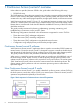
Figure 4 Using Continuous Access Journal Z with multiple storage systems When primary hosts write data to P-VOLs, the hosts add a time stamp to the data. Secondary systems check time stamps and then restore data to data volumes in chronological order (older data are restored earlier), so that data update sequence is maintained. For details on the time stamping function, see “Host I/O time stamp” (page 27).
Establishing connections between multiple secondary systems When using more than one primary system and more than one secondary system, connections among the secondary systems must be established by configuring paths and ports. To configure ports and paths between secondary systems 1. Create a command device in each of the secondary systems. 2. Configure external ports on the secondary system to be used as the supervisor DKC. 3.
Planning for previous models Continuous Access Journal Z can be used to perform remote copy operations between P9500 and XP24000/XP20000 Disk Array. Data can be copied from P9500 to XP24000/XP20000 Disk Array, or vice versa. To execute remote copy from P9500 to XP24000/XP20000 Disk Array or vice versa, set up the following: • Configure a logical path between LDKC00 of the P9500 system and the XP24000/XP20000 Disk Array. ◦ More than one XP24000/XP20000 Disk Array can be connected to LDKC00 of P9500.
Guidelines for preparing systems for Continuous Access Journal Z Use the following guidelines to insure that your P9500 systems are ready for Continuous Access Journal Z: • Identify the locations where your Continuous Access Journal Z primary and secondary data volumes will be located, then install and configure the P9500 systems. • Make sure that primary and secondary systems are configured for P9500 Remote Web Console operations. See HP StorageWorks P9000 Remote Web Console User Guide for information.
Table 11 System option modes (continued) Mode Description Mode 448 OFF: If the SVP detects a blocked path and the path does not recover within the specified period of time, the SVP assumes that an error occurred, and then splits (suspends) the mirror. NOTE: 449 The mode 448 setting is available only when mode 449 is set to OFF. Mode 449 ON: The SVP does not detect blocked paths. Mode 449 OFF: The SVP detects blocked paths and monitors the time until the mirrors get split (suspended).
Table 11 System option modes (continued) Mode Description Mode 593 ON: The multiprocessing of the communication command issued from MCU to RCU is up to 128 pairs per DKC. Mode 593 OFF: The multiprocessing of the communication command issued from MCU to RCU is up to 1024 pairs per DKC. 760 The host I/O response might decrease while the Continuous Access Journal Z pair is resynchronized.
4 Planning the data path A data path must be designed to manage your organization’s throughput to the remote site. Appropriate bandwidth, required number of ports, and the Fiber Channel data path configuration you use help insure that your update data arrives at the remote site in a time consistent with your organization’s RPO. This chapter provides instructions for calculating bandwidth and designing the data path network.
• If you cannot determine a “typical” workload, sizing should be to the average or mean workload, plus a small compensation for network overhead. In this scenario, excess data in the journals will be completely emptied to the S-VOL only occasionally. If bandwidth is sized below average write-workload, the journals never fully drain and eventually overflow resulting in the pairs suspending.
workload to abnormally high levels. It is sometimes worthwhile to review the processes that are running. After careful analysis, it may be possible to lower or even eliminate some spikes by optimizing or streamlining high-workload processes. Also, changing the timing of a process may lower workload. 3. With a base bandwidth value established, make adjustments for growth and a safety factor. • Projected growth rate accounts for the increase expected in write-workload over a 1, 2, or 3 year period.
For another perspective, you can graph the data, as shown in Figure 9 (page 42). Figure 9 60-minute rolling averages graphed over raw data 2. 3. From the spreadsheet or graph, locate the largest or highest rolling average value. This is the peak rolling average, which indicates the base amount of data that your bandwidth must be able to handle. With a base bandwidth value established, make adjustments for growth and a safety factor.
Planning ports for data transfer Updated data is transferred along the data path from the initiator and RCU target ports on the primary and secondary systems. • Initiator ports control the specific data link they are part of. • RCU target ports respond to commands from Initiator ports. • The amount of data a port can transmit is limited. Continuous Access Journal Z transfers data from the primary to the secondary storage system when the secondary storage subsystem requests data.
number of ports for a Continuous Access Journal Z system is two. To determine the required number of initiator and RCU target ports. 1. Measure IOPS for your production system. When you measure write-workload, IOPS is also provided. (See “Measuring write-workload” (page 23)). 2. Using peak IOPS and the maximum IOPS for a VSP Fibre Channel port (70,000), calculate the number of ports your Continuous Access Journal Z system requires. Peak IOPS / 70,000.
This information is illustrated in Figure 10 (page 45). Figure 10 Data path types, switches, and distances Supported data path configurations The remote data path can be configured in one of the following connection types. But for switch connection, the port should be set to Fabric on, Point-to-Point (F-port). • Direct connection, as shown in Figure 11 (page 45). Direct connection (loop only) is a direct link between the local and remote arrays.
Figure 12 Switch connection configuration Figure 13 Extender connection configuration NOTE: 46 • When an MCU and RCU are connected using switches with channel extenders, and multiple data paths are assembled, the capacity of data to be transmitted may concentrate on particular switches, depending on the configuration and the settings of switch routing. • Make sure that your channel extenders are capable of supporting remote I/O. For further details, contact your HP account team.
5 Using extended consistency groups When performing Continuous Access Journal Z operations between multiple primary and secondary storage systems, the journals must be in extended consistency groups (EXCTGs). This chapter provides information and instructions for setting up and maintaining journals in EXCTGs. Overview An EXCTG is a collection of journals in which data consistency is guaranteed.
2. Searches for the oldest time stamp from the previous step, then restores data up to that time to the secondary volumes. In the example shown in figure, the oldest time stamp is 15:00. Continuous Access Journal Z restores all data that have a time stamp 15:00 or earlier to the S-VOLs. • ◦ For Journal 1, Continuous Access Journal Z restores all data up to 15:00. ◦ For Journal 2, Continuous Access Journal Z restores all data up to 14:02.
◦ Data with the time stamp 14:03, and data with the time stamp 15:03 in journal 3. ◦ Data with the time stamp 14:04, and data with the time stamp 15:04 in journal 4. Register journals in an EXCTG When performing Continuous Access Journal Z copy operations between multiple primary and secondary storage systems, you must register the journals in an EXCTG. Prerequisite information • Set up primary and secondary EXCTGs using Business Continuity Manager prior to registering journals.
7. Enter the LDKC number. If the LDKC number is already displayed and unchangeable, you do not need to enter it. 8. Select the Controller ID. 9. Specify the LDKC number, CU number, and the LDEV number of the remote command device. If the LDKC number, CU number, and the LDEV number are already specified and unchangeable, you do not need to specify them. 10. On the lower half of the dialog box, select the journal or groups that you want to register from the JNL list on the left and click Add.
Figure 15 Multiple systems in EXCTGs Remove journals from an EXCTG You can release journals as follows: • Single, multiple, or all journals from an EXCTG or from all EXCTGs. • All journals in the storage system or LDKC. You can also forcibly remove journal that could not be removed normally. Prerequisite information • You must be logged in to the supervisor DKC to remove a journal. • You can remove journals from an EXCTG at any time, regardless of the status of the journals.
4. 5. 6. • To remove all journals from a storage system, right-click the storage system in the tree or the list. • To remove all journals in an EXCTG belonging to an LDKC, right-click the LDKC from the tree. Click Remove JNL from EXCTG in the menu that displays In the Preview list, check the journal(s) to be removed. To cancel removal of a journal, right-click and select Cancel. When satisfied, click Apply.
Figure 16 Journals that can be registered in an EXCTG when previous models (XP24000/XP20000 Disk Array) are the subordinate DKC Using EXCTGs with P9500 53
Figure 17 Journals that can and cannot be registered in an EXCTG when the previous model (XP24000/XP20000 Disk Array) is the supervisor DKC 54 Using extended consistency groups
6 Configuration operations This chapter provides the configuration tasks that will make your primary and secondary systems ready for Continuous Access Journal Z pair operations. Configuration workflow You will set up primary and secondary systems for Continuous Access Journal Z operations as follows. Check the prerequisites for each procedure. Some tasks need to be performed from both local and remote storage systems and other tasks need to be performed from the local or remote storage system. 1.
• • Before a fiber channel initiator port can be changed to target or RCU target, the following must be performed: ◦ All affected data volume pairs must be released. ◦ All logical paths must be deleted from the initiator port to the remote storage system. ◦ After logical paths are deleted, cables connecting the local system to the remote system must be removed. The number of hosts connected to a target port must be limited to 128 or fewer to avoid illegal disconnection.
Configure storage systems for Continuous Access Journal Z, define logical paths Prerequisite Information • This procedure must be performed on both primary and secondary systems. • The primary and secondary systems must already be configured for Continuous Access Journal Z operations. See “System requirements” (page 17) for more information. • The data path must be set up. See ??? for more information.
5. 6. In the S/N box, enter the remote system’s 5-digit serial number. In the LDKC box, select the remote system’s LDKC number. Enter 00 when the remote system is a P9500, XP24000/XP20000, or XP12000/XP10000 disk array. 7. 8. 9. In the Controller ID box, select the remote system’s controller ID. The controller ID for a P9500 is 6. The controller ID for an XP24000/XP20000 Disk Array is 5. The controller ID for an XP12000/XP10000 Disk Array is 4. The Path Gr. ID check box is intended for a future release.
11. The Minimum Paths box is intended for a future release. Continue to the next step. 12. RIO MIH means “remote I/O missing interrupt handler.” In the RIO MIH Time box, enter the amount of time to wait before the data transfer operation is flagged as failed by the system. The range of time is from 10 seconds to 100 seconds (15 seconds is the default). When using a 3DC cascading configuration, it recommended that RIO MIH is set at 20 seconds. 13. Click Set and display the DKC Operation window. 14.
6. In the M-R Path box, define the logical path between local and remote systems: 1. In the Port column, select a local system initiator port. 2. In the Pair-Port column, select the remote system RCU target port. This establishes a logical path with the selected initiator port. You may enter port numbers using the keyboard. You may abbreviate the number into two characters. For example, “1A” may be entered instead of “CL1-A”. Letters may be uppercase or lowercase. 7. 8. 9.
To specify number of volumes to copy concurrently 1. In Remote Web Console, select Actions > Remote Copy > Continuous Access Journal Z > Optional Operation. 2. 3. Click to change the mode from View to Modify. Right-click the value that displays under Activities in the right-side pane, then select Change System Option from the menu. The System Option dialog box displays. 4.
Register journal volumes in a journal You set up journal volumes by registering them in a journal. The procedure is provided below. Prerequisite information • A journal volume may be either a 3390 emulation volume (except for data exchange emulations and 3390-A) or it may be an OPEN-V emulation. The number of volumes registered does not have the same between the primary and secondary storage systems.
To register journal volumes 1. In Remote Web Console, select Actions > Remote Copy > Continuous Access Journal Z > Journal Operation. The Journal Operation window is displayed. 2. 3. Click to change the mode from View to Modify. To register journal volumes in an existing journal, select the journal from the Registered tree. To register journal volumes in a new journal, select the journal from the Free tree. The selected journal displays in the data pane.
5. In the Free Volumes list, select the volumes that you want to register. Each row represents a volume in the list. If you cannot find the volumes, select one of the following in the PG/CU change area: • PG, then enter a parity group number in the box, and click Show. A list of volumes in the specified parity group displays. Select the volumes that you want to register. • PG(Ext.), then enter the external parity group number in the box, and click Show.
channel (SSCH) at the main host system, and the time stamp is transferred to the primary storage system at the beginning of each I/O operation. • Local When the Local timer option is selected, the primary storage system does not acquire time stamp information from the host I/O time stamping function. • None This timer option can be selected only when the copy direction of a Continuous Access Journal Z volume pair is in reverse direction (i.e., from the secondary site to the primary site).
7 Pair operations This chapter provides procedures and prerequisite information for performing Continuous Access Journal Z copy operations. Pair operations workflow Basic Continuous Access Journal Z operations consists of the following. • Always check pair status. Each Continuous Access Journal Z operation requires the pair to be in a specific status. • Create the pair, in which the S-VOL becomes a duplicate of the P-VOL.
• If you are creating a Continuous Access Journal Z pair for delta resync, make sure all requirements are met. See “Procedure for creating a delta resync pair ” (page 136). • If this program product is running on a primary storage system or secondary storage system, stop Performance Monitor before performing the initial copy to avoid overloading with TCP/IP traffic. For details about Performance Monitor, see HP StorageWorks P9000 Performance for Open and Mainframe Systems User Guide.
5. 68 • Data for the selected volume displays in the P-VOL box. The numbers indicate the volume LDKC number, CU number, and LDEV number. • One P-VOL displays at a time, even if you selected multiple volumes for pairing. The volume with the lowest number displays first. Specify an S-VOL as follows: 1. Select the CU number and LDEV number from the two S-VOL , left to right. If you selected multiple volumes as P-VOLs, the S-VOL you specify by the list is paired with the P-VOL displayed in P-VOL.
2. If multiple pairs are created at one time, use the Select Other S-VOL(s) list to specify S-VOLs. If you selected multiple volumes as P-VOLs, you can instruct the system to automatically assign S-VOLs for the remainder of P-VOLs. Do this from the Select Other S-VOL(s) list, as follows: - Select Increment to cause Continuous Access Journal Z to add the secondary system LDEV incrementally. Your S-VOL LDEV numbers must be numbered incrementally.
by the CU configuration or a remote copy path error. Review the error, release the pair with the error, and then retry the Add Pair operation. 10. In the Error Level list, select one of the following options to take place in the event a failure occurs during this operation: • Mirror, to cause all pairs in the failed pair’s mirror to be split. Mirror is the default. • Volume, to cause only the pair that failed to be split. 11.
pair split operation. When you do this, then resync the pair, the secondary system sends the S-VOL track bitmap to the primary system to insure proper resynchronization of the pair. This S-VOL Write option is described in the pair-split procedure. To split one or more pairs 1. In Remote Web Console, select Actions > Remote Copy > Continuous Access Journal Z > Pair Operation. 2. 3. Click to change the mode from View to Modify. In the tree, select a CU group number or CU number.
9. See the Preview list in the Journal Operation window to check the settings that you have made. • If you want to modify a setting, select and right click the setting in the Preview list and then select Modify. • If you want to cancel a setting, select and right click the setting and then select Cancel. 10. Click Apply to apply the settings. If an error occurs, the error code appears in the rightmost column of the Preview list.
Restore a pair If the pair is restored, the suspended data copy from the primary data volumes to the secondary data volumes is resumed. If the delta resync pair is restored, the delta resync processing is performed. This section describes the pair resync operation. Also, the instructions are used when performing the delta resync operation. Prerequisite information • The pair resynchronizing operation is performed from the primary storage system only. • Pairs in Suspend status are resynchronized.
• If you are to use the Continuous Access Journal Z pair for delta resync operation as the master journal after a power supply error occurred at the primary storage system, first resynchronize the pair and then execute I/O operation from the host. • After the delta resync operation (when pair status has changed to Duplex), the delta resync P-VOL must be updated from the host for longer than five minutes. This is done to insure internal communications between the sites.
To be able to continue processing, do either of the following: 6. 7. 8. 9. • Ensure that the Range column displays Volume for all pairs in the same mirror. • In the Preview list, select all but one pair in the same mirror, right click the selected pairs, and then select Delete. From the Priority list, specify the scheduling order for resynchronizing selected pairs. If Range is Mirror, the Priority list is disabled.
To resynchronize a mirror 1. In Remote Web Console, select Actions > Remote Copy > Continuous Access Journal Z > Journal Operation. 2. 3. Click to change the mode from View to Modify. In the tree, expand Registered then select the desired LDKC. Journals display in the tree, Mirrors display in the right-side pane. In the list, select a pair to resume, perform the delta resync operation, or change the status from Hold(Failure) to Hold, right-click and select Mirror > Resume Pair from the menu.
volumes and asked which volume should be left offline. This can be confusing and is prone to error. If the Continuous Access Journal Z secondary data volumes and primary data volumes are connected to the same host(s), HP strongly recommend that the secondary data volumes are defined to remain offline to avoid this problem. To delete a pair or pairs 1. In Remote Web Console, select Actions > Remote Copy > Continuous Access Journal Z > Pair Operation. 2. 3. Click to change the mode from View to Modify.
8. 9. See the Preview list in the Journal Operation window to check the settings that you have made. • If you want to modify a setting, select and right click the setting in the Preview list and then select Modify. • If you want to cancel a setting, select and right click the setting and then select Cancel. Click Apply to apply the settings. If an error occurs, the error code appears in the rightmost column of the Preview list.
8 Monitoring the system Monitoring pairs, journals, and data paths should be checked frequently to insure that Continuous Access Journal Z pairs are operating correctly. Pair status should be checked before performing a Continuous Access Journal Z operation. Each operation requires specific pair status. Monitor pair activity, status Monitoring the Continuous Access Journal Z system is an ongoing operation that should be performed frequently to maintain your pairs.
Pair Status Description Suspending The pair is not synchronized. The pair is in transition from duplex or pending duplex to suspended. When the suspension is requested (by user, primary storage system, or secondary storage system), the status of all affected pairs changes to suspending. When the suspension is complete, the status changes to suspended. Deleting (releasing) This pair is not synchronized. This pair is in transition from duplex, pending duplex, or suspended to simplex.
Pair Status Description Even if the "delta resync operation" without the deferential data is executable, the pair status will change to Hold regardless of the differential data existing if the conditions of the differential data discarding are satisfied as mentioned above. To change the status of the pair to Hold, update the data in the primary disk system after the recovery from the condition of the differential data discarding.
Suspend types You can suspend a pair after the initial copy operation is complete. When you suspend a pair, the primary and secondary systems insure synchronization by completing or discarding any pending update copy operations. This depends on the Suspend Mode option that you specify in the Suspend Pair operation. A pair can also be suspended by the primary or secondary storage system.
Table 12 Suspension types (continued) Suspend type Applies to Description Initial Copy failed P-VOL, S-VOL The pair was suspended before the initial copy operation was complete. The data on the S-VOL is not identical to the data on the P-VOL. JNL Cache Overflow P-VOL, S-VOL The pair was suspended because it was highly likely that journal data will overflow. Table 13 (page 83) provides consistency statuses for suspended S-VOLs.
The tracks containing the following journal data are marked in the differential bitmap as modified and will be copied during the resume pair operation: • Journal data created by the primary system but not yet sent to the secondary system. After marking these P-VOL tracks as modified, the primary system discards these journal data. • Journal data sent to the secondary system but not acknowledged by the secondary system.
• SEQCHK Only: Specify whether to display only the volume pairs in SEQCHK status. If this check box is selected, volumes in Simplex status do not appear in the list. • Reset: Restores all options in the Display Filter dialog box to the default state. All lists show All and all check boxes are selected. • Set: Applies the settings in the Display Filter dialog box to the list. • Cancel: Discards the settings and closes the dialog box.
2. 3. In the Pair Operation window, click Export. A message appears and asks whether to save volume pair information in a file. Click OK to close the message. A dialog box appears and prompts you to save a file. 4. Enter the name of the file and then click Save. A message appears. 5. Click OK to close the message. If Subsystem or an LDKC is selected in the tree, you can abort the exporting by clicking Cancel in the dialog box that is open during the export processing.
Table 15 Fields on the Usage Monitor window (continued) Field Description Update The most recent data sample time of data on the graph. Usage Monitor Graph Remote I/O statistics and status of remote copy monitor. Select data to be graphed The usage monitor graph plots the I/O data that you specify. On the graph: • The x-axis indicates time. • The y-axis indicates the number of I/Os during the sampling period. • The legend on the right side shows the data being displayed.
5. Click Set to close the Display Item dialog box. The Usage Monitor window now shows a graph of the selected I/O statistics data for the selected LU(s). Table 16 Remote copy I/O statistics data Data type Description Host I/O Write Record Count The number of write I/Os per second Write Transfer Rate The amount of data that are written per second. The unit is kilobytes per second. Initial Copy Initial Copy Hit Rate The initial copy hit rate. The unit is percent.
Table 16 Remote copy I/O statistics data (continued) Data type Description R-JNL Average Transfer Rate The average transfer rate for journals in the secondary storage system. The unit is kilobytes per second. R-JNL Average RIO Response The remote I/O process time on the secondary storage system. The unit is milliseconds. M-JNL Data Used Rate Data usage rate for master journals. The unit is percent. Meta Data Used Rate Metadata usage rate for master journals. The unit is percent.
Status Halt Stopping Stopped Hold Hold(Failure) Blank Description An operation for splitting or deleting the mirror is in progress. An operation for splitting or deleting the mirror is in progress. An operation for splitting or deleting the mirror is finished. A Cnt Ac-J delta resync pair has been created. It is ready for the delta resync operation. An error occurred with the Cnt Ac-J pair during the delta resync operation. This is the unused journal which is not registered data volumes.
Item Description Pair-Port Port on the remote system. S/N Serial number and LDKC number of the remote system. Controller ID Controller ID and model name (in parenthesis) for the remote system. Path Gr. ID Path group ID M-R Path Type of channel interface between local and remote systems. Always displays column displays “Fibre”. Minimum Paths Minimum possible number of paths between the local and the remote systems.
9 Maintaining the system Some maintenance tasks are a response to behavior discovered during system monitoring. However, you can also change certain settings to keep the system in tune with your changing requirements. Pair maintenance—change the pair-split option You can change the option that specifies whether a pair-split operation that is triggered by pair failure is applied to all the pairs in the mirror, or only to the affected pair. This option was first set during the pair create operation.
Journal and mirror maintenance Maintaining journals and mirror consists of the following operations: • Changing journal options • Changing mirror options • Deleting journal volumes from journals • Deleting journals Change Continuous Access Journal Z options used by journals Most Continuous Access Journal Z pair operations are performed on multiple pairs. This is done using journals.
4. For Inflow Control, specify whether to restrict inflow of update I/Os to the journal volume (slows delay response to hosts). For example, you could have a 100 GB-bandwidth data path with three journals using it. If an important database is saved to a primary volume in one of the journals, with data of lesser importance in the other journals, you may decide to restrict the Inflow Control for the less important journals while not restricting control to the important journal.
9. See the Preview list in the Journal Operation window to check the settings that you have made. • If you want to modify a setting, select and right click the setting in the Preview list and then select Modify. • If you want to cancel a setting, select and right click the setting and then select Cancel. 10. Click Apply to apply the settings. If an error occurs, the error code appears in the rightmost column of the Preview list.
4. 5. 6. For Copy Pace, specify the pace for initial copy activity per volume. This field cannot be specified on the remote system. Low is the default. When specifying Medium, insure that write I/O is 10 MB/s or less per parity group. If it exceeds 10 MB/s, pairs may be suspended. When specifying High, insure that I/O will not occur. If update I/O occurs, pairs may be suspended. For Unit of Path Watch Time, specify the unit of time for Path Watch Time, minute, hour, or day.
- None: No processing and the S-VOL is not updated. 10. Click Set when finished. 11. See the Preview list in the Journal Operation window to check the settings that you have made. • If you want to modify a setting, select and right click the setting in the Preview list and then select Modify. • If you want to cancel a setting, select and right click the setting and then select Cancel. 12. Click Apply to apply the settings.
7. 8. 9. Click Set when finished. See the Preview list to check the settings that you have made. • If you want to modify a setting, select and right click the setting in the Preview list and then select Modify. • If you want to cancel a setting, select and right click the setting and then select Cancel. • If necessary, repeat steps from 2 to 6 to specify volumes that should be deleted from other journals. Click Apply to apply the settings.
To change the data-transfer threshold time 1. In Remote Web Console, select Actions > Remote Copy > Continuous Access Journal Z > DKC Operation. The DKC Operation window displays. 2. 3. Click to change the mode from View to Modify. Make sure DKC is selected in the Display box. The tree and full list on the right-side display information about the paired secondary systems. Locate the desired remote system, right-click, and select DKC Operation > Change DKC Option. The DKC Option dialog box displays.
Delete the Continuous Access Journal Z relationship You can remove the Continuous Access Journal Z pair relationship between primary and secondary storage systems. Prerequisite information • Removing the relationship between the primary and the secondary systems also removes the logical paths between them. • This operation must be performed on both the primary and secondary P9500 systems. To delete the Continuous Access Journal Z relationship 1.
When power is removed from network relay devices If power is removed from a network relay device during remote copy operations, the primary and secondary systems assume that a failure has occurred and split all pairs. Power-off storage systems intentionally This section explains what should be noted when you intentionally power off systems or network relay devices. NOTE: To intentionally power off the primary or secondary system, contact your HP account team and ask them to power off the system.
1. 2. 3. 4. 5. 6. Split all pairs that will be affected. For example, if two primary systems and one secondary system are connected to each other and you want to power off one of the primary system and the secondary system, you must split the pairs on all three systems since they are all affected. After the pairs are split, confirm that their status is Suspend at the primary system. Power off the primary system. Power off the secondary system. Power on the secondary system.
10 Disaster recovery operations This chapter provides guidelines for performing disaster recovery operations. Also included are disaster recovery procedures when Continuous Access Journal Z is configured with Continuous Access Synchronous Z and Business Copy Z. Preparing for disaster recovery The major steps for preparing for disaster recovery are: • Identify the data volumes that you wand to back up for disaster recovery. • Pair the important volumes using Continuous Access Journal Z.
1. 2. If such a pair exists, consistency in the S-VOL is suspect. Recovery with guaranteed consistency is impossible. In this case, to use the S-VOL, you must release the pair. If such a pair does not exist, execute the YKSUSPND REVERSE option on the restore journal to split the pairs. Doing this insures consistency in the S-VOL(s) and thus makes them usable. If an error occurs, consistency in the S-VOL is dubious, and recovery with guaranteed consistency is impossible.
The following procedure explains how to resume normal operations at the primary site by using Business Continuity Manager. 1. At both Continuous Access Journal Z sites, make sure that the Continuous Access Journal Z components are operational and free of failures. 2. Make sure that the pair status of P-VOLs and S-VOLs in all Continuous Access Journal Z pairs is Duplex. 3. Stop the applications at the secondary site. 4.
• “Recovering from primary site failures (when delta resync operation is performed)” (page 109) • “Recovering from failures in the primary site and the Continuous Access Synchronous Z secondary site” (page 112) • “Recovery with Business Copy Z configuration ” (page 113) Recovery in a 3DC cascade configuration If a disaster or failure occurs in the primary site of a 3DC cascade configuration, you transfer business operations to the intermediate Continuous Access Synchronous Z secondary volume (S-VOL) s
10. Use volumes in the primary site to resume your business tasks. 11. Execute the YKDELETE command onto journals that make a Continuous Access Synchronous Z pair between the intermediate site and the secondary site. The system returns to the status before the 3DC cascading configuration was set up.
4. Use Business Continuity Manager to execute the YKRESYNC REVERSE command on the Continuous Access Journal Z pair, in order to reverse the copy direction of the Continuous Access Journal Z pair. YKRESYNC is a command for re establishing a pair. 1. If reversing of the copy direction fails, create a Continuous Access Journal Z pair.
can transfer your business tasks back to the primary site after removing failures from the primary site and other locations. To transfer your business tasks back to the primary site, follow the procedure below. Business Continuity Manager is used in this procedure: 1. Stop business tasks at the Continuous Access Synchronous Z secondary site. 2.
1. 2. When the Continuous Access Journal Z pair is in Duplex status, use Business Continuity Manager to execute the YKSUSPEND Flash FORWARD command on the Continuous Access Journal Z pair. Use Business Continuity Manager to execute the YKSUSPND REVERSE command on the Continuous Access Synchronous Z pair. Continuous Access Synchronous Z pair is split and the copy operation temporarily stops. 3. 4. Use the Continuous Access Synchronous Z remote volume to resume your business tasks.
5. 6. Use the main volume in the primary site to resume your business tasks. Use Business Continuity Manager to execute the YKRESYNC FORWARD command on the Continuous Access Synchronous Z pair. The copy direction of the pair is returned to its original direction. 7. Perform delta resync operation on the volume in the Continuous Access Synchronous Z primary site. The status of the data volumes of Continuous Access Journal Z pair changes as explained in the following table.
Table 20 Pair status and operation after recovery of the primary site (continued) Invalid pair status Do the following before transferring business tasks back to the primary site Primary site: Hlde Change the status of the Hlde pair back to Hold. Cnt Ac-J Z secondary site: Hold Primary site: Simplex Cnt Ac-J Z secondary site: Hold 1. Release the pair in Hold status from the Cnt Ac-J Z secondary site. 2.
7. Use Business Continuity Manager to execute the YKMAKE command (a command for creating a pair) on the Continuous Access Synchronous Z pair.
11 Troubleshooting This chapter provides troubleshooting information. General troubleshooting General troubleshooting information for Continuous Access Journal Z. Table 21 General troubleshooting Error Corrective action Remote Web Console hangs, or Cnt Ac-J Z operations do not function properly. Make sure that the problem is not being caused by the computer or Ethernet hardware or software, and restart the computer.
Table 21 General troubleshooting (continued) Error Corrective action If a communication error occurs between the Remote Web Console computer and the SVP, see HP StorageWorks P9000 Remote Web Console User Guide for instructions. Although Monitoring Switch is set to Enable, the Because the time setting of SVP is changed, the monitoring data monitoring data is not updated. might not be updated. Set Monitoring Switch to Disable, and set Monitoring Switch to Enable again.
Table 22 Logical path troubleshooting (continued) Path status Description Corrective action port, or this path already exists. Make sure that you entered the correct secondary system S/N and path parameters (for example, primary system port, secondary system port, and controller ID). After that, delete the failed path. You may need to change the minimum paths setting or delete the secondary system in order to delete the path. After deletion finishes, add the path and the secondary system back again.
Table 22 Logical path troubleshooting (continued) Path status Description Corrective action After deletion finishes, add the path and the secondary system by using the Add Path or Add DKC command. Troubleshooting suspended pairs Troubleshooting information for user-suspended and system-suspended pairs is provided in the following two tables. Hardware failures affecting the cache memory and the shared memory of the primary or secondary system may also cause the pairs to be suspended.
Table 23 Suspended pair troubleshooting (continued) Suspend Type Applies to Description Corrective Action Restart the initial copy operation by using the Add Pair dialog box. MCU P/S-OFF S-VOL The primary system suspended all Cnt Ac-J None. The primary system automatically Z pairs because it was powered off. restores these Cnt Ac-J Z pairs when it is powered on.
Here are some guidelines for troubleshooting the Remote Web Console computer: • Check the cabling and the LAN. Verify that both the computer and LAN cabling are firmly attached. • Reboot the computer. Close any programs that are not responding. If necessary, reboot the computer and restart the Remote Web Console program. • Check error codes. For detailed information about error codes displayed on Remote Web Console computers, see HP StorageWorks P9000 Remote Web Console Messages. • Check error codes.
Figure 19 Typical SIM with reference code and SIM type NOTE: The SIMs shown below are reported to the host, except 21 81. The following table shows SIMs reference codes, and provides useful information for identifying issues and determining the system experiencing the problem. All SIMs are reported to the host, except 21 80.
Table 25 SIM reference codes, types, and descriptions (continued) Reference code Byte 22 Severity Description System generating the SVP log SIM file Byte 23 A failure has been detected in the secondary system. DC 9X Serious A volume being used by P-VOL of the Cnt Yes, repeatedly. Ac-J Z pair for delta resync operation has been suspended. Primary storage system A failure has been detected in the primary storage system.
Clearing SIMs SIMs that are sent to hosts are also saved in the storage system. The following procedure clears all SIMs from both mainframe and open systems: CAUTION: You cannot delete only Continuous Access Journal Z SIMs. If you follow the procedure below to clear all Continuous Access Journal Z SIMs, Continuous Access Journal SIMs are also cleared at the same time. The SIMs of the entire storage system are cleared. To clear all SIMs 122 1.
12 Support and other resources Contacting HP For worldwide technical support information, see the HP support website: http://www.hp.
HP websites For additional information, see the following HP websites: • http://www.hp.com • http://www.hp.com/go/storage • http://www.hp.com/service_locator • http://www.hp.com/support/manuals • http://www.hp.com/support/downloads • http://www.hp.
Table 26 Document conventions (continued) Convention Element Monospace text • File and directory names • System output • Code • Commands, their arguments, and argument values Monospace, italic text • Code variables • Command variables Monospace, bold text WARNING! CAUTION: IMPORTANT: NOTE: TIP: Emphasized monospace text Indicates that failure to follow directions could result in bodily harm or death. Indicates that failure to follow directions could result in damage to equipment or data.
A Sharing Continuous Access Journal Z volumes This appendix discusses non-Continuous Access Journal Z volumes that can be shared as Continuous Access Journal Z volumes. It discusses the volumes of several features that can be used in full or limited ways with Continuous Access Journal Z. Continuous Access Synchronous Z and Business Copy Z volumes can be used extensively with Continuous Access Journal Z.
Table 27 Volume types that can be shared with Continuous Access Journal Z (continued) Functions and volumes Can the volumes be used as Can the volumes be used as Can the volumes be used as P-VOLs? S-VOLs? journal volumes? Source volume (when volume migration is in progress) Yes. Note that volume migration stops when the source volume is used as a P-VOL. Yes. Note that volume migration stops when the source volume is used as a S-VOL.
Table 27 Volume types that can be shared with Continuous Access Journal Z (continued) Functions and volumes Can the volumes be used as Can the volumes be used as Can the volumes be used as P-VOLs? S-VOLs? journal volumes? *5: First, create a Cnt Ac-J Z pair and change its status to Suspend. Then, create a Compatible FlashCopy pair by specifying the Cnt Ac-J Z P-VOL as T-VOL.
For further information on Performance Monitor, see HP StorageWorks P9000 Performance for Open and Mainframe Systems User Guide. Data Retention You can create a Continuous Access Journal pair by using volumes to which access attribute is assigned by Data Retention. However, you cannot specify a volume with "S-VOL Disable" attribute as the secondary data volume of the pair. The following table shows pair status and availability of Data Retention operation.
B Continuous Access Journal Z configurations with Continuous Access Synchronous Z Continuous Access Journal Z and Continuous Access Synchronous Z can share the same data volumes. Using Continuous Access Journal Z and Continuous Access Synchronous Z can extend disaster recovery options to a third data center. This appendix provides planning formation for sharing Continuous Access Journal Z volumes with Continuous Access Synchronous Z.
The host issues an update to the Continuous Access Synchronous Z primary volume (M-VOL), which is copied synchronously to the R-VOL. The Continuous Access Journal Z system copies the synchronous S-VOL data to the Continuous Access Journal Z remote site. Data in the Continuous Access Journal Z S-VOL is an asynchronous copy of the Continuous Access Synchronous Z M-VOL. Depending on RPO and bandwidth, Continuous Access Journal Z S-VOL data can be very close to P-VOL data.
• When the Continuous Access Synchronous Z pair is recovered, the Continuous Access Journal Z pair in Duplex or Pending status is automatically split by the system. • The fence level of the Continuous Access Synchronous Z M-VOL must be Data. • 3DC Cascade is not supported for multiple primary and secondary systems. • The response time for host I/Os will be the response time for Continuous Access Synchronous Z operation plus the creation time of journal data in the intermediate site.
The benefit of this configuration is that it provides a third copy of the data, helping to insure that business can continue in the event of a failure at the other two sites. Failure recovery occurs as follows: • If a failure occurs in the M-VOL, business is resumed using the Continuous Access Synchronous Z R-VOL. When the failure is corrected at the primary site, business tasks are transferred back to the primary site.
3. When Continuous Access Synchronous Z pair status is Duplex, create the Continuous Access Journal Z pair on the primary system. The mirror ID must be set between 1 and 3. Delta resync configuration In a Continuous Access Journal Z delta resync configuration, you create a second Continuous Access Journal Z pair in a 3DC multitarget. The pair is created using the Continuous Access Synchronous Z secondary volume (R-VOL) and the Continuous Access Journal Z S-VOL, as illustrated in the following.
Prerequisite information for creating the delta resync pair • A Continuous Access Journal Z delta resync pair is created in a 3DC Multitarget configuration only. • Do not include the 3DC Multi-target configuration in the system that consists of multiple primary and secondary storage systems. • Continuous Access Journal Z delta resync M-VOL = Continuous Access Synchronous Z secondary volume (R-VOL) at the intermediate site.
If any Continuous Access Journal Z pair in the journal group does not meet the above requirements, an error occurs and delta resync operation will fail, even if the specified Continuous Access Journal Z pair meets the requirements.
2. 3. 4.
Figure 24 Remote command device configuration for delta resync When mapping to remote command devices on each site is complete, you must assign mirror IDs to the remote command devices. This is required to enable communication for delta resync operations. Assign mirrors to remote command devices The use of mirrors with remote command devices allows you to determine whether the delta resync operation can be performed.
- Assign the mirror ID used for the Continuous Access Journal Z 3DC multitarget pair to the remote command device that is mapped to on the remote site. • On the intermediate site: - Assign mirror ID 00 to the remote command device that is mapped to on the primary site. - Assign the mirror ID used for the Continuous Access Journal Z delta resync pair to the remote command device that is mapped to on the remote site.
Perform the delta resync operation The delta resync operation is performed during disaster recovery. This operation copies differential data from the Continuous Access Synchronous Z R-VOL to the Continuous Access Journal Z S-VOL. The delta resync operation is part of the Resume Pair operation. Follow instructions in “Restore a pair” (page 73) to execute delta resync.
C Continuous Access Journal Z configurations with Business Copy Z Continuous Access Journal Z and Business Copy Z can share the same data volumes to provide multiple copies of data, at both the primary and secondary sites. This appendix provides configurations and information for using Business Copy Z with Continuous Access Journal Z. For details about Business Copy Z, see HP StorageWorks P9000 Business Copy for Mainframe Systems User Guide.
Figure 25 Shared Continuous Access Journal Z and Business Copy Z primary volume Business Continuity Manager allows you to set the starting time of the backup copy to journals. In the above configuration, if you set the starting time of the backup copy, the write operations to the P-VOL up to that time are backed up to the S-VOL. If the above configuration is used in multiple journal volumes in multiple storage systems, you can set the same starting time of the backup copy to all the journals.
Figure 27 Shared Continuous Access Journal Z primary volume and secondary volume with Business Copy Z primary volumes Configurations with Business Copy Z secondary volumes The following figure shows a Business Copy Z primary volume used as the production volume. A remote Continuous Access Journal Z backup copy is made of the Business Copy Z secondary volume. The Business Copy Z pair must be in Suspend status (Split) to perform the Continuous Access Journal Z operation.
Check pair status for shared volumes as follows: • For Continuous Access Journal Z, check status of the primary volume or secondary volume. • For Business Copy Z, check status of the primary volume. Remote Web Console shows the port, GID, LUN, LDEV ID and Business Copy Z pair status of all secondary volumes associated with a primary volume. Business Copy Z supports multiple secondary volumes for each primary volume.
2. 3. 4. Among the Continuous Access Journal Z restore journals, the journal data created before the split time is restored to Continuous Access Journal Z S-VOLs (Business Copy Z S-VOLs). When Continuous Access Journal Z detects the journal data from the restore journal that has the time stamp later than the split time, restore operations are suspended. After that, split operations are executed on Business Copy Z pairs that are in conjunction with Continuous Access Journal Z S-VOL.
If you use the At-Time Split function when combining Continuous Access Journal Z with Business Copy Z, note the following: 146 • The specified split time is enabled even after the split operation has been executed on Business Copy Z pair. When you execute split operation again on Business Copy Z consistency group that has been split before, specify the split time after deleting the split time registered before.
D Continuous Access Journal Z GUI reference This appendix describes the Continuous Access Journal Z windows, dialog boxes, fields, and behaviors in Remote Web Console. Journal Operation window This window lets you view details about journals and volumes. Information on the Journal Operation window will be updated when you do one of the following: • Click Apply. • Select another tab, and then reselect the Journal Operation tab. • Click File > Refresh on the menu bar.
• “Resynchronize a mirror” (page 75) • “Delete pair volumes from a mirror” (page 78) Item Description Tree Lists journals in the local storage system. The tree shows journals used with Continuous Access Journal, though not Continuous Access Journal Z. • Journals: This item is located at the top of the tree. When selected, the Journal Operation list shows journals in the local storage system.
Item Description Journal (continued) • Status: Indicates the status of a mirror in the local storage system. - Initial: A mirror in initial status. Journal volumes are registered in this journal, but no data volumes (P-VOLs or S-VOLs) are registered in this journal. If a Cnt Ac-J Z pair is created, data volumes are registered in a mirror and the status of the mirror changes to Active. - Active: Either of the following: Initial copy is in progress. The P-VOL and the S-VOL are not synchronized.
Item Description When the Preview list shows changes that have been made, you can perform only the same type of operation that you have been doing and cannot perform most of other operations (you can only view detailed information about journals even when the Preview list shows changes).
Item Description Journal (LDKC) The number of a journal and the LDKC number. The LDKC number is enclosed in the parentheses following the number of a journal, for example, 01 (00). A journal number ending in [&], indicates the journal is in a 2DC configuration, for example, 01 (00) [&]. Attribute The attribute of the journal. When one journal uses multiple mirror IDs, Attribute indicates the attribute of the data volume in the journal whose mirror ID is not Hold, Holding, or Hold(Failure).
Item Description Caution: This setting does not take effect on master journals. However, if the Business Continuity Manager YKRESYNC REVERSE command is used to change a master journal into a restore journal, this setting affect the journal. If you set Use, this setting only takes effect on the journal volumes of RAID-5 or RAID-6 that are in the journal. For external volumes, non RAID-5 journal volumes, and non RAID-6 journal volumes, Use works the same as Not Use.
Item Description [None]: No processing takes place when delta resync operation cannot be performed. Therefore, the S-VOL will not be updated. - Speed of Line: The line speed (in megabits per second) of data transfer. One of the following appears: 256, 100, or 10. This setting does not take effect on master journals. However, if the Business Continuity Manager YKRESYNC REVERSE command is used to change a master journal into a restore journal, this setting takes effect on the journal.
Item Description Set Applies the settings in the dialog box to the Journal Operation window Cancel Cancels the settings and closes the dialog box. Change Mirror Option dialog box This dialog box lets you change the options of a mirror. Item Description Inflow Control Restrict inflow of update data to the journal volume. Yes restricts inflow, No does not restrict.
Item Description Delta resync Failure Sets the processing that takes place when the delta resync operation cannot be performed—entire P-VOL is copied or no processing (S-VOL not updated). Set Applies the settings in the dialog box to the Journal Operation window Cancel Cancels the settings and closes the dialog box. Edit Journal Volumes dialog box This dialog box lets you register or delete journal volumes from a journal.
Item Description PG/CU change Sets which Free volumes to populate the list with: • PG: Shows volumes belonging to a parity group. • PG(Ext.): Shows external volumes belonging to a parity group. • CU: Shows volumes belonging to a CU. • Box: Where you either enter a PG and PG(Ext.) parity group number or select a CU. Timer Type The type of clock used for consistency time. System: The system clock of the mainframe host is used. Local: The system clock is not used.
• “Restore a pair” (page 73) • “Delete a pair ” (page 76) Item Description Tree Lists LDKCs of the local storage system, with CU groups displaying under the LDKC. The CU images appear under the CU groups. Selecting a CU group or a CU image lists the volumes for the CU group or image. You can select only one CU group or image at one time and cannot select two or more simultaneously.
Item Description Deleting: The P-VOL and the S-VOL are not synchronized. This pair is in transition from the Pending, Duplex, or Suspend status to Simplex status. • Sub:Indicates one of the following statuses: SEQCHK: When the S-VOL was using the system timer, the volume received update data without a time stamp from the host computer. Mirror: The pair is split. The consistency time for the S-VOL matches the consistency time for the journal. Volume: The pair is split.
Item Description Pair Operation (continued) • Pair JNL: The journal number for the remote storage system. This column is blank if the volume in the local storage system is neither a P-VOL nor a S-VOL. • Err Lv.: The range of pair split on error. Mirror: If an error occurs with this pair, all the pairs in the mirror where this pair belongs will be split. Volume: If an error occurs with this pair, only this pair will be split. • Sync.
Item Description When the Preview list shows changes that have been made, you can perform only the same type of operation that you have been doing and cannot perform most of other operations (you can only view detailed information about pairs even when the Preview list shows changes). For example, if you are trying to release pairs and the Preview list shows the pairs that you want to release, you are unable to perform any other operations; for example, you are unable to split pairs and restore pairs.
Item Description Status Shows pair status. For status definitions, see “Pair status definitions” (page 79). If the pair is split (or suspended), Status also shows the suspend type. If the pair is waiting for initial copy, Status shows the word “Queuing”. A pair’s status varies between the P-VOL and S-VOL for short periods when the secondary system changes the pair’s status. The secondary system can change only the S-VOL’s status.
Item Description P-VOL, S-V0L Show information about the pair volume. • The first line shows the LDKC number, the CU number, and the LDEV number. If the P-VOL exists in the local storage system, the first line also displays the CLPR number and the CLPR name. • The second line shows the device emulation type. • The third line shows the volume capacity. • A device ID ending in X (for example, 00:00:3C X) indicates the LDEV is a Thin Provisioning virtual volume.
Item Description • Timer Type, the type of timer used by the data volume: - System—the system clock of the mainframe host is used. - Local—the system clock of the SVP is used. - None—no system clock is used, the SVP time is used. • SEQCHK displays if the S-VOL uses the system timer and receives update data without time stamp from the host computer. Refresh the Pair Operation window after this window is closed When clicked, the Pair Operation window refreshes when it is redisplayed.
Item Description P-VOL Indicates a P-VOL. The numbers are the LDKC number, the CU number and the LDEV number of the P-VOL. This column displays only one P-VOL even when two or more P-VOLs are selected in the Pair Operation window. P-VOL only displays the P-VOL that has the smallest volume number. An LDEV number ending with # indicates the volume is an external volume. For detailed information about external volumes, see HP StorageWorks P9000 External Storage for Open and Mainframe Systems User Guide.
Item Description Select Other S-VOL(s) Specify how Cnt Ac-J Z automatically assigns S-VOLs if two or more P-VOLs are selected in the Pair Operation window. • Increment: Cnt Ac-J Z increments volume numbers of the resulting S-VOLs one by one. For example, if you create 3 pairs and specify 11 on the LDEV of P-VOL, the LDEVs on the secondary system are incremented at 11, 12, and 13. • Input Next: You can specify a volume number for each P-VOL.
Item Description CFW Specify whether to copy cache fast write data to the S-VOL. The default is Only P-VOL. • Only P-VOL: Does not copy cache fast write data to the S-VOL. • Copy to S-VOL: Copies cache fast write data to the S-VOL. M-JNL Information Displays information about the master journal. • Current Mirror(s): Indicates the number of mirrors registered in the master journal. • Total Mirror(s): Indicates the sum of the following: (1) The number of mirrors registered in the master journal.
Item Description Suspend Mode Specify how to deal with update data that has not been copied to the S-VOL. The default is Flush: • Flush: When you split the pair, update data is copied to the S-VOL. When the secondary storage system receives a request for splitting a pair, all the journal data (that is, update data) that the pair retains is written to the S-VOL. After that, the status of the pair changes from Suspending to Suspend if the pair does not retain any journal data for a certain period of time.
Item Description Resync Mode Indicates the processing after recovery of the pairs. • Normal: Split pair whose status is Suspend is recovered. • Delta: Delta resync operation is performed. • Return to standby: The status of pairs is recovered from Hlde to Hold. Error Level Specify the range used for splitting a pair when a failure occurs. If Range is Mirror, you cannot change the Error Level option. • Mirror: If a failure occurs with a pair, all pairs in the mirror where the pair belongs are split.
Item Description In the Preview list, select one pair in one mirror, and then other pairs in the mirror is excluded. Delete Mode Specify whether to release the pair(s) forcibly. When the status of the pair(s) to be released is Simplex or Deleting, the default setting is Force. Otherwise, the default setting is Normal: • Force: The pair(s) is forcibly be released even if the primary storage system is unable to communicate with the secondary storage system.
Item Description Journal The journal to display. All shows all journals. Mirror Mirrors to display. All shows all mirrors. P-VOL/S-VOL The type of pair volume to display, P-VOL or S-VOL. CLPR The cache logical partition to display. CLPRs are used to segment the cache that is assigned to parity groups. If you select All, all CLPRs display in the list Internal/External VOL Whether internal volumes or external volumes display.
• Close the DKC Status window. • Click File > Refresh on the menu bar. • Select Modify mode when you are in View mode.
Item Description Preview Shows changes made in the window before they are applied to the system. You can modify or delete by right-clicking on an item. When the information is correct, click Apply. Operation Indicates the operation in progress in the DKC Operation window. Remote Systems Information The list area on the DKC Operation window shows information about the remote system when you select DKC in the Display box and the LDKC in the tree.
Logical Path Information The list area on the DKC Operation window shows information about logical paths between ports on the local and remote systems when you select DKC in the Display box and the remote system in the tree. Item Description Path Gr. ID The path group ID. The icon indicates the status of the path: The logical path is in normal status A failure occurred at the logical path. M-R Path The channel type of the logical paths between the local storage system and the remote storage system.
Item Description Tree The channel adapters and ports on the local storage system. The following information appears to the right of the icon: Channel adapter (Fiber Channel interface) Target port RCU target port Initiator port External port Port in initiator/external mix mode Operation The ports on the local storage system: • Port: Port number. • Attribute: Port attribute (i.e., initiator, target, RCU target, external, or initiator/external) • PCB Mode: Mode of the port.
Item Description No Number of the row. Path Status Status of a logical path. • Normal. The path is established and ready to use for copy operations. • In Progress. An operation for configuring or deleting the path is in progress. • Initialization Failed. An error occurred when the connection between local and remote systems was initializing. The probable causes are: - No cable is connected to the local system. - No cable is connected to the remote system.
Item Description Port Port on the local system. Pair-Port Port on the remote system. S/N Serial number and LDKC number of the remote system. Controller ID Controller ID and model name (in parenthesis) for the remote system. Path Gr. ID Path group ID M-R Path Type of channel interface between local and remote systems. Always displays column displays “Fibre”. Minimum Paths Minimum possible number of paths between the local and the remote systems.
Item Description S/N Remote system 5-digit serial number. LDKC Remote system LDKC number, 00 for XP24000/XP20000 Disk Array. Controller ID Remote system controller ID, 6 for P9500, 5 for XP24000/XP20000 Disk Array, 4 for XP12000 Disk Array/XP10000 Disk Array. Path Gr ID Field intended for a future release. M-R Path Logical path between local and remote systems. • Port: local system initiator port. • Pair-Port: remote system RCU target port. Option Opens DKC Option dialog box.
Item Description Minimum Paths Field intended for a future release. RIO MIH Time Amount of time the system waits before a data transfer operation is flagged as failed. The range is from 10 seconds to 100 seconds; 15 seconds is the default. Usage Monitor window This window lets you monitor remote copy operations data and I/O statistics. See “Monitor copy operations data, I/O ” (page 86) for complete information. Field Description Monitoring Switch • Enable: Monitoring is on. Graph displays.
Use this window to export pair operations history. Item Description Status The current status of operation history: • No history file exists: Operation history does not exist. • Reading a history file failed: An attempt to read operation history failed. • Updating ... n (%): Updating of operation history is now in progress, where "n (%)" indicates the progress (in %). When the updating is in progress, the checking process automatically continues until updating finishes.
Item Description Provisioning virtual volume. For details on a virtual volume, see HP StorageWorks P9000 Provisioning for Open Systems User Guide. • Paired VOL: The volume paired with the manipulated volume. This volume is located in the remote storage system. This number indicates LDKC:CU:LDEV (the LDKC number, the CU number, and the LDEV number). • EXCTG: The EXCTG number. This column is blank if the volume does not belong to any EXCTG.
Operation Displayed Description Status Change by MCU(Suspend to Simplex) The status of the pair was changed from Suspend to Simplex because of an operation from the primary system. Status Change by MCU(Suspend to Pending) The status of the pair was changed from Suspend to Pending because of an operation from the primary system. Status Change by RCU(Suspend Pair Start) The status of the pair was changed because an operation for splitting a pair started at the secondary system.
• If a failure occurred with two or more pairs at the same time, the number of pairs showing Suspend Pair(Failure) or Ready for Delta resync(Failure) may not match the actual number of pairs in which the failure occurs. • The copy time might not be shown in the Copy Time column, even though Add Pair Complete or Resume Pair Complete is shown in the Operation column.
Item Description Tree Provides access to the storage system. Select Subsystem. Activities Storage system option settings. Preview When you change settings in the Optional Operation window, the Preview list shows the changes. Here, the changes have not been applied to the storage system. Clicking Apply applies the changes to the storage system. Operation Indicates the operation that will occur when you click Apply. • Change System Option: Change storage system options.
Use the EXCTG Operation window to: • “Register journals in an EXCTG ” (page 49) • “Split, restore, release pairs in an EXCTG ” (page 50) • “Remove journals from an EXCTG ” (page 51) • “Forcibly remove journals” (page 52) • “View the EXCTG List ” (page 185). • “View Storage Systems in an EXCTG ” (page 186). • “View journals in an EXCTG ” (page 186). • “Add Journal” (page 187) Item Description Tree Lists EXCTGs.
Item Description Remove Journal from EXCTG: Delete journals from an EXCTG • Preview: The number to the left of the slash (/) indicates the number of items (i.e., rows) appearing in the Preview list. The number to the right of the slash indicates the maximum number of items (i.e., rows) that can appear in the Preview list. Apply Applies settings in the Preview list to the storage system. Cancel Cancels the settings in the Preview list.
Item Description • Underflow or Overflow appears in this column if an invalid time stamp is detected. If Underflow appears, the time stamp is below the allowable range. If Overflow appears, the time stamp is above the allowable range. • The consistency time is valid only for the updates on the Cnt Ac-J Z pairs in Duplex status. When the data of the Cnt Ac-J Z pair that is in other than Duplex status is updated, the consistency time is not assured.
Item Description : A restore journal. Status Status of a journal. JNL Journal numbers. A journal number is a two-digit hexadecimal number. To determine if a pair in an Active journal is split, navigate to the Journal Operation window and check the status of the journal. If a pair is split, the Journal Operation window displays the status of the journal as Active(Warning).
Item Description Mirror ID Specify a mirror ID. Num of JNLs The number of journals: • Current: The number of journals already registered in the storage system. • Total in DKC: The number of journals in the storage system after journals are registered or removed. • Total in EXCTG: The number of journals in the extended consistency group after journals are registered or removed.
Glossary BC P9000 or XP Business Copy. An HP application that provides volume-level, point-in-time copies in the disk array. BC Z The version of Business Copy that supports mainframe volumes. bit The basic unit of data in a binary numbering system (binary digit), represented by a 0 or a 1. Eight bits equals one byte. CCHH Cylinder, cylinder, head, head. CLI Command-line interface. An interface comprised of various commands which are used to control operating system responses.
P-VOL Primary volume. parity group A set of hard disk drives that have the same capacity and that are treated as one group. A parity group contains both user data and parity information, which enables user data to be accessed if one or more drives in the group is not available. path A path is created by associating a port, a target, and a LUN ID with one or more LDEVs. Also known as a LUN. PCB Printed circuit board. PiT Point-in-time.
Index Symbols 3 data center cascade configuration, 130 A adding logical paths, 57 B basic operation, 8 BCM specifications, 19 business requirements, assessing, 22 C Cache and Nonvolatile Storage (NVS), 18 calculating bandwidth, 40 collecting write-workload data, 23 command device, 21 component, 9 Configuration workflow, 55 consistency groups with multiple systems, 19 contacting HP, 123 conventions document, 124 storage capacity values, 124 text symbols, 125 copy operations , 13 copying data to primary si
planning, 25 specifications, 19 L latency, 42 logical paths additional, 59 deleting, 99 monitoring;monitoring:logical paths, 90 troubleshooting;troubleshooting:logical paths, 115 M maintaining the system, 92 MCU, RCU, 11 measuring write-workload, 23 mirror ID explained, 12 mirrors changing options, 95 splitting, 72 monitoring pair, 79 moving operations to S-VOL;S-VOL taking over host operations, 103 multiple system, 32 deleting pairs from a mirror, 78 delta resync - create the pair, 135 delta resync - pe
switch connection, graphic, 46 symbols in text, 125 system option modes, planning, 36 System requirements, 17 T target port, 43 technical support HP, 123 service locator website, 124 text symbols, 125 time stamp, 27 typographic conventions, 124 V VOLSER, requirements, 28 volume max capacity, 27 W websites HP , 124 HP Subscriber's Choice for Business, 123 product manuals, 123 193