
HP P9000 Business Continuity Manager User Guide


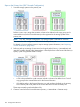

A 3DC Cascade configuration example
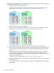
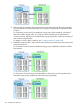
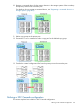
Figure 77 (page 136) shows an example of a 3DC Cascade configuration.
Figure 77 Example of a 3DC Cascade Configuration
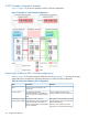
Preparing the hardware (3DC Cascade configuration)
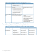
Table 33 (page 136) lists the prerequisite hardware and Table 34 (page 137) provides the storage
system settings for using Business Continuity Manager in a 3DC Cascade configuration.
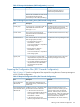
Table 33 Prerequisite Hardware (3DC Configuration)
RemarksDescriptionItem
–One unit each for the primary and
remote sites.
Host
Only a configuration that has one
storage system for each site is allowed.
One XP12000/XP10000,
XP24000/XP20000, or P9500 Disk
Storage system
Array on each site (3 storage systems in
total)
The system can only operate with a path
from the primary site to the intermediate
site (forward direction).
Between the primary site and
intermediate site: Bidirectional physical
path connected by a FCP cable. (A
Link between storage
systems (physical path)
However, when operations from the
remote site or use of the Reverse Resync
reverse direction path is recommended
but not mandatory.)
136 Configuration Definitions