HP P9000 for Business Continuity Manager Software Reference Guide Abstract This manual is a reference guide to the following program products, known collectively as Business Continuity Manager: HP P9000 for Business Continuity Manager Basic and HP P9000 for Business Continuity Manager Continuous Access Journal 4x4 Extended CTG.
© Copyright 2007, 2011 Hewlett-Packard Development Company, L.P. Confidential computer software. Valid license from HP required for possession, use or copying. Consistent with FAR 12.211 and 12.212, Commercial Computer Software, Computer Software Documentation, and Technical Data for Commercial Items are licensed to the U.S. Government under vendor's standard commercial license. The information contained herein is subject to change without notice.
Contents 1 ISPF Panels................................................................................................8 Overview of ISPF Panels............................................................................................................8 ISPF Panel System................................................................................................................9 Operating Procedures........................................................................................................
Define Command Device Panel.......................................................................................51 Sort the Define Command Device Panel...........................................................................52 Edit APID Panel.............................................................................................................53 Entire Route Information Panel.........................................................................................53 Add Route Entry Panel...........
CAJ Copy Group Performance Statistics Panel.................................................................125 Sort CAJ Copy Group Statistics Panel.............................................................................128 Copy Group Pair Status Panel.......................................................................................129 Sort the Copy Group Pairs Status Panel..........................................................................132 Volume Query Information (BC) Panel.............
YKFREEZE Command.......................................................................................................213 YKH2B Command...........................................................................................................214 YKIMPORT Command......................................................................................................216 YKINSCHK Command......................................................................................................217 YKLOAD Command.......
REXX Variables Updated by YKQUERY Command with the TO Parameter Specified..................345 REXX Variables Updated by the YKEWAIT Command with the TO Parameter Specified..............348 CSV Files Used by the Copy Group Definition File Generation Function........................................349 CSF File Dataset Formats and Disk Requirements..................................................................349 Specification Format for CSV Files............................................................
1 ISPF Panels This chapter explains how to move between ISPF panels and perform operations on them, and the nature and function of displayed items.
overview of ISPF panels. Note that the following explanations assume the default values for the PF key numbers. ISPF Panel System Figure 1 (page 9) and Figure 2 (page 10) show the panel structure beginning with the main menu. As the panel system illustration suggests, there are multiple levels of panels. Tertiary panels are accessed through secondary panels.
Figure 2 ISPF Panel System (2 of 2) Operating Procedures There is no restriction on the case and type of characters entered. The maximum length of the entered characters is determined by the length of the input fields. A validation check takes place after input. After entering the data, confirm the entry by pressing Enter.
• F12=Cancel: Cancels the process • F17=DispConf: Displays the settings information Panel Scrolling If there are more rows than can be displayed at once within the panel, F7=Backward and F8=Forward can be used to scroll the screen. The last row of table data is marked Bottom of data. In panels that display lists, you can use the Scroll line to specify the amount that will be scrolled. Command Line Commands This section describes the commands that can be used on the command line.
Table 1 SELECT Parameters (continued) Parameter Explanation character-string* *character-string To specify a field value that contains spaces or commas (,), enclose the specified field value in single quotation marks ('). Asterisk (*) Used to select all rows in a list. 'value-1':'value-2' Specifies a range of field values. This pattern can be used only for DEVN, PDEVN, SDEVN, and VOLSER fields. (VOLSER is in EBCDIC code order.
field-name For details about the specifiable field names and sort order, see the descriptions for each panel. If you omit the field name, a pop-up panel will appear and you can specify the sort key. NOTE: If you specify a field name, you cannot sort on multiple items. If you specify an invalid field name, a pop-up panel for specifying the sort key is displayed. SCANPAIR Command Function The SCANPAIR command displays the Scan Copy Pair Inside Storage System panel that scans volumes of PPRC copy pairs.
Table 2 Commands that Can Be Used on the Command Line (continued) Panel Name Command Name LOCATE SELECT SORT SCANPAIR ERRCODE Pair Selection List (Secondary) — Y — — Y Path Set Detail — — Y1 — Y Path Set Status — — Y1 — Y Path Set Status of Copy Group Pair — — Y1 — Y Setting Information — — — — — Hitachi TrueCopy™ Asynchronous for Mainframe Copy Group Performance Statistics Y — Y — Y Continuous Access Journal for Mainframe Copy Group Performance Statistics Y — Y
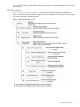
Common Displays Among Panels This section describes the common displays among panels. Panel Help Information Help information for each panel is displayed when the cursor is positioned on each panel field and F1=Help is pressed. Figure 3 (page 15) shows an example of the Help panel. Figure 3 Help Panel Setting Information Panel A Setting Information panel is displayed when F17=DispConf is pressed in the panels where F17=DispConf appears. Figure 4 (page 15) shows the Setting Information panel.
Table 3 Contents of the Setting Information Panel (continued) Item Description ISPF Log Max The maximum number of messages (message structures) that are output to the ISPF log when a command is executed Remote DKC Function Displays whether the remote DKC control function is applied: • Y: The Remote DKC Control Function is being used. • N: The Remote DKC Control Function is not being used.
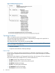
If you place the cursor on an error code that is within the displayed message, and then press the F5=ErrCode key or execute the ERRCODE command, details for that error code will be displayed in the Error Code Help panel. For details on the Error Code Help panel, see “Error Code Help Panel” (page 18). Note that when an error code is split it and spans two rows, details for the error code cannot be displayed, even if you place the cursor on the error code.
Figure 6 Cancellation Warning Panel When you press the Enter key, the configuration file is not created or updated. If F12=Cancel is pressed, the panel is displayed, in which you can create or update the configuration file. Error Code Help Panel Executing the ERRCODE command displays the Error Code Help panel. If you enter an error code on this panel, you can view the details for that error code. For details about the ERRCODE command, see “ERRCODE Command” (page 13).
Table 5 Items in the Error Code Help Panel Item Description Error code For specifying or displaying an error code whose details will be displayed. Error details Displays the error code details.
Capacity Warning Panel When refreshing a copy group definition file, if the file contains a copy pair whose P-VOL and S-VOL are different capacities, or the file contains a copy pair for which the capacity of the P-VOL, S-VOL, or both cannot be acquired, then a Capacity Warning panel is displayed, asking you whether you want to refresh the file. Figure 9 (page 20) shows the Capacity Warning panel. Figure 9 Capacity Warning Panel Pressing the Enter key transitions to the Copy Group Detail Definition panel.
Figure 10 Panel Transitions from the Main Menu Pressing the F6=Sort key sorts items on the panel. To display the Main Menu panel: 1. Select 6 Command from the ISPF menu. 2. Enter YKSTART.
Installation Verification Summary panel If any of the following conditions are met, the system assumes that the installation of Business Continuity Manager did not complete and the Installation Verification Summary panel is displayed: • No profile for referencing or operations has been specified for the RACF security setting. • No user SVC has been registered. • A user SVC version is enabled that cannot be used with the version of Business Continuity Manager being installed.
Table 6 Contents of the Main Menu Item Description 0 Installation Verification Verifies the environment settings.
Table 7 Items in the Installation Verification Summary Panel Item Description 1 Security Setting Status of the RACF security setting • OK: A profile for referencing or operations has been specified. • FAULTY: No profile for referencing or operations has been specified. 2 User SVC Routine Status of the user SVC setting • OK: The user SVC version is one that can be used with the version of the Business Continuity Manager instance that is running.
User SVC Information Panel When you select 2 User SVC Routine from the Installation Verification Summary panel, the User SVC Information panel is displayed. The User SVC Information panel displays the user SVC setting information. Figure 14 (page 25) shows the User SVC Information panel.
Table 9 (page 26) lists and describes the items in the User SVC Information panel. Table 9 Items in the User SVC Information Panel Item Description Version of User SVC for this program The version of the user SVC, which can be used with the Business Continuity Manager instance that is running. If the value shown for the Version of the Current User SVC is less than the value of the Version required for the User SVC for this program, a newer version of the user SVC must be registered.
• The setting for use of the Remote DKC Control Function or the route list ID • The parameters for the YKWATCH command, which monitors volume status, and the JCL for background jobs The Set Defaults panel is shown in Figure 15 (page 27) (values in the figure are samples only). Figure 15 Set Defaults Panel Table 10 (page 27) describes the items in the Set Defaults panel.
Table 10 Contents of the Set Defaults Panel (continued) Item Description SEND Options Specify options for the YKWATCH command and for the job that outputs the SMS list. Timeout Hours Timeout Minutes Job Name Prefix JCL JOB Statement Specify the JCL of the background job.
NOTE: When entering a DAD ID, remember the following: • Specify the same DAD ID for volumes that can be directly accessed. Business Continuity Manager assumes that volumes with the same DAD ID as the one specified for the Set Defaults panel can be directly accessed. • For BC, the same DAD ID must be specified for P-VOL and S-VOL.
Table 11 Contents of the Manage Licenses Panel (continued) Item Description Unlimited indicates unlimited capacity. Expires Expiration date of the license If you enter the dataset name of the license key file that has been transferred to MVS in the License Key Dataset Name field, or enter the key code in the Key Code field, and then press Enter, the license key will be installed.
Figure 19 Discover/Define Configuration Panel Table 12 (page 31) describes the items in the Discover/Define Configuration panel. Specify the number corresponding to the operation to be performed.
Figure 20 Panel Transition from the Discover HP Disk Storage System Panel The Discover HP Storage Arrays panel is shown in Figure 21 (page 32). Figure 21 Discover HP Storage System Panel Table 13 (page 32) describes the items in the Discover HP Storage System panel. Table 13 Contents of the Discover HP Storage System Panel Item Description AC Specify an action: • s: used to display a list of CUs detected by performing a volume scan. • d: Deletes the results of a volume scan.
Table 13 Contents of the Discover HP Storage System Panel (continued) Item Description • r: Displays the Scan Remote Device Address Extent panel used to perform a remote scan. • e: Displays the CU Selection List for Remote Storage Array panel used to display a list of CUs detected in a remote scan or NG scan. S/N Storage system serial numbers The following marks to the right of S/N indicate whether a remote scan or NG has been executed: • *: A remote scan has been executed.
Figure 22 Scan Device Address Extent Panel Table 14 (page 34) describes the items in the Scan Device Address Extent panel. Table 14 Contents of the Scan Device Address Extent Panel Item Description Device Num To scan device numbers, enter the check mark (/), and then specify the range of device numbers to be scanned in Start and End. Enter device numbers in ascending order by hexadecimal number. NOTE: The device number range cannot be omitted.
After the local scanning operation, the number of detected volumes is displayed. The new information is displayed in the Discover HP Storage System panel. After the NG scan is completed, the panel transitions to the CU Selection List for Remote Storage System panel. The information on the scanned volume configuration is saved in the disk configuration definition file.
Table 16 Contents of the CU Selection List for Remote Storage System Panel Item Description Device Address Domain DAD ID to which the CU belongs Description Description of the storage system to which the CU belongs Storage System S/N Serial number of the storage system to which the CU belongs Model Model of the storage system to which the CU belongs uCode Microcode information for the storage system to which the CU belongs IFType Interface version of the storage system to which the CU belongs
Figure 24 (page 37) shows the CCA Selection List for Edit devn panel. Figure 24 CCA Selection List for Edit devn Panel Table 17 (page 37) describes the items in the CCA Selection List for Edit devn panel.
Table 17 Contents of the CCA Selection List for Edit devn Panel (continued) Item Conflict Devices Description S/N Serial numbers of the storage systems to which devices with conflicting device numbers belong CU The numbers of the CUs to which devices with conflicting device numbers belong CCA CCA of devices with conflicting device numbers The two leftmost characters indicate the CCA of the device in hexadecimal. The rightmost character indicates, whether the CCA is an external volume.
Storage System/DADID Selection List Panel When s is specified for AC in the Scan Device Address Extent panel, the Storage System/DADID Selection List panel is displayed. The Storage System/DADID Selection List panel displays storage system serial numbers and DAD IDs that have been NG-scanned. To perform a scan again, select storage system serial numbers and DAD IDs that have been NG-scanned from this panel. Figure 26 (page 39) shows the Storage System/DADID Selection List panel.
Figure 27 Control Unit Selection List Panel Table 20 (page 40) describes the items in the Control Unit Selection List panel.
Figure 28 Command Control Address (CCA) Selection List Panel Table 21 (page 41) describes the items in the Command Control Address (CCA) Selection List panel.
Figure 29 (page 42) shows the Scan Device Address Extent panel. Figure 29 Scan Remote Device Address Extent Panel Table 22 (page 42) describes the items in the Scan Remote Device Address Extent panel.
Figure 30 Panel Transitions from the Route Config Panel (1 of 2) #1: Displayed if the entered DAD ID is not the same as the first DAD ID of the route that has already been registered in the route list. #2: Displayed if the specified entry was created by the remote scan and no dummy device number has been assigned. #3: Returns to the initial panel that called this panel.
Figure 31 Panel Transitions from the Route Config Panel (2 of 2) #1: Displayed if no APID is set for the DAD ID that was selected on the Add Route panel. #2: Pressing the F6=Sort key sorts items on the panel. The Route Config panel is shown in Figure 32 (page 44). Figure 32 Route Config Panel Table 23 (page 45) describes the items in the Route Config panel.
Table 23 Contents of the Route Config Panel Item Description AC Specify an action. • s— Displays the first DAD ID of the route included in the selected route list • d— Deletes the route list ID1 • e— Displays the Entire Route Information panel that displays a list of the entries that have been defined in the route list RouteList ID 1 Route list ID Only the route list definition file is deleted when deleting the route list ID. The command device definition file is not deleted.
Figure 34 Route Information Panel Table 24 (page 46) describes the items in the Route Information panel. Table 24 Contents of the Route Information Panel Item Description Route List ID Route list ID selected in the Route Config panel AC Specify an action. • s— Displays the Inner Route Information panel used to display detailed information for the route. • e— Displays the Edit APID panel used to modify the APID of the route. • d— Deletes the route.
Figure 35 Add Route Panel Table 25 (page 47) describes the items in the Add Route panel. Table 25 Contents of the Add Route Panel Item Description Route List ID Route list ID selected in the Route Config panel Priority Priority (Priority is 1, fixed) of the first DAD ID of a route AC Specify an action. s: Selects the first DAD ID of a route. When the first DAD ID is selected, the preceding panel, on which the selected first DAD ID is added, appears.
Inner Route Information Panel If s is specified in AC in the Route Information panel, the Inner Route Information panel is displayed. The Inner Route Information panel displays the detailed route information that begins with the specified first DAD ID of the route. Figure 37 (page 48) shows the Inner Route Information panel. Figure 37 Inner Route Information Panel Table 26 (page 48) describes the items in the Inner Route Information panel.
Add Route Entry Panel In the Inner Route Information panel, move the cursor to the appropriate field and press F5=Add. The Add Route Entry panel for adding a DAD ID to lengthen the selected route is displayed. Figure 38 (page 49) shows the Add Route Entry panel. Figure 38 Add Route Entry Panel Table 27 (page 49) describes the items in the Add Route Entry panel.
Table 28 Contents of the Add Remote Route Entry Panel Item Description Remote Device Address Domain Specify the DAD ID of the storage system to be remotely scanned. Remote Storage System S/N Specify the serial number (alphanumeric characters) of the storage system to be remotely scanned. Device Address for Command Device SSID Specify the SSID (in hexadecimal) of the command device assigned to the storage system to be remotely scanned.
Table 29 Contents of the Storage System Selection List Panel (continued) Item Description AC Specify an action. s— Displays the Define Command Device panel used to select a single command device in the storage system. S/N Storage system serial number Devn Device number of the command device If the command device is to be defined, its device number is displayed. Multiple command devices cannot be selected.
Table 30 Contents of the Define Command Device Panel (continued) Item Description CU The number of the CU to which the command device belongs SSID SSID of the CU to which the command device belongs CCA CCA of the command device Device Number Device number of the command device Volume Serial Number Volume serial number of the command device Select the command device in the displayed list.
Table 33 Select the Sort Key for the Sort the Define Command Device Panel Item Sorted by CU Number of the CU to which the command device belongs CCA CCA of the command device Device Number Device number of the command device Volume Serial Number Volume serial number of the command device Edit APID Panel If e is specified in AC in the Route Information panel, the Edit APID panel is displayed to change the APID. Figure 43 (page 53) shows the Edit APID panel.
Figure 44 Entire Route Information Panel Table 35 (page 54) describes the items in the Entire Route Information panel. Table 35 Contents of the Entire Route Information Panel Item Description Route List ID Route list ID selected in the Route Config panel AC Specify an action. • i – Adds an entry to the next row. The Insert Route Entry Panel is displayed. • d – Deletes the entry • e – Updates the entry.
In the initial state, the priority order is APID (hexadecimal number), followed by Route Num (decimal number) and then Lst (decimal number), and the information is displayed in ascending hexadecimal order. If d is specified for AC for the first entry of the route in the Entire Route Information panel, then all corresponding entries in the route (those that have the same value for Route Num) The Confirm Route Delete panel (see “Confirm Route Delete Panel” (page 180)) is displayed to confirm the deletion.
Storage System/DAD Selection List Panel If s is specified for AC in the Add Route Entry panel, the Insert Route Entry panel, or the Edit Route Entry panel, then the Storage System/DAD Selection List panel is displayed. The Storage System/DAD Selection List panel displays storage system (DKC) serial numbers and DAD IDs that can be specified for the entry. Figure 46 (page 56) shows the Storage System/DAD Selection List panel.
the device numbers within the selected storage system are displayed in the Define Command Device panel. In the initial state, the entries are displayed in ascending order of EBCDIC codes, with S/N followed by Device Address Domain as the default order. Insert Route Entry Panel If i is specified for AC in the Entire Route Information panel, then the Insert Route Entry panel is displayed to add an entry to the route. The Insert Route Entry panel is shown in Figure 47 (page 57).
Figure 48 Edit Route Entry Panel Table 39 (page 58) describes the items in the Edit Route Entry panel. Table 39 Contents of the Edit Route Entry Panel Item Description AC Specify an action. s—Use when you do not want to manually enter a combination of the DAD ID and storage system serial numbers, or enter a command device, but you do want to select them from a list instead.
Table 40 Contents of the Edit Remote Entry Panel Item Description Remote Device Address Domain DAD ID within the route Remote Storage System S/N Serial number of the storage system to which the command device belongs Device Address for Command Device SSID SSID to which the command device belongs (modifiable) CU CU number to which the command device belongs (modifiable) CCA CCA of the command device (modifiable) If Enter is pressed while the Edit Remote Route Entry panel is displayed, the inform
prefix.DSK.SNnnnnn.dad-id When entering information for prefix and dad-id, the names must be 44 characters or less. Path Set Selection List Panel The Path Set Selection List panel displays a list of path set IDs when 3 Path Set Definitions is selected in the Discover/Define Configuration panel. Figure 51 (page 60) shows the transition of the operation panel starting from the Path Set Selection List panel.
Figure 52 Path Set Selection List Panel Table 42 (page 61) describes the items in the Path Set Selection List panel. Table 42 Contents of the Path Set Selection List Panel Item Description AC Specify an action. • e— Displays the Path Set Detail panel used to load a path set definition file • d— Deletes a path set definition file When actions are entered in multiple AC columns, each is processed in the order displayed.
Figure 54 Path Set Detail Panel Table 43 (page 62) describes the items in the Path Set Detail panel. Table 43 Contents of the Path Set Detail Panel Item Description Path Set ID Path set ID AC Specify an action. • e— Displays the Edit Logical Path Definition panel used to display or edit a logical path.
When you press F12=Cancel in the Path Set Detail panel, the Confirm Cancellation of Editing panel (see “Confirm Cancellation of Editing Panel” (page 174)) is displayed to confirm that the operation is to be cancelled without modifying the path set definition file. In the Path Set Detail panel, you can use the SORT command. For details about how to use the SORT command, see “Command Line Commands” (page 11).
Table 44 Contents of the Edit Logical Path Definition Panel (continued) Item Primary Description S/N Primary storage system serial number (modifiable) Model Primary storage system model (modifiable) IFType Primary interface version (modifiable) PathID Specify the primary path ID. Specify this item only for the inter-DKC logical path. If this item is omitted for the inter-DKC logical path, 00 is assumed.
NOTE: When Type is DKC, make sure that you enter the values for S/N, Model, and IFType. PathID can be omitted. If PathID is not specified, 00 (hexadecimal number) is the default. If the storage system is directly connected to the host, by entering values in CU and CCA, you can specify the device to which I/O is issued during operations on the paths. You do not need to specify SSID. When Type is CU, make sure that you enter the values for S/N, Model, IFType, CU, and SSID.
Figure 56 Select Storage System Panel Table 47 (page 66) describes the items in the Select Storage System panel. Table 47 Contents of the Select Storage System Panel Item Description AC Specify an action. s— Displays the Select SSID panel used to load a disk configuration definition file. When actions are entered in multiple AC columns, the top line is selected.
Table 48 Contents of the Select SSID Panel Item Description AC Specify an action: s: Selects a CU and SSID. When actions are entered in multiple AC columns, the top line is specified. CU CU number SSID SSID In the initial state, the information is displayed in ascending order by EBCDIC codes in CU. Edit Port Definition Panel If e is specified in AC in the Edit Logical Path Definition panel, the Edit Port Definition panel is displayed to edit physical paths.
Table 49 Contents of the Edit Port Definition Panel (continued) Item Description CU Secondary CU number SSID Secondary SSID AC Specify an action. d— Deletes a physical path. When actions are entered in multiple AC columns, each is processed in the order displayed.
Figure 60 Sort Logical Paths in Path Set Panel Table 51 (page 69) describes the items in the Sort Logical Paths in the Path Set panel. Table 51 Contents of the Sort Logical Paths in the Path Set Panel Item Description Priority Specify a number representing the position of this path according to the order of its sort key as in the sort-key column. sort-key Sort key for sorting logical paths within the path set.
Figure 61 Panel Transitions for the Copy Group Selection List Panel (Add Copy Group) #1: If you press F5=Add, the Copy Group Detail Definition panel is displayed, and the Add Copy Group panel is displayed on top of that panel. #2: If you press F12=Cancel, the Add Copy Group panel and the Copy Group Detail Definition panel close. #3: Pressing F6=Sort sorts items on the panel.
Figure 62 Panel Transition for the Copy Group Selection List Panel (Browse Copy Group Information) #: Pressing the F6=Sort key sorts items on the panel. Figure 63 (page 71) shows the panel transition when e is specified for AC in the Copy Group Selection List panel. Figure 63 Panel Transition from the Copy Group Selection List Panel (Update Copy Group) #1: The displayed panel changes if the specification for whether to make the copy group a CG container (Use Container check box) is changed.
Figure 64 Copy Group Selection List Panel Table 52 (page 72) describes the items in the Copy Group Selection List panel. Table 52 Contents of the Copy Group Selection List Panel Item Description AC Specify an action. • b1: Displays a copy group. If the copy group is not a CG container, the Browse Copy Group Pair Detail panel is displayed. If the copy group is a CG container, the Browse Copy Group Detail Definition panel is displayed. • e1: Edits a copy group. .
a new copy group ID in the Add Copy Group panel and press the F12=Cancel key, display returns to the Copy Group Selection List panel, and no new copy group is registered. Figure 65 (page 73) shows the Add Copy Group pop-up) panel. Figure 65 Add Copy Group Panel Table 53 (page 73) describes the items in the Add Copy Group panel. Table 53 Contents of the Add Copy Group Panel Item Description Copy Group ID Specify the copy group ID to be added. Use no more than 38 alphanumeric characters.
Figure 66 Copy Group Detail Definition Panel “Items in the Copy Group Detail Definition panel” (page 74) describes the items in the Copy Group Detail Definition panel. Note that changes for each item will be applied to the storage system settings when the copy pair is reloaded (by executing the YKLOAD command) and then created.
Table 54 Items in the Copy Group Detail Definition panel (continued) Item Description When effective can be specified only in the Copy Group Detail Definition panel). • d: Deletes a copy group (this setting can be specified only in the Copy Group Detail Definition panel). • s: Displays a copy pair in the copy group. This setting displays the Browse Copy Group Pair Detail panel (this setting can be specified only in the Browse Copy Group Detail Definition panel).
If you clear Use Container and press the Enter key when only one copy group is displayed in the Copy Group Detail Definition panel, the Copy Group Pair Detail panel appears. In this panel, you can change the copy group so that it is no longer a CG container. If you define a new copy group in the Add Copy Group panel, and you then return to the Copy Group Detail Definition panel and press the F12=Cancel key, display returns to the Copy Group Selection List panel.
1 Including when no C/T group ID is specified. “Copy Group Attributes For Container (BC) Panel (for BC Copy Groups that are CG Containers)” (page 77) to “Copy Group Attributes (CAJ) Panel (for CAJ Copy Groups that are not CG Containers)” (page 78) show the Copy Group Attributes panels.
Figure 71 Copy Group Attributes For Container (CAA) Panel (for CAA Copy Groups that are CG Containers) Figure 72 Copy Group Attributes (CAA) Panel (for CAA Copy Groups that are not CG Containers) Figure 73 Copy Group Attributes For Container (CAJ) Panel (for CAJ Copy Groups that are CG Containers) Figure 74 Copy Group Attributes (CAJ) Panel (for CAJ Copy Groups that are not CG Containers) Table 56 (page 79) describes the items in the Copy Group Attributes panel.
because Business Continuity Manager cannot perform copy pair operations, if you change the definitions of the items that require the YKMAKE or YKRESYNC command to make changes, the changes will not be applied to the storage system settings. Table 56 Contents of the Copy Group Attributes Panel Item Description Copy type When effective Linkage Option Displays the linkage option. CA --2 • HS: This is a CA copy group with the HyperSwap attribute. • NNE: This is something other than the above.
Table 56 Contents of the Copy Group Attributes Panel (continued) Item Description Copy type When effective FENCE LVL Specify the fence level (required for CA CA). • When the YKMAKE command is executed • DATA: Places P-VOL in fence status (updates suppressed) when updates in P-VOL cannot be copied to S-VOL due to a problem such as a failure.
Table 56 Contents of the Copy Group Attributes Panel (continued) Item Description Copy type When effective ERROR LVL Specify the error level that determines whether all of the copy pairs in the same C/T group are suspended (required for TCA and CAJ).
Table 56 Contents of the Copy Group Attributes Panel (continued) Item Description Copy type When effective FLOW CTL Specify the sidefile flow restriction (required for TCA). CAA • When the YKMAKE command is executed • Y: Restricts the flow of host update I/O on the S-VOL depending on the usage amount of the sidefiles. Deterioration of the host’s I/O performance is proportional to the usage amount of the sidefiles. • When the YKRESYNC command is executed.
Table 56 Contents of the Copy Group Attributes Panel (continued) Item Description Copy type When effective when setting an ATTIME suspend time. • NORMAL: Uses the NORMAL ATTIME suspend function. • CAJ(STEADY): Uses the CAJ ATTIME suspend function. The suspension is activated in STEADY mode. • CAJ(QUICK): Uses the CAJ ATTIME suspend function. The suspension is activated in QUICK mode.
Table 56 Contents of the Copy Group Attributes Panel (continued) Item Description Copy type When effective TIMESTAMP Specify whether to transfer the writing timestamp to the S-VOL when the copy type is CA (timestamp transfer mode). CA When the YKMAKE command is executed • Y: Transfers the timestamp to the S-VOL. Specify this item only when you are using the CAJ ATTIME suspend function in a 4x4x4 Cascade configuration or a 3DC Cascade configuration.
Table 57 Default values for each copy type (continued) Copy type Default value COPY PACE=NORMAL CA Linkage Option=NONE FENCE LVL=NEVER FREEZE SCP=Y PROT MODE=PROTECT COPY PACE=NORMAL TIMESTAMP=N OPEN/MF=N CAA ERROR LVL=GROUP FLOW CTL=Y DIF UNIT=CYL PROT MODE=PROTECT COPY PACE=NORMAL CAJ MIRROR ID=1 ERROR LVL=GROUP PROT MODE=PROTECT C/T TIME MODE=ASIS If you define a new copy group in the Add Copy Group panel, and you then return to the Copy Group Attributes panel and press the F12=Cancel key, displa
Table 58 Contents of the Setting C/T ID Attributes Panel Item Description C/T ID (JNLG) If the copy type is BC, CA, or CAA, • BC specify the C/T group ID (required for • CA CAA). Specify a value between 00 and 7F • CAA (depending on the storage system type). Specifiable copy types • CAJ If the copy type is CAJ, specify the journal group number of the primary site as the C/T group ID (required for CAJ). Specify a value between 00 and FF. sub C/T ID (JNLG).
The Copy Group Pair Detail panel is shown in Figure 76 (page 87). Figure 76 Copy Group Pair Detail Panel Table 59 (page 87) describes the items in the Copy Group Pair Detail panel. Table 59 Contents of the Copy Group Pair Detail Panel Item Description Copy Group ID Copy group ID Use Container If the copy group is a CG container, Use Container is selected. You cannot clear this check box if the copy group is a CG container. Copy Group Type The copy type of the copy group AC Specify an action.
Table 59 Contents of the Copy Group Pair Detail Panel (continued) Item Description CCA The two leftmost characters indicate the CCA of the device in hexadecimal. The rightmost character indicates, as follows, whether the CCA is an external volume. • +: An external volume. • -: Not an external volume. • (blank): The volume attribute is unknown because it was not requested. CYL Displays the result of comparing the P-VOL and S-VOL capacities.
Figure 77 Pair Selection List (Primary) Panel “Contents of the Pair Selection List (Primary) Panel” (page 89) describes the items in the Pair Selection List (Primary) panel. Table 60 Contents of the Pair Selection List (Primary) Panel Item Description Devn1 If the copy pairs to be specified are indicated by device numbers, select this item, and then specify the device number range for the copy pairs you want to select (as ascending hexadecimal numbers).
“Specifying fields for a condition of the SELECT command” (page 90) lists how you can specify the fields for a condition of the SELECT command: Table 61 Specifying fields for a condition of the SELECT command Name of field Value in field Type DEVN Device Number Hexadecimal VOLSER Volume serial number Character string If you omit the field name, DEVN will be set as a default value.
Figure 79 Import SMS Storage Group Result Panel Pair Selection List (Secondary) Panel If you press the F5=Second key in the Pair Selection List (Primary) panel, the Pair Selection List (Secondary) panel is displayed on top of the Pair Selection List (Primary) panel. In the Pair Selection List (Secondary) panel, you specify the S-VOL of the copy pair.
Table 63 Contents of the Pair Selection List (Secondary) Panel (continued) Item Description SSID SSID CU CU number CCA The two leftmost digits indicate the device CCA (in hexadecimal) The rightmost digit indicates whether the CCA is an external volume.
In the Sort Copy Group Container panel, you can select the sorting order from the following items. Item Sort Order 1. C/T Group ID Consistency group ID order. 2. sub C/T Group ID Subconsistency group ID order. 3. Primary-Storage System Serial Number Primary storage system serial number order. 4. Secondary-Storage System Serial Number Secondary storage system serial number order. 5. Primary Command Device for Arbitration Order of the arbitration command device (primary storage system) 6.
Scan Copy Pair Inside Storage System Panel When SCANPAIR is entered on the command line and the Enter key is pressed on the Copy Group Selection List panel, the display switches to the Scan Copy Pair Inside Storage System panel for scanning the P-VOL of the PPRC copy pair and generating a copy group definition file. Execute the YKH2B command to create a copy group definition file for a CA copy group with the HyperSwap attribute from a PPRC copy pair for which HyperSwaps are enabled.
Table 64 Contents of the Scan Copy Pair Inside Storage System Panel (continued) Item Description Two-digit serial numbers beginning with 00 are assigned in ascending order to the copy group names specified by this parameter (for example, 00, 01, 02...). You can specify a maximum of six characters for a copy group name. Do not use hyphens. The initial display is MYTCA. BC Copy Group ID Specify a BC copy group name.
Where: • gggggg: Copy group name • nn: 2-digit serial number beginning with 00 A copy group definition file is created as follows: • CA copy groups: A single copy group definition file is created for all searched copy pairs. • TCA copy groups: A copy group definition file is created for each C/T group. • BC copy groups: A single copy group definition file is created for all searched copy pairs.
Browse Copy Group Pair Detail Panel The Browse Copy Group Pair Detail panel will display if: • The copy group for which b is specified for the AC in the Copy Group Selection List panel is not a CG container, or • If s is specified for the AC of a copy group that you want to display in the Browse Copy Group Detail Definition panel In this panel you can view the details on the copy pairs in the copy group selected for display. Figure 85 (page 97) shows the Browse Copy Group Pair Detail panel.
Figure 86 Panel Transitions from the Manage Route Panel The Manage Route panel is shown in Figure 87 (page 98). Figure 87 Manage Route Panel “Contents of the Manage Route Panel” (page 98) describes the items in the Manage Route panel. Table 65 Contents of the Manage Route Panel Item Description AC Specify an action. • s: Displays the Route Status panel used to display the information on the route list ID.
Figure 88 Extra Command Device Direct Operation Panel Table 66 (page 99) describes the items displayed in the Extra Command Device Direct Operation panel. Table 66 Contents of the Extra Command Device Direct Operation Panel Item Description Route List ID Route list ID selected in the Manage Route panel You can operate command devices on a DAD that includes command devices defined in the displayed route list ID.
1 If the specified action has been aborted, the execution result (RC) is not displayed correctly. When you change or delete the route list, command devices defined in the list can remain registered in the storage system. You can use this panel to directly operate such devices by entering the appropriate DAD ID and storage system serial number to specify the storage system, as well as the device number of the command device.
Figure 89 Route Status Panel (F10=DADInfo Key Pressed) Figure 90 (page 101) shows the Route Status panel when the F11=CCAInfo key is pressed. Figure 90 Route Status Panel (F11=CCAInfo key pressed) Table 67 (page 101) describes the items in the Route Status panel. Table 67 Contents of the Route Status Panel Item Description Route List ID Route list ID selected in the Manage Route panel. APID APID1 HOST ID Host ID assigned to the local host.
Table 67 Contents of the Route Status Panel (continued) Item Description AC Specify an action. • q: Displays the Command Device Status panel used to execute the YKQRYDEV command to display the command device information that is registered in a storage system. • b: Executes the YKBLDCMD command to register a command device in a storage system. • d: Executes the YKDELCMD command to delete the command device information that is registered in a storage system.
Executing YKQRYDEV When q is specified in the AC column in the Route Status panel, the YKQRYDEV command is executed to display command device information. The Command Device Status panel will be displayed. This panel will be also displayed when q is specified in the AC column in the Command Device Selection List panel. The Command Device Status panel is shown in Figure 91 (page 103) to Figure 93 (page 104). • When registered to a storage system as a command device.
Figure 93 Command Device Status Panel (Command Device Not Registered/Copy Pair Not Defined) Table 68 (page 104) describes the items in the Command Device Status panel. Table 68 Contents of the Command Device Status Panel Item Description Model Model of the storage system to which the specified volume belongs1 uCODE Microcode information for the storage system to which the specified volume belongs.1 IFType Interface version of the storage system to which the specified volume belongs.
Table 68 Contents of the Command Device Status Panel (continued) Item Description CCA Status CCA to which the S-VOL belongs Copy pair status (see the table about the P-VOL/S-VOL status and copy pair status in the HP StorageWorks P9000 for Business Continuity Manager Software Users Guide. 1 If the information cannot be obtained, N/A is displayed.1 2 If the target volume is related to another volume as a copy pair, and not as a command device, the pair relationship is displayed.
If you specify d for multiple fields in AC in the Route Status panel, processing will be performed from bottom to top. Even when d is specified in multiple ACs in the Route Status panel and is specified not to display the Confirm Command Device Delete panel, the Confirm Command Device Delete panel will be displayed after an error and before processing the next volume.
Table 69 Contents of the Command Device Selection List Panel Item Description Device Address Domain ID DAD ID Description Description of the storage system specified in the Host-Discovered Array structure Model Storage system model • 9900V: HP StorageWorks XP1024/XP128 • USP: HP StorageWorks XP12000/XP10000 • USPV: HP StorageWorks XP24000/XP20000 Disk Array • VSP: HP StorageWorks P9500 Disk Array uCode Microcode information IFType Interface version S/N Storage system serial number AC Specify
Figure 95 Manage Path Set Panel Table 70 (page 108) describes the items in the Manage Path Set panel. Table 70 Contents of the Manage Path Set Panel Item Description AC Specify an action. • l: Executes the YKLOAD command and loads a path set. • b: Executes the YKBLDPTH command, and establishes all logical paths in the selected path set. • d: Executes the YKBLDPTH command, and deletes all logical paths in the selected path set.
Executing YKLOAD When 1 is specified for the AC column in the Manage Path Set panel, the YKLOAD command (for loading a path set) is executed. At this point, the LOAD Option panel is displayed for specifying parameters for the YKLOAD command. Figure 96 (page 109) shows the LOAD Option panel when a path set is loaded.
Figure 97 Path Set Status Panel Table 71 (page 110) describes the items in the Path Set Status panel. Table 71 Contents of the Path Set Status Panel Item Description Path Set ID Path set ID AC Specify an action. • s: Displays the Logical Path Status panel used to display status details for the logical path. • b: Executes the YKBLDPTH command, and establishes the selected logical path. The execution result is displayed on the same panel.
Table 71 Contents of the Path Set Status Panel (continued) Item Description CU Secondary CU number Displays the number of the CU in which a device exists to which the path operation command is issued. SSID Status Secondary SSID Command execution results when b or d is specified for the AC column • Action-name SUCCESSFULLY: The action indicated by the action-name was successful.
Figure 98 Logical Path Status Panel Table 72 (page 112) describes the items in the Logical Path Status panel. Table 72 Contents of the Logical Path Status Panel Item Description Path Set ID Path set ID Type Type of path • CU: Inter-CU logical path • DKC: Inter-DKC logical path Primary S/N Primary storage system serial number PathID Primary path ID When the path type is CU, nothing is displayed.
Table 72 Contents of the Logical Path Status Panel (continued) Item Description Secondary Secondary port number Status Status of a physical path • NO PATH: No physical path defined. • ESTABLISHED: The physical path has been established. • INIT FAILED: An initialization error has occurred. • TIME OUT: A timeout has occurred. • NO RESOURCES AT PRI: The port at the primary storage system is invalid. • NO RESOURCES AT SEC: The port at the secondary storage system is invalid.
Figure 99 Manage Copy Groups Panel Table 73 (page 115) describes the items in the Manage Copy Groups panel.
Table 73 Contents of the Manage Copy Groups Panel Item Description AC Specify an action. • l: Executes the YKLOAD command to load copy groups.1 • q: Executes the YKQUERY command to display the copy pair volume status. • m: Executes the YKMAKE command to create copy pairs. • u: Executes the YKSUSPND command to suspend copy pairs. • r: Executes the YKRESYNC command to resynchronize copy pairs. • d: Executes the YKDELETE command to dissolve copy pairs.
◦ When f is specified, neither Match Rate% nor CT Delta DDD HH:MM:SS is displayed on the Copy Group Pair Status panel. ◦ When f is specified, EXCTG registration error checking is not performed on copy groups for which EXCTG ID is specified. If copy pair has not been registered or is being registered in EXCTG, the PENDING status is reported when q is specified in AC, while DUPLEX status might be reported when f is specified in AC.
Figure 100 Sort the Copy Groups Panel In the Sort the Copy Groups panel, you can use the following items to select how to sort: Item Sorted by 1 Copy Group ID Copy group ID 2 Status Result of action execution Executing YKLOAD If l is specified in the AC column in the Manage Copy Groups panel, the YKLOAD command to load a copy group is executed and the LOAD Option panel for specifying YKLOAD command parameters is displayed. The LOAD Option panel is shown in Figure 101 (page 117).
The LOAD Option panel might not be displayed depending on the settings of the Remote DKC Function column and Preset RouteListID column in the Set Defaults panel. Settings of the Remote DKC Function Settings of the Preset RouteListID Display of the LOAD Option Panel Y Specified Not displayed. The ROUTE parameter of the YKLOAD command becomes the value specified for the Preset RouteListID. Y Not specified Only displayed the first time a copy group is loaded.1 N Invalid Not displayed.
Figure 102 Panel Transitions from the Copy Group Status Summary Panel The Copy Group Status Summary panel is shown in Figure 103 (page 120).
Figure 103 Copy Group Status Summary Panel “Contents of the Copy Group Status Summary Panel” (page 120) describes the items in the Copy Group Status Summary panel. Table 74 Contents of the Copy Group Status Summary Panel Item Description Copy Group ID Copy group ID Primary Device Addr. Domain Primary DAD ID Secondary Device Addr. Domain Secondary DAD ID Current Time Current time CTDelta Proxy C/T delta value for the entire copy group1, 1 Approx.
Table 74 Contents of the Copy Group Status Summary Panel (continued) Item 1 Description Invalid State Number of copy pairs in the INVALID status (includes the SUSPER status, HOLDER status, and CONSLOST status) No Delta Number of copy pairs in the NODELTA status The following table shows the proxy C/T delta values that are displayed: Condition Displayed value Copy group container is not EXCTG.
Table 75 Contents of the Copy Group Storage System Summary Panel (continued) Item Description Secondary Device Addr.
Table 76 Contents of the CAA Copy Group Performance Statistics Panel Item Description Current Time Current time Copy Group ID Copy group ID Primary Device Addr. Domain Primary DAD ID in the copy group definition file Secondary Device Addr.
NOTE: • Before displaying CAA performance information in this panel, Usage Monitor should have started from Remote Web Console. If the copy group consists of USPV volumes only, there is no need to start Usage Monitor. • For Pri-SN and Sec-SN, information acquired from the storage system is displayed.
Figure 106 Sort CAA Copy Group Statistics Panel In the Sort CAA Copy Group Statistics panel, you can select the sorting order from the following items. Item Sort Order 1. MCU Total Reserved Sidefile Rate Descending order of the Pri-SN reserved sidefile cache-usage rate 2. MCU Reserved Sidefile Rate for C/T Group Descending order of the Pri-SN reserved sidefile cache-usage rate for C/T 3. MCU Total Write Pending Rate Descending order of the Pri-SN write pending rate 4.
Figure 107 CAJ Copy Group Performance Statistics Panel Table 77 (page 126) describes the items in the CAJ Copy Group Performance Statistics panel. Table 77 Contents of the CAJ Copy Group Performance Statistics Panel Item Description Current Time Current time Copy Group ID Copy group ID Primary Device Addr. Domain Primary DAD ID in the copy group definition file Secondary Device Addr.
Table 77 Contents of the CAJ Copy Group Performance Statistics Panel (continued) Item Description Pri %s Sec %s JNL-VOL JNL-VOL MET Journal group metadata usage rate for Pri-SN. The percentage used of the Journal Metadata capacity available in the Journal Volume(s) registered to M-JNL. DAT Journal group data usage rate for Pri-SNThe percentage used of the Journal Metadata capacity available in the Journal Volume(s) registered to M-JNL.
You can specify the following fields for a sort key of the SORT command: Name of field Sorted by Direction CTID Consistency group ID of the primary journal group in the copy group definition file Ascending SUBCTID Consistency group ID of the secondary journal group in the copy group definition file Ascending PSN Serial number of the storage system for Pri-SN Ascending SSN Serial number of the storage system for Sec-SN Ascending TRANS Data transfer rate between Pri-SN and Sec-SN (KB/s) Ascend
Item Sort Order 5. Transfer Rate(M-JNL->R-JNL KBytes/s) In order of the data transfer rates between Pri-SN and Sec-SN (KB/s) 6. JNL-Vol Usage Rate for M-Metadata Metadata usage rate of the journal group for Pri-SN 7. JNL-Vol Usage Rate for R-Metadata Metadata usage rate of the journal group for Sec-SN 8. JNL-Vol Usage Rate for M-JNL Data Journal data usage rate of the journal group for Pri-SN 9. JNL-Vol Usage Rate for R-JNL Data Jounal data usage rate of the journal group for Sec-SN 10.
Table 78 Contents of the Copy Group Pair Status Panel (continued) Item Description • u: Executes the YKSUSPND command to suspend copy pairs. See “Executing YKSUSPND” (page 157). • r: Executes the YKRESYNC command to re-synchronize copy pairs. See “Executing YKRESYNC” (page 162). • d: Executes the YKDELETE command to dissolve copy pairs. See “Executing YKDELETE” (page 165).1 • c: Executes the YKRECVER command to dissolve copy pairs from the secondary site. See “Executing YKRECVER” (page 168).
Table 78 Contents of the Copy Group Pair Status Panel (continued) Item Description If F12=Cancel is pressed in the panel displayed during action specification, the displayed action results are not updated. 1 If you perform operations for a copy group belonging to a pair dissolved on a copy pair basis, by the time the copy pair is remade, be sure to specify the SELECT(COND) parameter. 2 If the correct value could not be acquired from the primary site, 000 is displayed.
Sort the Copy Group Pairs Status Panel Pressing the F6=Sort key in the Copy Group Pair Status panel displays the Sort the Copy Group Pairs Status panel to enable you to specify the display order for copy pairs in the Copy Group Pair Status panel. Figure 110 (page 132) shows the Sort the Copy Group Pairs Status panel. Figure 110 Sort the Copy Group Pairs Status Panel “Sort the Copy Group Pairs Status Panel” (page 132)describes the items in the Sort the Copy Group Pairs Status panel.
Figure 111 Volume Query Configuration Example (BC) Figure 112 Volume Query Information (BC) Panel Table 80 (page 133) describes the items in the Volume Query Information (BC) panel.
Table 80 Contents of the Volume Query Information (BC) Panel (continued) Item Description SSID SSID of the P-VOL at definition CU CU number of the P-VOL at definition CCA CCA of the P-VOL at definition DEVN Device number of the P-VOL at definition The following volume online information is displayed to the right of DEVN:1 • *: Online • -: Offline Nothing is displayed when volume online information cannot be obtained.
Table 80 Contents of the Volume Query Information (BC) Panel (continued) Item Description pair was in the suspend status at the ATTIME suspend time. • ATTIME-suspend-time —NO I/O TRIGGERED: A suspension was performed because no-update journal was detected. • N/A: This Copy pair is not the BC copy pair specified with the consistency group ID. On the second line: (LOCAL): ATTIME-suspend-time-in-local-time Format of the ATTIME suspend time: YYYYMMDD HH:MM:SS.NNNNNN • YYYY: The year is displayed.
Table 80 Contents of the Volume Query Information (BC) Panel (continued) Item Description • UNEXPECTED: When the BC copy pair was suspended, some CAJ copy pairs were not in DUPLEX status. • ERROR(0001): Since the BC copy pair status is invalid, suspend processing for the BC copy pair was abnormally terminated. • ERROR(0002): Since a storage system-derived error occurred, suspend processing for the BC copy pair was abnormally terminated. Contact the storage administrator.
Table 80 Contents of the Volume Query Information (BC) Panel (continued) Item Description SN • For Primary: storage system serial number for P-VOL of the Copy pair specified in the Copy Group Pair Status panel • For Secondary: storage system serial number for S-VOL of the copy pair specified in the Copy Group Pair Status panel DEVN • For Primary: Device number for P-VOL of the copy pair specified in the Copy Group Pair Status panel • For Secondary: Device number of S-VOL for the copy pair specified in t
NOTE: N/A displays in the Device Information (DEVN) field in the following cases: • When the YKQRYDEV command returns an error • When displaying information about a device of a remote storage system if the route list has not been loaded or the target storage system is not included in the route list • When displaying information about a Non Gen'ed volume, and the route list has not been loaded or the target storage system is not included in the route list.
Table 81 Contents of the Volume Query Information (CA) Panel (continued) Item Description The following volume online information is displayed to the right of DEVN:1 • *: Online • -: Offline Nothing is displayed when volume online information cannot be obtained. Status Dir Copy pair status2 Copy direction in the copy pair Always displays > when the Status of the Primary Volume is SIMPLEX.
Table 81 Contents of the Volume Query Information (CA) Panel (continued) Item Description be copied to S-VOL due to a problem such as a failure. • STATUS: Places P-VOL in fence status (updates suppressed) when updates in P-VOL cannot be copied to S-VOL due to a problem such as a failure. If the operation from the primary site attains the suspend status, updates to P-VOL are accepted. • NEVER: P-VOL is never in fence status (updates suppressed). When a copy pair is suspended, updates to P-VOL are accepted.
Table 81 Contents of the Volume Query Information (CA) Panel (continued) Item Description • For Primary: storage system serial number for the P-VOL of the copy pair specified in the Copy Group Pair Status panel SN • For Secondary: storage system serial number for the S-VOL of the copy pair specified in the Copy Group Pair Status panel • For Primary: Device number for P-VOL of the copy pair specified in the Copy Group Pair Status panel DEVN • For Secondary: Device number for S-VOL of the copy pair speci
device information reported by the storage system is displayed in the Pair Volume column. If MISMATCH is displayed, check the configuration file used, as well as the actual storage system configuration information and settings. NOTE: In the following cases, N/A is displayed for the device information.
Figure 115 Volume Query Information (CAA) Panel “Contents of the Volume Query Information (CAA) Panel” (page 143) describes the items in the Volume Query Information (TCA) panel.
Table 82 Contents of the Volume Query Information (CAA) Panel (continued) Item Description Always displays > when the Status of the Primary Volume is SIMPLEX.
Table 82 Contents of the Volume Query Information (CAA) Panel (continued) Item Description On the second line: (LOCAL): ATTIME-suspend-time-in-local-time Format of the ATTIME suspend time: YYYYMMDD HH:MM :SS.NNNNNN • YYYY: The year is displayed. • MM: The month is displayed. • DD: The date is displayed. • HH: The hour is displayed. • MM: The minute is displayed. • SS.NNNNNN: The second is displayed. Consistency Time (GMT) Consistency time If the consistency time is invalid, N/A is displayed.
Table 82 Contents of the Volume Query Information (CAA) Panel (continued) Item Description COPY PACE Pace of copying4, 1 • NORMAL: The speed of the copy operation improves. However, update I/O load on P-VOL is high, and this might affect the I/O performance of the host. • SLOW: Slows the speed of the copy operation so that the effect of the copy operation on the I/O performance of the host is minimal.
Table 82 Contents of the Volume Query Information (CAA) Panel (continued) Item Description SN • For Primary: storage system serial number for P-VOL of the copy pair specified in the Copy Group Pair Status panel • For Secondary: storage system serial number for S-VOL of the copy pair specified in the Copy Group Pair Status panel DEVN • For Primary: Device number for P-VOL of the copy pair specified in the Copy Group Pair Status panel • For Secondary: Device number for S-VOL of the copy pair specified in
3 If the emulation type of the journal volume is OPEN, JOURNAL is not displayed. 4 The timing for when the defined values are reflected is as shown in Table 56 (page 79), in the item When effective. 5 It is displayed if P-VOL or S-VOL is shared with other copy pairs in the definition (for example, in a 1:n BC copy pair configuration or when S-VOL for CAA is used as P-VOL for BC). MISMATCH might be displayed.
Table 83 Contents of the Volume Query Information (CAJ) Panel (continued) Item Description Copy Group Type (from Storage System) Copy types held by the storage system Primary Volume SN Storage system serial number of the P-VOL at definition SSID SSID of the P-VOL at definition CU CU number of the P-VOL at definition CCA CCA of the P-VOL at definition DEVN Device number of the P-VOL at definition The following volume online information is displayed to the right of DEVN:4 • *: Online • -: Offlin
Table 83 Contents of the Volume Query Information (CAJ) Panel (continued) Item Description JOURNAL is displayed for the journal volume.6 Consistency Time (GMT) Consistency time The type of consistency time used differs depending on the value specified in C/T TIME MODE in the Copy Group Attribute (CAJ) panel. N/A is displayed for the delta resync pair, or when the consistency time is invalid.
Table 83 Contents of the Volume Query Information (CAJ) Panel (continued) Item Description The timer type obtained from the storage system is displayed. N/A is displayed when a reverse direction timer type cannot be obtained Write-protect for the S-VOL3 PROT MODE • PROTECT: Update of the S-VOL is prohibited after the copy pair is suspended (YKSUSPND command is executed). • PERMIT: Update of the S-VOL is allowed after the copy pair is suspended (YKSUSPND command is executed).
Table 83 Contents of the Volume Query Information (CAJ) Panel (continued) Item Description SN • For Primary: storage system serial number of the P-VOL of the copy pair specified in the Copy Group Pair Status panel • For Secondary: storage system serial number of the S-VOL of the copy pair specified in the Copy Group Pair Status panel DEVN • For Primary: Device number of the P-VOL of the copy pair specified in the Copy Group Pair Status panel • For Secondary: Device number of the S-VOL of the copy pair s
3 The timing for when the defined values are reflected is as described in Table 56 (page 79), in the table item of When effective. 4 Not displayed when the command has been executed for the HP StorageWorks XP1024/XP128 Disk Array. 5 For details about the status of the displayed copy pair, see the table (for CAJ) that shows the copy pair statuses of volumes obtained by using the YKQRYDEV command, in the HP StorageWorks P9000 for Business Continuity Manager Software Users Guide.
the reverse direction. The characters displayed in status2 are determined according to the values for flag3 and flag4 and status2 may have one of the following values: • active: The journal group has been registered in a storage system as EXCTG. This copy pair is ready to be used by 4x4 CAJ in the reverse direction. • inactive: The journal group has not been registered, a registration error occurred or user added information later.
If the journal group is normally registered in a storage system as EXCTG, the information will be displayed as follows: When the copy is being performed in the forward direction: active(1,1) N/A(N/A,1) When the copy is being performed in the reverse direction: N/A(N/A,1) active(1,1) NOTE: • For flag1 and flag3, information is obtained in the following situations: ◦ For P-VOL ◦ When the CAJ copy pair status is PENDING or DUPLEX If none of these situations apply, N/A is displayed.
Executing YKMAKE If m is specified in the AC column in the Manage Copy Groups panel, the YKMAKE command is executed. The Make Options panel corresponding to the copy type is displayed for specifying the YKMAKE command parameters. The Make Options panels are shown in Figure 117 (page 156), Figure 118 (page 156), and Figure 119 (page 156).
Table 84 Contents of the Make Options Panel Item Description Copy Group ID Copy group ID Initial Copy Option Specify the NOCOPY or HOLD parameter of the YKMAKE command. • Full Copy: Makes a copy pair by full copy. • No Copy: Makes a copy pair without copying the volume (the NOCOPY parameter is specified). You can specify the NOCOPY parameter in CA, CAA, and CAJ. • Delta Resync Relation Make: Makes a delta resync pair (the HOLD parameter is specified). You can specify the HOLD parameter in CAJ.
Figure 120 BC Copy Group Suspension Options Panel Figure 121 BC with C/T Copy Group Suspension Options Panel Figure 122 CA Copy Group Suspension Options Panel 158 ISPF Panels
Figure 123 CAA Copy Group Suspension Options Panel Figure 124 CAJ Copy Group Suspension Options Panel Displayed from the Manage Copy Groups Panel Figure 125 CAJ Copy Group Suspension Options Panel Displayed from the Copy Group Pair Status Panel “Contents of the Suspension Options Panel” (page 160) describes the items in the Suspension Options panel.
Table 85 Contents of the Suspension Options Panel Item Description Copy Group ID Copy group ID Suspend Option Specify the parameter of the YKSUSPND command by using the number. • Steady: Moves to SUSPOP status after copying data. • Quick: Moves quickly to an SUSPOP status in the BC data copy. • Drain: Suspends after reflecting the unreflected data. • Purge: Suspends, discarding the unreflected data. • Preset: Specifies use of the ATTIME suspend function.
Table 85 Contents of the Suspension Options Panel (continued) Item Description Format of the ATTIME suspend time is as follows: • YYYY: Specify the year (1970 to 2042) • MM: Specify the month (01 to 12) • DD: Specify the date (01 to 31) • HH: Specify the time (00 to 23) • MM: Specify the minute (00 to 59) • SS: Specify the second (00 to 59) • mmmm: Specify the offset value to be added to the ATTIME suspend time in minute (0000 to 1439) • ss: Specify the offset value to be added to the ATTIME suspend time i
The ATTIME parameter can be added or cancelled for BC and TCA copy groups with a consistency group ID. The YKSUSPND command terminates successfully when the instruction to the copy pair succeeded. Even if the command has terminated successfully, make sure that the transition of the copy pair status was performed, using the YKQUERY command or the YKEWAIT command.
Figure 128 CAJ Copy Group Resync Options Panel Displayed from the Manage Copy Groups Panel Figure 129 CAJ Copy Group Resync Options Panel Displayed from the Copy Group Pair Status Panel In the Resync Options panel, if Y is specified in the Overwrite ONLINE target volume and the F3=Exit key is pressed, the Confirm Overwrite ONLINE Target Volume panel is displayed, as shown in “Confirm Overwrite ONLINE Target Volume Panel” (page 178).
Table 86 Contents of the Resync Options Panel (continued) Item Description AS-IS performs differential copying of the copy pairs that are in the suspend status without changing the currently specified copy direction. • Forward: Copies the contents of the P-VOL to the S-VOL. • Reverse: Copies the contents of the S-VOL to the P-VOL. Pair Selection Specify the SELECT parameter (indicating how to select the copy pair to be operated) of YKRESYNC command by using the number.
Table 86 Contents of the Resync Options Panel (continued) Item Description Overwrite ONLINE target volume When the S-VOL is online, specify whether to make or resynchronize a copy pair (default is N): • Y: Makes or resynchronizes the copy pair even if the S-VOL is online. • N: Does not make or resynchronize the copy pair if the S-VOL is online. Update Open/MF Specify whether the CA Open/MF Consistency attribute is to be changed (using the Open/MF Consistency Preservation Function); the default is N.
Figure 130 Watch Options Panel “Contents of the Watch Options Panel” (page 166) describes the items in the Watch Options panel. Table 87 Contents of the Watch Options Panel Item Description Copy Group ID Copy group ID Watch transition to Specify the waiting status for the YKWATCH command by using the number. • Duplex: Waits for the volume to change to the DUPLEX status. • Suspend: Waits for the volume to change to the suspend status. • Simplex: Waits for the volume to change to the SIMPLEX status.
Figure 131 Wait Options Panel (for BC, CA, or CAA) Figure 132 CAJ Copy Group Wait Options Panel “Contents of the Wait Options Panel” (page 167) describes the items in the Wait Options panel. Table 88 Contents of the Wait Options Panel Item Description Copy Group ID Copy group ID Wait transition to Specify the waiting status for the YKEWAIT command by using the number. • Duplex: Waits for the volume to change to the DUPLEX status. • Suspend: Waits for the volume to change to the suspend status.
Table 88 Contents of the Wait Options Panel (continued) Item Description Timeout Minutes Specify the value for the TIMEOUT parameter (timeout value) in minute (0 to 9999). NOINVALIDCHECK Specify whether to specify the NOINVALIDCHECK parameter. • Y: The NOINVALIDCHECK parameter is specified. The detection of invalid statuses is disabled. • N: The NOINVALIDCHECK parameter is not specified. The detection of invalid statuses is enabled.
Table 89 Contents of the Path Set Status of Copy Group Pair Panel Item Description Copy Group ID Copy group ID AC Specify an action. • s: Displays the Logical Path Status of Copy Group Pair panel used to display the status of physical paths in the logical path. Type Path type • CU: Inter-control unit logical path • DKC: Inter-disk controller logical path Primary Serial# Serial number of the primary storage system PathID Primary path ID When the path type is CU, nothing is displayed.
Table 90 Return codes displayed in the Copy Group Pair Status panel (continued) Return Code Meaning If no path information is displayed, then there is no path used by the copy pair selected in the Copy Group Pair Status panel. 04 Path information cannot be displayed for one of the following reasons: • The device information during definition, as indicated by Primary Volume/Secondary Volume in the Copy Group Pair Status panel, differs from the device information reported by the storage system.
Table 91 Contents of the Logical Path Status of Copy Group Pair Panel Item Description Copy Group ID Copy group ID Type Path type • CU: Inter-control unit logical path • DKC: Inter-disk controller logical path Primary S/N Primary storage system serial number PathID Primary path ID When the path type is CU, nothing is displayed.
Figure 135 Confirm Execution Dissolve Panel “Contents of the Confirm Execution Dissolve Panel” (page 172) describes the item in the Confirm Execution Dissolve panel: Table 92 Contents of the Confirm Execution Dissolve Panel Item Description Set dissolve execution confirmation Specify whether to display the Confirm Execution Dissolve panel. This setting off remains in effect until you return to the Main Menu. • Selected: Do not display the Confirm panel when d is specified.
Table 93 Contents of the Confirm Execution Recover Panel Item Description Set recover execution confirmation off Specify whether to display the Confirm Execution Recover panel. This setting remains in effect until you return to the Main Menu panel. • Selected: Do not display the Confirm panel when c is specified. • Cleared: Display the Confirm panel. Pressing the Enter key dissolves the copy pair. Pressing the F12=Cancel key cancels the dissolving of the copy pair.
However, after an error occurred during an update of the configuration file, if you attempt to cancel the update, the Cancellation Warning panel is displayed instead of the Confirm Cancellation of Changes panel. Figure 138 (page 174) shows the Confirm Cancellation of Changes panel. Figure 138 Confirm Cancellation of Changes Panel Pressing the Enter key cancels the update of the configuration file. Pressing the F12=Cancel key continues processing while keeping the update of the configuration file.
Figure 140 (page 175) shows the Confirm Command Device Delete panel. Figure 140 Confirm Command Device Delete Panel (displayed from Route Status Panel) “Contents of the Confirm Command Device Delete Panel (displayed from Route Status Panel)” (page 175) describes the items in the Confirm Command Device Delete panel.
Figure 141 Confirm Command Device Delete Panel (Displayed from Extra Command Device Direct Operation Panel) “Contents of the Confirm Command Device Delete Panel (displayed from Extra Command Device Direct Operation Panel)” (page 176) lists the items displayed in the Confirm Command Device Delete panel.
Figure 142 Confirm Configuration File Delete Panel Pressing the Enter key deletes the configuration file. Pressing the F12=Cancel key cancels the deletion of the configuration file. Confirm Configuration File Update Panel When you attempt to update a configuration file for the following operations, the Confirm Configuration File Delete panel is displayed asking you whether you want to perform the update: • When changing the copy group definition.
during an update of the configuration file, if you press the F12=Cancel key, the Cancellation Warning panel is displayed. When you moved to the Add Copy Group panel by pressing F5=Add in the Copy Group Selection List panel, if you press F12=Cancel in the Confirm Configuration File Update panel, the display returns to the Copy Group Selection List panel.
Confirm Path Delete Panel If d is specified in AC in the Manage Path Set panel or Path Set Status panel, the Confirm Path Delete panel is displayed to confirm whether you can delete the logical path. Figure 146 (page 179) shows the Confirm Path Delete panel. Figure 146 Confirm Path Delete Panel “Contents of the Confirm Path Delete Panel” (page 179) describes the items in the Confirm Path Delete panel.
Figure 147 Confirm Path Set Load Panel Pressing the Enter key loads the path set. Pressing the F12=Cancel key cancels the loading of the path set. Confirm Route Delete Panel If d is specified for AC for the first entry of the route in the Entire Route Information panel, the Confirm Route Delete panel is displayed to confirm whether to delete the route. Figure 148 (page 180) shows the Confirm Route Delete panel.
Figure 149 Confirm Route List Edit Panel If Y is specified and the Enter key is pressed, the route list definition is changed. If N is specified and the Enter key is pressed, the route list definition is not changed. N is displayed from the beginning.
Figure 151 Confirm Open/MF Consistency Group Suspension Panel “Contents of the Confirm Open/MF Consistency Group Suspension Panel” (page 182) lists and describes the items in the Confirm Open/MF Consistency Group Suspension panel. Table 98 Contents of the Confirm Open/MF Consistency Group Suspension Panel Item Description Do not confirm suspension of Open/MF consistency group Specify whether the Confirm Open/MF Consistency Group Suspension panel is to be displayed. • /: Hides the Confirm panel.
2 CLI Commands This chapter describes the functions of the commands available in the CLI for Business Continuity Manager.
Copy Types and Targets for Which Commands Can Be Executed This section explains the copy types and targets for which commands can be executed. Each command has certain copy types and targets that it can execute. The copy types and targets for which commands can be executed are indicated below. • Business Copy for Mainframe (BC Z): When the copy type parameter is BC, the command is executable.
Table 99 List of Supported Functions (continued) Command Function YKEXPORT Outputs the contents of a copy group definition file to a CSV file. YKFCSTAT Acquires the FlashCopy information for the specified volume. YKFREEZE Freezes the specified copy group, changes it to the SCP status, and then suspends update I/O for the P-VOL. YKH2B Scans the active PPRC copy pairs and automatically generates a copy group definition file for a CA copy group with the HyperSwap attribute.
Table 100 (page 186) shows the configuration files that must be loaded in an environment that does not contain a Non Gen'ed volume and where the following conditions exist: • The P-VOL is recognized by the host. • The copy type parameter is CA, CAA or CAJ, and the host does not recognize the S-VOL. • The copy type parameter is BC, and the host recognizes the S-VOL.
Table 100 Configuration Files That Must Be Loaded Before Command Execution (When the Environment Does Not Contain a Non Gen'ed Volume) (continued) Command name Configuration file that must be loaded Copy group definition file Route list definition file Path set definition file YKSCAN -- -- -- YKSLEEP -- -- -3 YKSTATS Y D -- YKSUSPND Y D2, 5 -- YKWATCH -- -- -- YKWTOMSG -- -- -- 1 You need to load the configuration file when operating a reverse-direction path.
Table 101 Configuration Files That Must Be Loaded Before Command Execution (When the Environment Contains a Non Gen'ed Volume) (continued) Command name Configuration file that must be loaded Copy group definition file Route list definition file Path set definition file YKMAKE Y D2 -- YKQHPATH -- -- -- YKQRYDEV -- Y -- YKQRYPTH -- D1 Y YKQUERY Y D2 -- YKRECVER Y Y -- YKRESYNC Y D2 -- YKRUN Y -- -- YKSCAN -- -- -- YKSLEEP -- -- -- YKSTATS Y D2 -- YKSUSPND Y D2
Parameters SN(storage system-serial-number) ~ Specify the storage system serial number. Only the command device with the specified storage system serial number is created. MSG(stem-name-1) ~ Specify an optional prefix for the name of the message structure used to store the messages to be generated by this command. You must also include a trailing period character.
Format YKBLDPTH 1STEM(stem-name-1) 1MSG(stem-name-2) [ 1PSN(storage system-serial-number)[ [ 1SSN(storage system-serial-number)[ [ 1{FORWARD|REVERSE}] [ 1TYPE({CU|DKC})] 1PCU(cu-number)]] 1SCU(cu-number)]] Function This command is a TSO/E command called from REXX scripts. This command establishes logical paths for some or all of the paths identified in the path set that is stored in the path set structure with the prefix specified by the STEM parameter.
SCU(cu-number) ~ <2-digit hexadecimal number> If this parameter is specified, for each logical path within the path set stored in the path set structure specified for the STEM parameter, inter-CU logical paths will be established such that the CU number of the RCU matches the value specified for this parameter. Inter-DKC logical paths are not affected by this parameter. If neither this parameter nor any other parameters are specified, the command establishes all inter-CU logical paths.
Return Codes Table 103 (page 192) lists the return codes to be returned when the YKBLDPTH command terminates. Table 103 YKBLDPTH Command Return Code List Return Code Meaning -4095 to -4040 The command terminated abnormally, possibly because the user SVC routine has not been included properly. -3 The module cannot be loaded. Possible causes are as follows: • The library dataset has not been linked. • The module is protected by the RACF program control function.
Parameters MSGID({IEA494|IOSHM0414I|user-specified-message-ID}) Specifies the message to be monitored. • IEA494 Monitors for IEA494I messages. • IOSHM0414I Monitors for IOSHM0414I messages. • user-specified-message-ID ~ Monitors for a user-specified message that indicates that a HyperSwap has been completed.
NOTE: • In some configurations such as when BC and CA share volumes or a 1 to n (n is greater than 1) configuration of BC, the status transitions of each copy pair might not be correctly monitored. • When using a copy pair on a remote site (a site that is not channel-connected directly from the local host), there are the following restrictions: ◦ Even if a copy pair status changes, the IEA494I message is not displayed on the MVS console.
Function This command is a TSO/E command called from REXX scripts. The command deletes, from the storage system, the command device that was specified in the route list that was loaded before this command was executed. Parameters SN(storage system-serial-number) ~ Specify the storage system serial number. This deletes the command device corresponding to the specified serial number.
NOTE: • For the YKDELCMD command, you need to input the storage system for the Primary site and Secondary site, according to the reverse of the site order defined in the route list. Be sure to perform input in the order of the secondary site and Primary site. • With the HP StorageWorks XP1024/XP128 Disk Array, be sure to take the corresponding command device offline before executing the YKDELCMD command.
Function This command is a TSO/E command called from REXX scripts. This command dissolves a copy pair for the specified copy group and changes the volume status to the SIMPLEX status. When dissolving copy pairs in an EXCTG container, if all copy pairs are dissolved from a journal group, that journal group will be deleted from the EXCTG. In addition, if all journal groups are deleted from the EXCTG, the EXCTG data will be deleted.
NOTE: • Do not execute the YKDELETE command during planned outage operation (when switching the P-VOL and S-VOL). To dissolve the copy pair, switch the P-VOL and S-VOL again, return the P-VOL to the primary site (restore normal operation), and then dissolve the copy pair. • When operating the copy groups of a copy pair that was deleted with the DEVN parameter, for the time that the copy pair is being synchronized, be sure to specify the SELECT(COND) parameter.
[ [ [ 1[FORWARD|REVERSE}] 1FORCE] 1TYPE({CU|DKC})] Function This command is a TSO/E command called from REXX scripts. This command deletes some or all of the logical paths identified in the path set that is stored in the path set structure with the prefix specified by the STEM parameter. Parameters STEM(stem-name-1) ~ Specify the prefix of the name of the path set structure that stores information about the logical paths to be deleted.
SCU(cu-number) ~ <2-digit hexadecimal number> If this parameter is specified, out of the logical paths within the path set stored in the path set structure specified for the STEM parameter, inter-CU logical paths will be deleted in all cases where the CU number of the RCU matches the value specified for this parameter. Inter-DKC logical paths are not affected by this parameter.
NOTE: • Before executing the command, create and load the path set definition file. • If a message that contains sense information for the storage system is output, see the list of error codes in the HP StorageWorks P9000 for Business Continuity Manager Software Messages and then eliminate the cause of the error.
This function can either drop all the valid REXX variable structures in the script, or drop only the REXX variable structures with a specific stem name. Parameters ALL Drops all the valid REXX variable structures (copy group structures, route list structures, path set structures, Host-Discovered Array Index structures, and Host-Discovered Array structures) in the script. {GRP|PTH} Drops the REXX variable structures with a specific stem name.
Table 108 YKDROP Command Return Code List (continued) Return code Meaning 1012 There is an error in the specified stem name. 1016 The specified stem name is invalid. 1032 Internal information-table release processing resulted in an error. 1044 An error occurred while a REXX variable was being accessed. NOTE: This occurs when the IRXEXCOM routine's return code (R15) is -2, -1, 28, or 32. 2000 A system error occurred.
Table 110 Items Output by the YKENV Command Output item Description HP StorageWorks P9000 for Business Continuity Manager Name of the program product Software Business Continuity Manager environment variables (v.r.m-nn(zz)) Business Continuity Manager environment variables are output below this line. v.r.m-nn(zz) indicates the version number and build number. Host ID: Host ID License info DSN prefix: Prefix of the license information dataset.
BCM log CLI log YKCMDIF YKLCNSE YKLCNS2 LOGPUT SYSLOG YKZ371I output method: LOGR output settings: YES = N/A (&YKCMDIF = N/A (&YKLCNSE = N/A (&YKLCNS2 = N/A (&YKLOGPT = N/A (&YKSYSLG YKENV command return = N/A = N/A = N/A = N/A = N/A code=0. ) ) ) ) ) YKERCODE Command Format YKERCODE 1error-code Function This is a TSO/E command. This command displays the details of a specified error code on the TSO/E terminal.
Table 111 YKERCODE Command Return Code List (continued) Return Code Meaning 16 Command execution terminated because of an invalid parameter. 64 The module cannot be loaded. Possible causes are as follows: • The library dataset has not been linked. • The module is protected by the RACF program control function.
NODELTA, CONSLOST, or INVALID status, the YKEWAIT command terminates abnormally with return code 8. When the command waits for copy pairs in the CG container specified by EXCTG ID to reach the DUPLEX status, it first waits for all journal groups in the CG container specified by EXCTG ID to be registered in EXCTG. If an error is detected during EXCTG registration, the YKZ297E message is output and the command terminates abnormally with return code 44.
If 0 is specified in TIMEOUT parameter, it looks at the status of the copy group immediately, and then returns as described previously. For CG containers specified by EXCTG ID, if this time value elapses before all journal groups are registered in EXCTG, the YKZ298W message is output and the YKEWAIT command terminates abnormally with return code 4. If the YKZ298W message is output, the REXX variable is disabled (the same state as before the YKEWAIT command was executed).
After specifying the copy pair to operate, to view REXX variables (such as SimplexCt) shown in information for copy pairs that are not operation targets, execute the YKQUERY command or YKEWAIT command for all copy pairs. TO({PRIMARY|SECONDARY}) Applies to Continuous Access Synchronous for Mainframe, Continuous Access Synchronous for Mainframe with the HyperSwap attribute, Continuous Access Asynchronous for Mainframe, and Continuous Access Journal for Mainframe.
Table 113 YKEWAIT Command Return Code List (continued) Return Code Meaning 24 • An error occurred when the suspend processing was performed by using the CAJ ATTIME suspend function. • The status of the CAJ copy pair was invalid when the suspend processing was performed by using the CAJ ATTIME suspend function. • The suspend processing has started because the timeout period had elapsed when the CAJ ATTIME suspend function was executed. • I/O errors were encountered.
Parameters PREFIX(prefix) ~ < prefix of 25 or fewer characters> Specify the prefix of the copy group definition file GROUP(copy-group-ID) ~ < GROUP string> Specify the copy group definition file without the prefix.GRP part. Maximum length that can actually be specified is as follows 44 - (5 + PREFIX-length) NOTE: • The execution of this command does not check if the configuration of the copy groups specified in the copy group definition file is supported.
If the specified volume is not found, or an I/O error occurred and the storage system information cannot be acquired, this command creates an error message in the command return configuration structure, and then returns a return code other than 0.
YKFREEZE Command Applies to Continuous Access Synchronous for Mainframe. Format YKFREEZE 1STEM(stem-name-1) 1MSG(stem-name-2) [ 1TIMEOUT(timeout-value) Function This command: • Is a TSO/E command called from REXX scripts. • Is executable for a copy group specified by the consistency group ID. • Freezes the specified copy group, changes it to the SCP status and suspends update I/O to the P-VOL. • Works when the storage system has the corresponding function.
Table 116 YKFREEZE Command Return Code List (continued) Return Code Meaning 32 • I/O errors were encountered. • A change in an I/O configuration definition was detected. 36 Invalid or unknown elements are found in the structure. 40 An error occurred while a REXX variable was being written. 44 Terminating due to processing errors. 48 Terminating due to invalid parameters. 128 The command terminated abnormally. The user does not have permission to execute this command.
If device-number-2 is smaller than device-number-1, device-number-2 is treated as the starting DEVN of the scan range and device-number-1 is treated as the ending DEVN of the scan range. DAD(dad-id) ~ The maximum length of the specification must be 44 - (13 + PREFIX-length). CGNAME(name-of-TrueCopy-copy-group-with-HyperSwap-attribute) ~ Specify the name of a CA copy group with the HyperSwap attribute.
Table 117 YKH2B Command Return Code List (continued) Return Code Meaning 44 Termination due to processing errors. No copy group definition file was created. 48 Termination due to invalid parameters. 64 An error occurred during REXX processing.
NEWGROUP(copy-group-ID) ~ < GROUP string> Specify a name for the copy group definition file that is to be created, without the prefix.GRP part. Maximum length that can be specified = 44 - (5 + PREFIX-length) A new copy group definition file is created under the name specified in this parameter. To overwrite an existing copy group definition file, specify the same name in the BASEGROUP and NEWGROUP parameters.
Parameters None. Return codes Table 119 (page 218) lists the return codes to be returned when the YKINSCHK command terminates. Table 119 YKINSCHK Command Return Code List Return Code Meaning 0 There are no problems in the settings. 8 There is a problem with the settings. 32 A processing error occurred during command execution. Output items Table 120 (page 218) explains the items that are output when the YKINSCHK command is executed; the items are listed in the table in the order they are output.
Table 120 YKINSCHK Command Output Items (continued) Output item Explanation Static installed user SVC: Outputs the SVC number of the user SVC that was defined as an IEASYMxx parmlib member and registered statically. If no SVC number can be acquired, N/A is output. SVC Number Static installed user SVC: Outputs the version of the user SVC that was defined as an IEASVCxx parmlib member and registered statically. If no version information can be acquired, N/A is output.
If this is the case, use the YKALCSVC command to dynamically register the latest User SVC. Also, register the latest User SVC if a Dynamic registered User SVC is deleted.
Table 121 Which File Results in Which REXX Variable Structure Specified parameter Loaded file REXX variable structure that is created GROUP • Copy group definition file • Copy group structure • Disk configuration definition file • Host-Discovered Array Index structure • Host-Discovered Array structure ROUTE • Disk configuration definition file • Route list structure • Route list definition file • Host-Discovered Array Index structure • Command device definition file PATH • Disk configuration
MSG(stem-name-2) ~ Specify an optional prefix for the name of the message structure used to store the messages to be generated by this command. You must also include a trailing period character. The message structure is initialized when the CLI command with the same name as the MSG parameter is called. NOTE: • The YKLOAD command is an REXX subroutine, so it should be called from REXX script by the REXX CALL key word instruction.
Table 122 YKLOAD Command Return Code List (continued) Return Code Meaning 36 Terminating due to invalid XML structure encountered in input file, or system symbols are not defined correctly. Termination due to an error during license processing. 40 An error occurred when reading a file. 44 Terminating due to invalid processing. 48 Terminating due to invalid parameters. 52 Terminating due to improper invocation method.
FORWARD The command makes a copy pair directed from the primary site to the secondary site. REVERSE Makes a copy pair in the reverse direction, from the secondary site to the primary site. NOCOPY Applies to Continuous Access Synchronous for Mainframe, Continuous Access Asynchronous for Mainframe, and Continuous Access Journal for Mainframe. The command makes a copy pair without copying between P-VOL and S-VOL. The command is used only when the two volume status are exactly the same.
YES Make a copy pair even if the copy destination volume is online. NO Do not make a copy pair if the copy destination volume is online. NOTE: • If ONLINE(YES) is specified, volume corruption might occur because a copy pair can be made even if the S-VOL is being used. Thus, consideration with respect to volume operation is required, such as limiting operation to periods when the S-VOL is not being used.
Table 123 Return codes when the YKMAKE command terminates (continued) Return Code Meaning 48 Terminating due to invalid parameters. This return code appears, for example, when the copy pair corresponding to the device number specified with the DEVN parameter is not found. 128 The command terminated abnormally. The user does not have permission to execute this command. YKQHPATH Command Format YKQHPATH 1DEVN(device-number) Function This is a TSO/E command called from REXX scripts.
YKQRYDEV Command Applies to Business Copy for Mainframe, Continuous Access Synchronous for Mainframe, Continuous Access Synchronous for Mainframe with the HyperSwap attribute, Continuous Access Asynchronous for Mainframe, Continuous Access Journal for Mainframe, and CMD.
PATH Specify this parameter to obtain information on inter-CU or inter-DKC logical paths. If this parameter is specified, the command obtains information on the inter-DKC logical paths that are established from storage systems to which the volume specified by the DEVN parameter or the SN, CU, and CCA parameters belongs. Additionally, the command also obtains information on inter-CU logical paths established from CUs to which this volume belongs.
Table 125 YKQRYDEV Command Return Code List (continued) Return Code Meaning 44 Terminating due to processing errors. 48 Terminating due to invalid parameters. 128 The command terminated abnormally. The user does not have permission to execute this command. YKQRYPTH Command Applies to PTH.
PCU(cu-number) ~ <2-digit hexadecimal number> If this parameter is specified, out of the logical paths within the path set stored in the path set structure specified for the STEM parameter, inter-CU logical paths will be acquired in all cases where the CU number of the MCU matches the value specified for this parameter. Inter-DKC logical paths are not affected by this parameter. If neither this parameter nor any other parameters are specified, the command acquires all inter-CU logical paths.
CU Out of the logical paths within the path set stored in the path set structure specified by the STEM parameter, the status is acquired for the logical paths that have CU set for stem-name-specified-in-STEM-parameterPATH.n.type. DKC Out of the logical paths within the path set stored in the path set structure specified by the STEM parameter, the status is acquired for the logical paths that have DKC set for stem-name-specified-in-STEM-parameterPATH.n.type.
Table 126 YKQRYPTH Command Return Code List (continued) Return Code Meaning 48 Command execution terminated because of an invalid parameter. Acquisition of the status of all logical paths was not successful. 56 Command execution terminated because a dynamic change in an I/O configuration definition was detected. 128 The command terminated abnormally. The user does not have permission to execute this command.
on the copy direction of the copy pair and the specified parameters. For the information that you can acquire, see “REXX Variables Updated by YKQUERY Command with the TO Parameter Specified” (page 345). PRIMARY The information is acquired from the P-VOL at the time the copy pair was defined. SECONDARY The information is acquired from the S-VOL at the time the copy pair was defined.
Table 127 YKQUERY Command Return Code List (continued) Return Code Meaning already belongs to a copy pair with a third S-VOL other than the S-VOL defined for the copy group. 20 S-VOL is in an inconsistent status. This return code appears, for example, when the status of the P-VOL is SIMPLEX, and the status of the S-VOL is anything other than SIMPLEX 24 • An error occurred when the suspend processing was performed by using the CAJ ATTIME suspend function.
The site names are for cases when the copy direction of copy pair configuration and the copy direction which is actually recognized on the storage system are the same. For the opposite copy direction, replace the primary site and secondary site with the secondary site and primary site respectively. However, do not dissolve copy pairs during a planned outage.
Table 128 YKRECVER Command Return Code List (continued) Return Code Meaning 48 Terminating due to invalid parameter. This return code appears, for example, when the parameter DEVN parameter is not found. 128 The command terminated abnormally. The user does not have permission to execute this command.
COND The pairs to be manipulated by the command depend on their volume status. For more information, see the table showing the copy pair statuses that are manipulated by the command, in the HP StorageWorks P9000 for Business Continuity Manager Software Users Guide. {QUICK|NORMAL} Applies to Business Copy for Mainframe. Specify the copy mode. QUICK Transit to the DUPLEX status quickly. NORMAL Transit to the DUPLEX status after copy completion. {FORWARD|REVERSE} Specify the copy direction.
The following describes the relationship between the VOLUNIT parameter specification and the command execution when issuing the YKRESYNC command to reverse the copy direction. • When the VOLUNIT parameter is not specified: The command is executed only when the copy pair status is SWAPPING. • When the VOLUNIT parameter is specified: The command is executed even if the copy pair status is not SWAPPING.
Table 129 Example Procedure Using the ERRCHK Parameter After Transition to HOLDER Status No. Command Description 1 YKQUERY STEM(SF.TO.LA.) MSG(MSG.) Checks if all copy pairs are in the HOLD status. 2 YKRESYNC STEM(SF.TO.LA.) MSG(MSG.) Synchronizes delta resync pairs, and checks if the return code is 0. DELTAJNL SELECT(COND) 3 YKEWAIT STEM(SF.TO.LA.) MSG(MSG.) GOTO(DUPLEX) TIMEOUT(5) Checks the status of all copy pairs if the YKE003E message is output.
NOTE: • If operations with a REVERSE specification such as planned outage take place, to control CA, CAA, or CAJ from the script, HP recommends that you specify explicitly the FORWARD or REVERSE parameter. • When specifying the FORWARD or REVERSE parameter to change the copy direction of the copy group, be sure to execute the YKQUERY command or YKEWAIT command and obtain information for the changed copy direction before performing operation.
Table 130 YKRESYNC Command Return Code List (continued) Return Code Meaning 32 • I/O errors were encountered. • A change in an I/O configuration definition was detected. 36 Invalid or missing data in a REXX variable. 40 An error occurred while a REXX variable was being written. 44 Terminating due to processing errors. 48 Terminating due to invalid parameters.
Table 131 YKRUN Command Return Code List Return Code Meaning -4095 to -4040 The command terminated abnormally, possibly because the user SVC routine has not been included properly. -3 The module cannot be loaded. Possible causes are as follows: • The library dataset has not been linked. • The module is protected by the RACF program control function. -1 An interruption occurred during execution. 0 The command completed normally. 32 • I/O errors were encountered.
The range from the FROM parameter to the TO parameter is scanned in hexadecimal ascending order. FROMVSN(volser) ~ Specify the volume serial number of the first volume to be scanned. This parameter and the FROM and TO parameters are mutually exclusive. TOVSN(volser) ~ Specify the volume serial number of the last volume to be scanned. This parameter and the FROM and TO parameters are mutually exclusive.
Table 132 YKSCAN Command Return Code List (continued) Return Code Meaning 4 The command skipped a volume whose I/O path was not available. The command generated the REXX variable for the volumes whose detection was successful. 8 I/O errors were encountered. The REXX variable corresponding to the scanned volume is created. However, if an I/O occurred while storage system information was being collected, the REXX variable is not created for any volume.
YKSTATS Command Applies to Continuous Access Asynchronous for Mainframe and Continuous Access Journal for Mainframe. Format YKSTATS 1STEM(stem-name-1) 1MSG(stem-name-2) Function This command is a TSO/E command called from REXX scripts. This command acquires the operating information for the specified copy group. If the copy type is CAJ, the command acquires journal group operating information from both the master journal and restore journal storage systems.
Table 134 YKSTATS Command Return Code List Return Code Meaning -4095 to -4040 The command terminated abnormally, possibly because the user SVC routine has not been included properly. -3 The module cannot be loaded. Possible causes are as follows: • The library dataset has not been linked. • The module is protected by the RACF program control function. -1 An interruption occurred during execution. 0 The command completed normally. 32 • I/O errors were encountered.
MSG(stem-name-2) ~ Specify an optional prefix for the name of the message structure used to store the messages to be generated by this command. You must also include a trailing period character. The message structure is initialized when the CLI command with the same name as the MSG parameter is specified. PATH Specify this parameter to store path set information in the path set definition file. The information other than path sets is not stored.
s-vol-device-number)][ 1VOLUNIT]| FLUSH[ 1SVOL({PROTECT|PERMIT})][ 1DEVN(p-vol-device-number, s-vol-device-number)][ 1VOLUNIT]| QUICK[ 1SVOL({PROTECT|PERMIT})][ 1DEVN(p-vol-device-number, s-vol-device-number)][ 1VOLUNIT]| FORWARD[ 1SVOL({PROTECT|PERMIT})][ 1DEVN(p-vol-device-number, s-vol-device-number)][ 1VOLUNIT]| REVERSE[ 1SVOL({PROTECT|PERMIT})][ 1DEVN(p-vol-device-number, s-vol-device-number)][ 1VOLUNIT]} [ 1SELECT({ALL|COND})] Function This command is a TSO/E command called from REXX scripts.
MSG(stem-name-2) ~ Specify an optional prefix for the name of the message structure used to store the messages to be generated by this command. You must also include a trailing period character. The message structure is initialized when the CLI command with the same name as the MSG parameter is specified. {ATTIME(timevalue)|CANCEL|DRAIN|PURGE|FLUSH|QUICK|FORWARD|REVERSE} If some of these parameters are specified, the last one specified is effective.
GMT This value means that the specified time is in GMT. NOTE: When you specify the time using ATTIME parameter, note the following: • Do not specify a time value earlier than the command execution time. • The processing might be suspended when the specified time is reached during command execution. Take the command execution time into consideration when you specify the time. • Do not specify a time value larger than the command execution time plus 65,536 minutes.
elapsed, suspension will take place. In this case, data consistency is guaranteed, however, suspend processing might be delayed. GENID(generation-id) ~ <2-digit hexadecimal number><<00>> Applies to Business Copy for Mainframe, Continuous Access Asynchronous for Mainframe. Specify a generation ID. The default value (used when this parameter is omitted) is 00. Generation IDs can be used as a generation number used for identifying the generation of backups.
Table 137 Operation When the ATTIME Suspend Time Is Canceled in BC (continued) Target storage system or copy group Setting of the ATTIME suspend time CAJ ATTIME suspend time Operation when the ATTIME suspend time is canceled NORMAL ATTIME CAJ ATTIME suspend suspend time time NORMAL ATTIME suspend time canceled because it has not been set.1 canceled because it has not been set.1 • Storage system that Specified is directly connected to a host -- The CAJ ATTIME suspend time is canceled.
The S-VOL can be read or written even when data is being copied. When this parameter is not specified, the S-VOL can be read or written after data copying, and transition to the SUSPOP status have finished.
SVOL ({PROTECT|PERMIT}) Specify whether writing to the S-VOL is permitted or protected after a volume is suspended (SUSPOP). When this parameter is not specified, the value specified in the ISPF panel is assumed.
NOTE: • If more than one of the ATTIME, CANCEL, DRAIN, PURGE, FLUSH, QUICK, FORWARD, and REVERSE parameters is specified, the last specified parameter takes effect. • The YKSUSPND command terminates successfully when the instruction to the copy pair succeeded. Even if the YKSUSPND command has terminated with return code 0, the copy pair might not be in the SUSPOP or SWAPPING status.
Table 138 YKSUSPND Command Return Code List (continued) Return Code Meaning • When the copy pair corresponding to the device number specified with the DEVN parameter is not found. • When the VOLUNIT parameter or DEVN parameter, and the PURGE parameter are specified for a CAJ at the same time. • For a CAA, when an attempt to cancel the ATTIME suspend time for the remote storage system was made. 128 The command terminated abnormally. The user does not have permission to execute this command.
SUSPEND The command waits until all the copy pairs in the group reach the SUSPOP status. However, if the status of any copy pair changes to a status other than a suspend status (SUSPOP, SUSPCU, or SUSPER) or TRANS, the YKWATCH command terminates abnormally with return code 8. SIMPLEX The command waits until the copy pairs reach the SIMPLEX status. When any copy pair takes a status other than SIMPLEX, however, the YKWATCH command terminates abnormally with the return code 8.
NOTE: • In some configurations such as when CA and BC share volumes or a 1 to n (n is greater than 2) configuration of BC, the status transitions of each copy pair might not be correctly monitored. • When using a copy pair on a remote site (a site that is not channel-connected directly from the local host), the YKWATCH command cannot monitor the status transition of the copy pair on the remote site. Use the YKEWAIT command.
Function This is a REXX function that is called from within a REXX script. This command outputs the specified message ID and message text to the OS console. Parameters type Specify the type of message to be output. The message is output by using the destination indicating a code that corresponds to the specified type. Specify one of the following types: • I Specify this for a message that reports information. The message is output in by using the destination indicating code 11.
Table 140 YKWTOMSG Command Return Code List (continued) Return code Meaning 2000 A system error occurred. Other than above Refer to the return code of the WTO macro. For details, see the IBM documentation MVS Programming: Assembler Services Reference. CLI Command Coding Examples Coding examples for each CLI command are stored in the sample library HPQYSAMT as sample scripts. Table 141 (page 260) lists the sample scripts stored in HPQYSAMT.
Table 141 List of Sample Scripts (continued) Sample script name Overview YKDEMO05 Uses the following CLI commands to demonstrate acquiring information about copy pairs in a copy group, and acquiring operating information: • YKLOAD • YKQUERY • YKSTATS YKDEMO06 Shows an example of using the YKWATCH command. YKDEMO07 Shows an example of using the YKRECVER command. YKDEMO08 Shows an example of failing over a 2DC configuration with HyperSwap and CAJ.
/* */ /**********************************************************************/ /* Sample script begins. */ say "#-- BEGIN YKDEMO01."; address TSO "YKENV" /* * YKLOAD should always be called to make information about a copy * group available from the REXX environment. In this YKLOAD calling, * the information about "MYTCS" in "BCM.DEMO" is loaded and stored * into the REXX variable structure beginning with "DEMO_INFO.".
* YKQUERY and YKEWAIT update the Copy Group structure. * * To use YKEWAIT for the purpose of simply updating the Copy Group * structure, make sure the following parameter specification. * - TIMEOUT parameter should have the value zero ("0") for * immediate completion of YKEWAIT. * - NOINVALIDCHECK parameter should be specified. * - GOTO parameter should have the value SIMPLEX. */ address TSO "YKEWAIT STEM(DEMO_INFO.) MSG(DEMO_MSG.
end; else nop; call printCopyGroupStatus; /* * Suspend all copy pairs in MYTCS copy group. * Like YKMAKE, use SELECT(COND) to let YKSUSPND skip a copy pair * which is already being suspended. * Although you can omit specification of FORWARD/REVERSE parameter, * it is strongly recommended to specify the parameter to clarify * your intention. */ address TSO "YKSUSPND STEM(DEMO_INFO.) MSG(DEMO_MSG.) FORWARD", "SELECT(COND)"; /* * Check the return code to see if it is 0 or not.
exit; end; else nop; /* * Wait until all copy pairs in MYTCS copy group become DUPLEX. */ address TSO "YKEWAIT STEM(DEMO_INFO.) MSG(DEMO_MSG.) GOTO(DUPLEX)", "TIMEOUT(30)"; /* * Check the return code to see if it is 0 or not. */ if rc /= 0 then do call printErrorMessage; exit; end; else nop; call printCopyGroupStatus; /* * Dissolve all copy pairs in MYTCS copy group, putting them back to * SIMPLEX status. */ address TSO "YKDELETE STEM(DEMO_INFO.) MSG(DEMO_MSG.
/* * printErrorMessage: This procedure prints all of the error messages * in the Message structure when a CLI command failed. */ printErrorMessage: procedure expose DEMO_MSG. do x = 1 to DEMO_MSG.0 say "Severity = " || DEMO_MSG.x.Severity; say "Text = " || DEMO_MSG.x.Text; say "Value = " || DEMO_MSG.x.Value; end; return 0; /* * printCopyGroupStatus: This procedure prints the status information * of copy pairs in the copy group "MYTCS". */ printCopyGroupStatus: procedure expose DEMO_INFO. say DEMO_INFO.
*/ address TSO "YKFCSTAT STEM(DEMO_INFO.) MSG(DEMO_MSG.) DEVN(####)"; /* Check the return code of YKFCSTAT to see if it is 0 or not. if rc /= 0 then do call printErrorMessage; exit; end; else nop; */ /* * DEMO_INFO.TARGET.STATE0 shows the status of a FlashCopy pair. * STATE0 = 0 means that there is no FlashCopy relationship so that * the TrueCopy pairs can be resynchronized. */ if DEMO_INFO.TARGET.STATE0 = 0 then outFlag = "OUTLOOP"; else do /* Wait for 1 minute and re-enter the loop for YKFCSTAT.
/* YKDEMO03 - A sample demonstration script that illustrates how to */ /* use the Business Continuity Manager's REXX CLI commands for */ /* establishing and deleting routes (command devices) and logical */ /* paths between two storage systems. */ /* This sample script first establishes logical paths from the */ /* primary storage system to the secondary storage system.
/* * Check the return code to see if it is 0 or not. */ if rc /= 0 then do call printErrorMessage; exit; end; else nop; /* * Query for the information of the logical paths that were built * in the previous call of YKBLDPTH. The updated information will be * stored in the REXX variable under "DEMO_INFO.PATH". * You may also check the return code for being larger than 4, as * 4 also indicates successful completion of the command with some * logical paths being identified to be in invalid condition.
else nop; /* * Build the command device in the secondary storage system. * You must specify the serial number of the storage system with * "SN" parameter such as "SN(12345)". */ address TSO "YKBLDCMD SN(#####) MSG(DEMO_MSG.)"; /* * Check the return code to see if it is 0 or not. */ if rc /= 0 then do call printErrorMessage; exit; end; else nop; /* * YKQRYDEV retrieves the information about a volume device that was * specified in its parameters.
* STEM parameter. * The following code shows one way to use YKQRYDEV with SN, CU, and * CCA parameters, such as follows: * "SN(12345) CU(10) CCA(20)" */ address TSO "YKQRYDEV STEM(DEMO_CDEVS.) SN(#####) CU(##) CCA(##)", "MSG(DEMO_MSG.)"; /* * Check the return code to see if it is 0 or not. */ if rc /= 0 then do call printErrorMessage; exit; end; else nop; /* * Print the information in the command device in the secondary * storage system.
*/ address TSO "YKDELCMD SN(#####) MSG(DEMO_MSG.) CU(##) CCA(##)", "APID(####)"; /* * Check the return code to see if it is 0 or not. */ if rc /= 0 then do call printErrorMessage; exit; end; else nop; /* * Delete the logical paths to clean up the configuration. * If a logical path is defined and built as a "shared" path, the FORCE * option must be specified to delete such path.
/* use the Business Continuity Manager's REXX CLI commands for */ /* using Extended C/T Group feature of TrueCopy Synchronous. */ /* This script will continue monitoring for IEA494I message for */ /* a suspended copy pair in the given TC-Sync copy group for 120 */ /* seconds. */ /* */ /* This sample script uses the following CLI commands. */ /* - YKLOAD */ /* - YKEWAIT */ /* - YKCONMSG */ /* - YKFREEZE */ /* - YKSUSPND */ /* - YKRUN */ /* */ /* This sample script assumes the following settings.
/* * Use YKCONMSG with OP(OPEN) parameter to establish the * interface for monitoring IEA494I message. Use OUTTRAP * of REXX to acquire the handler value that needs to be * in the subsequent YKCONMSG calls. The return code for * completion of YKCONMSG with OP(OPEN) is 0. */ temp = OUTTRAP("MyHandle."); address TSO "YKCONMSG OP(OPEN)"; temp = OUTTRAP("OFF"); EMCS console instruction referenced successful if rc /= 0 then do say "YKCONMSG OP(OPEN) failed.
/* * Check to see if the captured IEA494I message is * generated due to the relevant copy pair in the TC-Sync * copy group becoming suspended. * Modify the value of 'myDevn' below to the device number * of a volume of a relevant copy pair to run this script. */ myDevn = "####"; devnFound = pos(myDevn, IEA494Imsg); suspFound = pos("PAIR SUSPENDED", IEA494Imsg); /* * If the relevant copy pair became suspended, then * suspend the TC-Sync copy group.
"HANDLE(x'"HandlerValue"')"; /* * Check the return code to see if it is 6 or not. * Note that the return code for YKCONMSG with * OP(CLOSE) is 6 for successful completion. */ if rc /= 6 then say "YKCONMSG OP(CLOSE) failed."; else nop; exit; end; else nop; leave; /* Exit the loop. */ end; end; /* Check if 120 seconds have elapsed after starting the loop. */ elapsedTime = time('e'); if elapsedTime > 120 then do say "#-- 120 seconds have elapsed. Stop monitoring IEA494I.
say "Value end; return 0; = " || DEMO_MSG.x.Value; YKDEMO05 /* REXX */ /**********************************************************************/ /* */ /* All Rights Reserved. Copyright (C) 2007, 2010, Hitachi, Ltd. */ /* */ /**********************************************************************/ /* */ /* YKDEMO05 - A sample demonstration script that illustrates how to */ /* use the Business Continuity Manager's REXX CLI commands for */ /* obtaining various copy group information.
call printErrorMessage; exit; end; else nop; /* * Establish all copy pairs in MYTCA copy group into DUPLEX. This is * for demonstration purpose only. In reality you may already have a * copy group up and running. */ address TSO "YKMAKE STEM(DEMO_INFO.) MSG(DEMO_MSG.) SELECT(COND)"; /* * Check the return code to see if it is 0 or not. */ if rc /= 0 then do call printErrorMessage; exit; end; else nop; /* * Call YKQUERY to fully update the information in the Copy Group * structure of MYTCA copy group.
* YKSTATS are shown here. Refer to the Business Continuity Manager * Reference Guide for the list of all information items that you can * obtain via YKQUERY and YKSTATS. * For C/T Delta value, this sample script shows the value from just * one copy pair. You may view the value for as many pairs as present. */ do x = 1 to DEMO_INFO.CopyGroup.0 say "Copy Group Name : " ||, DEMO_INFO.CopyGroup.x.ID; say "Copy Type : " ||, DEMO_INFO.CopyGroup.x.CopyType; say "Matching Percent : " ||, DEMO_INFO.CopyGroup.x.
/* */ /* YKDEMO06 - A sample demonstration script that illustrates how to */ /* use the Business Continuity Manager's YKWATCH command. */ /* */ /* This sample script assumes the following settings. */ /* */ /* 1) The definition files are stored in the dataset with the */ /* prefix "BCM.DEMO". */ /* 2) TC-Sync copy group is used. The copy group ID is "MYTCS". */ /* 3) The route list ID is "DEMORLST". */ /* 4) The primary Device Address Domain ID is "PRIM".
if rc /= 0 then do call printErrorMessage; exit; end; else nop; /* * Use YKWATCH to let BC Manager notify the state transition of MYTCS * when it became DUPLEX. You may use YKWATCH for other copy group * statuses, too. * In this example, YKWATCH monitors MYTCS copy group to become * DUPLEX for 30 minutes, and notifies a user about such status * transition by sending a notification message to the current user's * console. */ call "YKWATCH" "PREFIX(BCM.
/* 3) The route list ID is "DEMORLST". */ /* 4) The primary Device Address Domain ID is "PRIM". */ /* */ /**********************************************************************/ /* Sample script begins. */ say "#-- BEGIN YKDEMO07."; address TSO "YKENV" /* * YKLOAD should be called before manipulating MYTCS to make definition * information of MYTCS available on the REXX environment. */ call "YKLOAD" "STEM(DEMO_INFO.) PREFIX(BCM.DEMO) GROUP(MYTCS)", "DAD(PRIM) MSG(DEMO_MSG.
*/ address TSO "YKEWAIT STEM(DEMO_INFO.) MSG(DEMO_MSG.) GOTO(DUPLEX)", "TIMEOUT(30)"; /* * Check the return code to see if it is 0 or not. */ if rc /= 0 then do call printErrorMessage; exit; end; else nop; /* * The line below shows how to execute YKRECVER. * The situation in which you have to use this command is rare, but * this command is useful when the primary site failed and a copy * group between the primary and the secondary sites cannot be * dissolved from the primary site.
/* perform fail-over operations in a 2DC configuration with */ /* HyperSwap and UR. */ /* This script can be used when storage system at the primary */ /* site has been stopped for a storage system maintenance or */ /* because a storage system failure has occurred. */ /* */ /* This sample script assumes the following settings: */ /* */ /* 1) The definition files are stored in the dataset with the */ /* prefix "BCM.DEMO". */ /* 2) The TC copy group's copy group ID is MYTCHS.
/* * Check the return code of YKLOAD. */ if result /= 0 then do call printErrorMessage exit end else nop /* * Check the status of MYTCHS to confirm the ready status for operations * in 2DC configuration with HyperSwap and UR. */ address TSO "YKEWAIT STEM(DEMO_INFO.MYTCHS.) MSG(DEMO_MSG.)", "GOTO(DUPLEX) TIMEOUT(0) NOINVALIDCHECK" /* * Check the return code of YKEWAIT.
else nop /* * Use YKCONMSG with the OP(OPEN) and MSGID(IOSHM0414I) parameters * to establish the EMCS console interface to monitor the IOSHM0414I * message. Use the REXX instruction OUTTRAP to acquire the handler * value that needs to be referenced in subsequent YKCONMSG calls. * The return code for the successful completion of YKCONMSG with the * OP(OPEN) parameter is 0. */ temp = OUTTRAP("MyHandle.
/* * Extract the message body from the captured IOSHM0414I string. */ parse var MyHandle.1 . IOSHM0414Imsg /* * Check to see if the captured IOSHM0414I message is * generated due to the relevant copy pair in the MYTCHS * copy group performing a planned or unplanned HyperSwap. */ PlannedFound = pos("Planned", IOSHM0414Imsg) UnplannedFound = pos("Unplanned", IOSHM0414Imsg) /* * If a HyperSwap has occurred in the relevant copy pair, * then resync MYUR2.
" MSG(DEMO_MSG.) GOTO(SWAPPING)", " TIMEOUT(0)" /* * Check the return code of YKEWAIT. */ if rc /= 0 then do call printErrorMessage leave /* Exit the loop. */ end else nop /* * Suspend the MYUR1 copy pair to change the status of * MYUR1 into one where a DeltaResync can be performed. */ address TSO "YKSUSPND STEM(DEMO_INFO.MYUR1.)", " MSG(DEMO_MSG.) FLUSH" /* * Check the return code of YKSUSPND. */ if rc /= 0 then do call printErrorMessage leave /* Exit the loop.
call printErrorMessage leave /* Exit the loop. */ end else nop /* * Wait for completion of copying from the local site to * the remote site. */ address TSO "YKEWAIT STEM(DEMO_INFO.MYUR2.) MSG(DEMO_MSG.)", "GOTO(DUPLEX) TIMEOUT(30)" /* * Check the return code of YKEWAIT. */ if rc /= 0 then do call printErrorMessage leave /* Exit the loop. */ end else nop leave /* Exit the loop. */ end end /* Check if 120 seconds have elapsed after starting the loop.
* printErrorMessage: This procedure prints all of the error messages * in the Message structure when a CLI command failed. */ printErrorMessage: procedure expose DEMO_MSG. do x = 1 to DEMO_MSG.0 say "Severity = " || DEMO_MSG.x.Severity say "Text = " || DEMO_MSG.x.Text say "Value = " || DEMO_MSG.x.Value end return 0 YKDEMO09 /* REXX */ /**********************************************************************/ /* */ /* All Rights Reserved. Copyright (C) 2009, 2010, Hitachi, Ltd.
call "YKLOAD" "STEM(DEMO_INFO.MYTCHS.) PREFIX(BCM.DEMO) GROUP(MYTCHS)", "DAD(PRIM) MSG(DEMO_MSG.) ROUTE(DEMORLST)" /* * Check the return code of YKLOAD. */ if result /= 0 then do call printErrorMessage exit end else nop call "YKLOAD" "STEM(DEMO_INFO.MYUR1.) PREFIX(BCM.DEMO) GROUP(MYUR1)", "DAD(PRIM) MSG(DEMO_MSG.)" /* * Check the return code of YKLOAD. */ if result /= 0 then do call printErrorMessage exit end else nop call "YKLOAD" "STEM(DEMO_INFO.MYUR2.) PREFIX(BCM.
say "recover to ready state for DeltaResync", "from failure configuration." /* * Delete the MYUR1 copy pair when a failure occurs. */ address TSO "YKDELETE STEM(DEMO_INFO.MYUR1.) MSG(DEMO_MSG.)" /* * Check the return code of YKDELETE. */ if rc /= 0 then do call printErrorMessage end else nop /* * Confirm that the status of the MYUR1 copy pair is one where * the copy pair can be copied. */ address TSO "YKEWAIT STEM(DEMO_INFO.MYUR1.) MSG(DEMO_MSG.
*/ address TSO "YKMAKE STEM(DEMO_INFO.MYUR1.) MSG(DEMO_MSG.) HOLD" /* * Check the return code of YKMAKE. */ if rc /= 0 then do call printErrorMessage end else nop /* * Confirm that the status of the MYUR1 copy pair is one where a * DeltaResync can be performed. */ address TSO "YKEWAIT STEM(DEMO_INFO.MYUR1.) MSG(DEMO_MSG.)", "GOTO(HOLD) TIMEOUT(10)" /* * Check the return code of YKEWAIT.
* Suspend the MYUR2 copy pair to change the status of MYUR2 * to one where a DeltaResync can be performed. */ address TSO "YKSUSPND STEM(DEMO_INFO.MYUR2.)", "MSG(DEMO_MSG.) FLUSH" /* * Check the return code of YKSUSPND. */ if rc /= 0 then do call printErrorMessage exit end else nop /* * Confirm that the status of the MYUR2 copy pair is one where a * DeltaResync can be performed. */ address TSO "YKEWAIT STEM(DEMO_INFO.MYUR2.) MSG(DEMO_MSG.
* Check the return code of YKEWAIT. */ if rc /= 0 then do call printErrorMessage exit end else nop say "#-- END YKDEMO09." exit /* * printErrorMessage: This procedure prints all of the error messages * in the Message structure when a CLI command failed. */ printErrorMessage: procedure expose DEMO_MSG. do x = 1 to DEMO_MSG.0 say "Severity = " || DEMO_MSG.x.Severity say "Text = " || DEMO_MSG.x.Text say "Value = " || DEMO_MSG.x.
*/ address TSO "YKQRYDEV STEM(DEMO.) DEVN("op_devn") MSG(MSG.)"; retcode = rc; /* * Check the return code of YKQRYDEV. */ if retcode /= 0 then do /* * Found errors during YKQRYDEV. Writing USR001E message with * return code of the command to MCS console. Then, terminate * the script. */ wtorc = YKWTOMSG("E", "USR001E YKQRYDEV error, rc=" || retcode); exit retcode; end; else nop; /* * Retrieve volume information successfully.
/* Local */ /* Variable Description */ /* -------------------------------------------------------------- */ /* HostID Host ID */ /* LicDSN Prefix of the license information dataset */ /* BCMLog Output method of the BCM log */ /* CLILog Output setting for the CLI command-execution logs */ /* */ /* */ /**********************************************************************/ HostID = "N/A" LicDSN = "N/A" BCMLog = "N/A" CLILog = "N/A" /* Execute OUTTRAP function on the YKDSPENV-style output.
/* prefix "BCM.DEMO". */ /* 2) TC-Sync copy group is used. The copy group ID is "MYTCS". */ /* 3) The route list ID is "DEMORLST". */ /* 4) The primary Device Address Domain ID is "PRIM". */ /* */ /* The details for this sample script are as follows: */ /* */ /* 1) Call YKLOAD to load a configuration definitions. */ /* 2) Check whether TC pair became inconsistent because of */ /* interrupted FlashCopy copy process, or not.
* Check the return code of YKDELETE. */ If rc /= 0 Then Do Call PrintErrorMessage Exit End Else Nop /* * Confirm that the status of the deleted pair is one where * the copy pair can be copied. */ Address TSO "YKEWAIT STEM(DEMO_INFO.) MSG(DEMO_MSG.)", "GOTO(SIMPLEX) TIMEOUT(1) NOINVALIDCHECK", "DEVN("P_DEVN","S_DEVN")" /* * Check the return code of YKEWAIT. */ If rc /= 0 Then Do Call PrintErrorMessage Exit End Else Nop /* * Re-make the deleted pair in MYTCS. */ Address TSO "YKMAKE STEM(DEMO_INFO.
Say "#-- END YKDEMO12." Exit /* * PrintErrorMessage: This procedure prints all of the error messages * in the Message structure when a CLI command failed. */ PrintErrorMessage: procedure expose DEMO_MSG. Do x = 1 To DEMO_MSG.0 Say "Severity = " || DEMO_MSG.x.Severity Say "Text = " || DEMO_MSG.x.Text Say "Value = " || DEMO_MSG.x.
3 Data Objects This chapter describes the dataset formats and required disk capacity for the configuration file, the XML document type definitions, and REXX variable structures.
Dataset Formats and Required Disk Capacity for the Configuration File This section describes the dataset formats and required disk capacity for the configuration file. Table 142 (page 302) describes the meaning of the symbols used in the formulas of this section.
Table 144 Required Disk Space for the Configuration File (continued) Type of the configuration file Size (bytes) +D Disk configuration definition file1 500 + E x 180 Route list definition file 400 + F x 90 + G x 90 Command device definition file1 400 + H x 200 Path set definition file 300 + I x 1,240 1 Be sure to take into consideration that, if the characters in the following table are included in the volume serial number of a volume that will be scanned or in the Description item of the ISPF pa
The element names, attribute names, and attribute values are case-sensitive during configuration file read processing in Business Continuity Manager. • API Information All XML data objects in Business Continuity Manager should be within the APIInfo elements. The XML data objects described here are valid within the APIInfo elements with the attribute Level = 6.6.1.
The following table gives the meanings of the attributes of the PairState elements.
• Attribute name Meaning F_Timer_Type C/T group timer type for Forward R_Timer_Type C/T group timer type for Reverse BC Option The following table gives the meanings of the attributes of the BC_Options elements.
The following table gives the meanings of the attributes of the Related elements.
• Attribute name Meaning Copy_Pending_Timer Copy pending timer MCU_TO_RCU_KBPS Data transmission speed between MCU-RCU (Kbps) Copy Group
• Attribute name Meaning ReversedCt Count of copy pairs with reverse direction from Secondary to Primary HoldCt HOLD count HoldErCt HOLDER count ChkJnlCt CHKJNL count HoldTrnsCt HOLDTRNS count NoDeltaCt NODELTA count ConslostCt CONSLOST count CurrentTime Current time in local time MatchingPercent Copy pair matching rate InitPace Copy pace ProtectMode Protect mode LinkageOption Linkage option CG Container
• Attribute name Meaning PendingCt PENDING count DuplexCt DUPLEX count TransitionCt TRANS count SuspendCuCt SUSPCU count SuspendOpCt SUSPOP count SuspendVSCt SUSPVS count SuspendErCt SUSPER count InvalidCt INVALID count SwappingCt SWAPPING count RevresyncCt REVRSY count ReversedCt Count of copy pairs with reverse direction from Secondary to Primary HoldCt HOLD count HoldErCt HOLDER count ChkJnlCt CHKJNL count HoldTrnsCt HOLDTRNS count NoDeltaCt NODELTA count ConslostCt CO
• Attribute name Meaning FwdSuper_SerialNum Supervisor DKC serial number during a forward operation RevSuper_SerialNum Supervisor DKC serial number during a reverse operation ExctgDefDKC • EX_DefDKC The following table gives the meanings of the attributes of the EX_
The following table gives the meanings of the attributes of the SoftwareKeys elements.
Attribute name Meaning SecModel Secondary storage system model PriIFType Primary storage system interface version SecIFType Secondary storage system interface version PriSerialNum Primary storage system serial number SecSerialNum Secondary storage system serial number PriSSID Primary SSID SecSSID Secondary SSID SSID PriCUNum Primary CU number SecCUNum Secondary CU number PriCCA The CCA of the device to which I/Os are issued when path operations are performed on the primary site where th
Status CDATA#IMPLIED > The following table gives the meanings of the attributes of the Ports elements. Attribute name Meaning Direction Direction of defined physical path Type Channel type of a physical path The following table gives the meanings of the attributes of the Port elements.
• Host-Discovered Array The following table gives the meanings of the attributes of the HostDiscoveredArray elements.
• RouteList The following table gives the meaning of the attribute of the RouteList elements. Attribute name Meaning ID Route list ID Configuration File Examples This section provides examples for each of the following configuration file types: • Copy group definition file • Disk configuration definition file • Route list definition file • Command device definition file • Path set definition file.
Example Contents of Disk Configuration Definition File The example of the contents of the disk configuration definition file, prefix.DSK.SNnnnnn.
Example Contents of Path Set Definition File An example of the contents of the path set definition file, prefix.PATH.path-set-id, is shown: PAGE 319Table 146 Copy Group Structure REXX variables Description UpdateID Last update ID ID Copy group ID SimplexCt SIMPLEX count (sum value of CopyGroup.n.SimplexCt) PendingCt PENDING count (sum value of CopyGroup.n.PendingCt) DuplexCt DUPLEX count (sum value of CopyGroup.n.DuplexCt) TransitionCt TRANS count (sum value of CopyGroup.n.TransitionCt) SuspendOpCt SUSPOP count (sum value of CopyGroup.n.SuspendOpCt) SuspendCuCt SUSPCU count (sum value of CopyGroup.n.
Table 146 Copy Group Structure (continued) REXX variables Description Host-Discovered Array structure of the storage system at the primary site) PriTCKeys Primary CA key (minimum value of Key.TC in the Host-Discovered Array structure of the storage system at the primary site) PriTCAKeys Primary TCA key (minimum value of Key.TCA in the Host-Discovered Array structure of the storage system at the primary site) PriSIKeys Primary BC key (minimum value of Key.
Table 146 Copy Group Structure (continued) REXX variables Description 14 Super_Model Supervisor DKC model • XP10000 or XP12000 • XP20000 or XP24000 • P9500 Super_SerialNum14 Supervisor DKC serial number Pair 0 Number of copy pairs (sum value of CopyGroup.n.Pair.
Table 146 Copy Group Structure (continued) REXX variables Description • TCA • CAJ InitPace Copy pace • SLOW • NORMAL ProtectMode23 Protect mode CA_FreezeScpMode23 When Y, makes SCP if SUSPER. CA_TimeStampMode When Y, the timestamp transfer mode is enabled.
Table 146 Copy Group Structure (continued) REXX variables Description CAJ Consistency time mode CAJ_CTTimeMode • JOURNAL • VOLUME • ASIS Related_ID Related ID Related_Type Related type PresetMode Whether to use the CAJ ATTIME suspend function • NORMAL: Do not use • CAJ: Use AttimeSplitMode Suspend mode used by the CAJ ATTIME suspend function. (This indicates whether secondary volumes transitioning to the suspend status can be accessed or updated.
Table 146 Copy Group Structure (continued) REXX variables Description 14 Rev Model Model • XP10000 or XP12000 • XP20000 or XP24000 • P9500 SerialNum Serial number ArbCmdNo15 Arbitration command device ArbCTTime16, 17 Arbitration count time (yyyymmdd hh:mm:ss.
Table 146 Copy Group Structure (continued) REXX variables Description Pri_JNL_Data Data % used rate in master journal volume. The percentage used of the Journal Data capacity available in the Journal Volume(s) registered to M-JNL. Sec_JNL_Meta19 Metadata % used rate in restore journal volume. The percentage used of the Journal Metadata capacity available in the Journal Volume(s) registered to R-JNL. Sec_JNL_Data19 Data % used rate in restore journal volume.
Table 146 Copy Group Structure (continued) REXX variables Description • XP10000 or XP12000 • XP20000 or XP24000 • P9500 Sec Devn Secondary device number SerialNum Secondary storage system serial number CUNum Secondary CU number SSID Secondary SSID CCA Secondary CCA IFType Secondary interface version Model Secondary storage system Model • XP256 • XP48 or XP512 • XP128 or XP1024 • XP10000 or XP12000 • XP20000 or XP24000 • P9500 Table footnote key: 1 Information can be displayed only when inform
NOTE: 17 Displayed in GMT.
Table 147 (page 328) shows the Host-Discovered Array Index structure. The prefix for the name of the Host-Discovered Array Index structure is one of the following: • When the YKLOAD command is used for creating the structure: HCC.HDA. • When the YKSCAN command is used for creating the structure: stem-name-specified-in-ARRAYS-parameter Each REXX variable is preceded by a period (.).
Table 148 (page 329) shows the Host-Discovered Array structure. The prefix for the name of the Host-Discovered Array structure is one of the following: • When the YKLOAD command is used for creating the structure: stem-name-specified-in-STEM-parameter and dad-id • When the YKSCAN command is used for creating the structure: stem-name-specified-in-opSTEM-parameter Each REXX variable is preceded by a period (.).
1 Information for the physical DKC serial number can be obtained when Business Continuity Manager 5.2 or later scans a device. Information for the logical DKC serial number can be obtained when Business Continuity Manager 5.2 or later scans a device.
Table 149 Route List Structure (continued) REXX variables Description 2 n SerialNum Storage system serial number used as route entry DADID DAD ID to which a command device belongs IFTYPE Storage system interface version CDEV Devn Device number of the command device in the storage system Volser Volume serial number of command device in DKC CUNum CU number of the command device in the storage system SSID SSID of the command device in the storage system CCA CCA of the command device in the
Table 151 Device Information Structure (continued) REXX variables Description CCA CCA of the specified volume 12 Cyls Volume capacity (the number of cylinders) HostStatus2 Status of host connection • ONLINE • OFFLINE DKC Storage system Model Model • XP256 • XP48 or XP512 • XP128 or XP1024 • XP10000 or XP12000 • XP20000 or XP24000 • P9500 VOL Microcode DKCMAIN microcode version IFType Interface version PPInfo information for installed program product Info1 Existence of volume attribute in
Table 151 Device Information Structure (continued) REXX variables Description • TRANS (61) • SUSPER (62) • SUSPER (A0) Data inconsistency in the Cnt Ac-S copy pair (CONSLOST status) CONSLOST • Y: The copy process of the related FlashCopy was interrupted.
Table 151 Device Information Structure (continued) REXX variables Description 2, 3, 11 Freeze SCP FreezeSCPMode • Y • N InitPace2 Copy pace • SLOW • NORMAL CT ID4, 5 Consistency group ID TimerType4 C/T group timer type • SYSTEM • LOCAL • NONE Status4 Time 4, 6 OpenMF5 C/T status Consistency time (yyyymmdd hh:mm:ss.nnnnnn) Use of the Open/MF Consistency Preservation Function.
Table 151 Device Information Structure (continued) REXX variables Description • SUSPOP (04) • PENDING (05) • SUSPER (06) • SUSPVS (07) • REVRSY (08) • TRANS (09) Protect mode ProtectMode • PROTECT • PERMIT Copy pace InitPace • SLOW • NORMAL MatchingPerCent Copy pair matching rate Pri SSID SSID of P-VOL Serialnum Storage system serial number of P-VOL CUNum CU number of P-VOL CCA CCA of P-VOL SSID SSID of S-VOL Serialnum Storage system serial number of S-VOL CUNum CU number of S-VOL CCA
Table 151 Device Information Structure (continued) REXX variables Description AT_CAJ Trem Time remaining until timeout (minutes) PendingCt Number of copy pairs made by full copy DuplexCt Number of Duplex copy pairs in the C/T group to which the specified device belongs ResyncCt Number of Resync copy pairs in the C/T group to which the specified device belongs Info1 Existence of CAJ ATTIME suspend information (Valid) R_JNL Restore journal group ID GenID Generation ID (hexadecimal number: 00-F
Table 151 Device Information Structure (continued) REXX variables Description Time CAJ 6 ATTIME suspend information (yyyymmdd hh:mm:ss.nnnnnn) Tout Timeout value since the command is issued (minutes) Tout2 Timeout value since the ATTIME suspend time (minutes) Trem Time remaining until timeout (minutes) CTTime6 Consistency time for the CAJ copy group at suspension (yyyymmdd hh:mm:ss.
Table 151 Device Information Structure (continued) REXX variables Description ExctgRegistFlag2 7 EXCTG registration flag for pair target journal group • 0 • 1 If the EXCTG function is applied, 1 is set only when the journal group that has the pair target volume of the applicable volume, has been registered in EXCTG.
Table 151 Device Information Structure (continued) REXX variables Description Sec Model Model of secondary Storage system • XP48 or XP512 • XP128 or XP1024 • XP10000 or XP12000 • XP20000 or XP24000 • P9500 P2S Serialnum Serial number of secondary storage system SSID1 SSID1 of secondary storage system SSID2 SSID2 of secondary storage system SSID3 SSID3 of secondary storage system SSID4 SSID4 of secondary storage system 0 Number of physical paths in inter-CU logical path (0 to 8) n Status S
Table 151 Device Information Structure (continued) REXX variables Description • INIT FAILED • TIME OUT • NO RESOURCES AT PRI • NO RESOURCES AT SEC • SERIAL# MISMATCH • CONFIG ERROR PSN Pri.Port Initiator port number Sec.Port Target port number Info1 Existence of PSN information (Valid) PhysicalSerialNum10 Physical DKC serial number LDKCNum10 Logical DKC number 1 When the information is acquired, Valid is stored.
Table 152 Path Set Structure REXX variables Description UpdateID Last update ID ID Path set ID 0 Number of logical paths used in path set n Path type type • CU • DKC Existence of sharing shared • Y • N Pri SerialNum Serial number of primary storage system Model Type of primary storage system • XP48 or XP512 • XP128 or XP1024 • XP10000 or XP12000 • XP20000 or XP24000 • P9500 IFType 1 Sec Interface version of primary storage system PathID Primary path ID SSID2 Primary SSID CUNum Prim
Table 152 Path Set Structure (continued) REXX variables P2S Description DEVN The device number of the device to which I/Os are issued when path operations are performed on the secondary site where the path is used. 0 Number of defined physical paths from the primary site to the secondary site (0 to 8) n Setting S2P Status3 Status of a logical path Pri port The initiator port number of the primary site of the logical path (on the storage system indicated by Pri.
Table 153 FlashCopy Information Structure (continued) REXX variables Target Description State7 Hardware information State0 Existence of a FlashCopy relationship: • 0: No • 1: Yes (copying) State1 Existence of a FlashCopy in COPY mode relationship: • 0: No • 1: Yes (Copying in COPY mode) State2 Existence of a FlashCopy in NOCOPY mode relationship: • 0: No (No FlashCopy in NOCOPY mode) • 1: Yes (FlashCopy in NOCOPY mode exists) State3 Hardware information State4 Hardware information State5 Hard
Table 154 REXX Variables Updated by YKQUERY and YKEWAIT (continued) REXX variables YKQUERY YKEWAIT DEVN specified DEVN not specified DEVN specified DEVN not specified InvalidCt N Y N Y RevrsyncCt N Y N Y HoldCt N Y N Y HoldErCt N Y N Y HoldTrnsCt N Y N Y NoDeltaCt N Y N Y ConslostCt N Y N Y CTDelta N Y N N MatchingPerCent N Y N N CopyGroup 0 -- -- -- -- SimplexCt N Y N Y DuplexCt N Y N Y InvalidCt N Y N Y PendingCt N Y N Y SuspendOp
Table 154 REXX Variables Updated by YKQUERY and YKEWAIT (continued) REXX variables YKQUERY Pair YKEWAIT DEVN specified DEVN not specified DEVN specified DEVN not specified JNLState N Y N N ErrorCode N Y N N 0 -- -- -- -- specified-pairs State Y Y Y Y Y Y N N MatchingPerCent Y Y N N Reversed Y Y Y Y CTtime Y Y N N Diagnosis Y Y N N N Y N Y N Y N N MatchingPerCent N Y N N Reversed N Y N Y CTTime N Y N N Diagnosis N Y N N CTDelta oth
Table 155 REXX Variables Updated by YKQUERY Command with the TO Parameter Specified (continued) REXX variables Copy direction: Forward Copy direction: Reverse1 PRIMARY specified SECONDARY PRIMARY specified specified SECONDARY specified SwappingCt F2 Y Y F2 ReversedCt Y Y Y Y SuspendErCt Y Y Y Y InvalidCt Y Y Y Y RevrsyncCt Y Y Y Y HoldCt Y Y Y Y HoldErCt Y F2 F2 Y Y 2 2 Y 2 HoldTrnsCt F 2 F NoDeltaCt Y F F Y ConslostCt Y Y Y Y CTDelta F3 Y4 Y4
Table 155 REXX Variables Updated by YKQUERY Command with the TO Parameter Specified (continued) REXX variables Copy direction: Forward Copy direction: Reverse1 PRIMARY specified SECONDARY PRIMARY specified specified SECONDARY specified CTDelta F3 Y4 Y4 F3 MatchingPerCent Y F2, 5 F2 Y ArbCTTime N Y N Y JNLGValid N Y N Y JNLGType N Y N Y JNLState N Y N Y ErrorCode N Y N Y ArbCTTime Y N Y N JNLGValid Y N Y N JNLGType Y N Y N JNLState Y N Y N ErrorCod
REXX Variables Updated by the YKEWAIT Command with the TO Parameter Specified Table 156 (page 348) shows the copy group structure's REXX variables that are updated by the YKEWAIT command with the TO parameter specified. The table omits REXX variables that are not affected by the YKEWAIT command.
Table 156 REXX Variables Updated by the YKEWAIT Command with the TO Parameter Specified (continued) REXX variables Copy direction: Forward Copy direction: Reverse PRIMARY specified SECONDARY PRIMARY specified specified SECONDARY specified HoldCt Y Y Y Y HoldErCt Y F1 F1 Y HoldTrnsCt Y F1 F1 Y NoDeltaCt Y F1 F1 Y ConslostCt Y Y Y Y CurrentTime Y Y Y Y Pair -- -- -- -- Y Y Y Y Reversed Y Y Y Y 0 N 1 State Because information cannot be acquired, 0 is set.
Table 158 Disk Requirements for CSV Files Type of CSV file Size (bytes) Pair information CSV file 90 x number of copy pairs EXCTG information CSV file 70 x number of copy groups Specification Format for CSV Files Coding Rules This section describes the format to follow when writing a CSV file. CSV files used by the YKIMPORT command • Delimit item values with the comma. If there is no value for an item, you must specify a comma to represent the empty item.
Item name Data type1 Value to be specified Alphanumeric Length (characters) SSN Storage system serial number of the secondary site2 1-5 SCU CU number of the secondary Hexadecimal site2 1-2 SCCA CCA number of the secondary site2 Hexadecimal 1-2 CTID Consistency group ID Hexadecimal for other than CAJ: 1-2 Specify in the range from 00 to 7F For CAJ: Specify in the range from 00 to FF. SubCTID Subconsistency group ID Hexadecimal 1-2 Specify in the range from 00 to FF.
If there is no volume at a consecutive address, that address is skipped. In this example, if there is no volume whose device number is 7312, then the volumes with device numbers 7311, 7313, and 7314 are defined for the P-VOL.
NOTE: • You must specify either the supervisor DKC or the arbitration command device on the first line. They cannot both be specified on the same line. • Make sure that only one copy direction (forward direction only, reverse direction only, or forward and reverse directions) is used in the file.
4x4 Configuration Defined by the YKIMPORT Command” (page 353). command when the copy group has the configuration. The first line is always a header line (comment).
4 BCM Monitor Parameter Files This chapter describes the BCM Monitor Parameter Files and the YKMONOPT and YKMONCG files. • “ Overview of BCM Monitor Parameter Files” (page 355) • “ YKMONOPT File” (page 356) • “ YKMONCG File” (page 358) Overview of BCM Monitor Parameter Files This section describes the parameter files used with BCM Monitor. Content of the BCM Monitor Parameter Files “Parameter Files Used with BCM Monitor” (page 355) lists and describes the parameter files used with BCM Monitor.
Table 161 Types of Continuation Symbols Continuation symbol Continuation handling method Minus sign (-) Except for when another continuation symbol follows this symbol, the specification is continued from the leftmost column of the next line, including any consecutive spaces. Plus sign (+) Except for when another continuation symbol follows this symbol, the specification is continued from the leftmost column of the next line, excluding any consecutive spaces.
If the same parameter is specified multiple times, the last time the parameter is specified takes effect. Format [CYCLETIME=cycle-time] [WAITTIMEOUT=timeout-value] [MSGLEVEL=SYSTSPRT-message-level,console-message-level] [ONACTIONERROR={SKIPONLY|STOP|EXIT(return-code)}] Information to be set This parameter file sets the option information required for starting BCM Monitor.
The messages that are output are as follows: • YK80nnZ: These are messages that are output regardless of the specified message level. However, note that some messages might be output only to SYSTSPRT or the console. • YK81nnZ: These are messages with the highest level of importance. • YK82nnZ: These are error messages. • YK83nnZ: These are messages that report statuses. • YK84nnZ: These are information messages.
Structure of the YKMONCG File “Structure of Parameters in the YKMONCG File” (page 359) shows the structure of parameters in the YKMONCG file. Figure 154 Structure of Parameters in the YKMONCG File NOTE: • The parameters can be specified for each copy group (CGID). • If a copy group parameter that is not a CGID parameter is specified more than once under a single CGID parameter, the last time the parameter is specified takes effect.
Copy Group Parameters Format CGID=copy-group-ID CGPREFIX=prefix CGDAD=DADID [CGROUTE=route-list-ID] [CGMONSTAT={ACTIVE|INACTIVE}] [CGSTARTUPSTATUS=startup-status,startup-action[,NOCANCEL]] Information to be set You can specify the startup status of a copy group that you want to monitor, and the startup action to be executed if the copy group is not in startup status.
The processing of this parameter is also for copy groups that has ACTIVE or INACTIVE specified for the CGMONSTAT parameter. The YKSUSPND command with the CANCEL parameter specified is executed if all of the following conditions are satisfied: • The copy group is a BC or TCA consistency group. • DUPLEX is specified as the startup status. • The status of the copy group is DUPLEX, or ADJUST is specified as the startup action. • NOCANCEL is not specified.
Startup Status” (page 362). If such a copy pair with the indicated status is found, the processing in the processing column is performed for the copy group. Table 164 Processing for the Specified Startup Status Specified startup status Copy pair status Processing SIMPLEX All SIMPLEX Does nothing. SWAPPING Places the monitoring status of all copy groups specified in the CGID parameter to INACTIVE.
Table 164 Processing for the Specified Startup Status (continued) Specified startup status Copy pair status Processing SIMPLEX Places the monitoring status of all copy groups specified in the CGID parameter to INACTIVE. SWAPPING REVRSY SUSPER TRANS HOLD HOLDER HOLDTRNS NODELTA INVALID CONSLOST DUPLEX Executes the following commands: PENDING • YKRESYNC SUSPCU • YKEWAIT GOTO(DUPLEX) • YKSUSPND • YKEWAIT GOTO(SUSPEND) HOLD All HOLD Does nothing.
Format [STATUS=target-status,ACTION=action;[error-action;]]... Information to be set Specifies the target status, action, and error action for the copy group. If the copy group is in the specified target status, the specified action will be executed. If the action execution results in an error, the specified error action will be executed. If you want to execute multiple actions, specify the parameters with the same target status in the order you desire.
For details on how the copy group status is determined when there are multiple copy pair statuses in the copy group, see “When there are multiple copy pair statuses in a copy group” (page 368). action Specifies the action to be executed if the copy group is in the target status. The copy group specified in the YKMONCG file can be specified for the copy group ID in the ACTION parameter. This copy group can be specified for copy group that has ACTIVE or INACTIVE status specified for CGMONSTAT parameter.
STATS Outputs operating information for the copy group. This can only be used for the TCA and CAJ copy types. RPO Outputs consistency information for the copy group. This can only be used for the TCA and CAJ copy types. {CONS|ERROR|STATUS|INFO} Specifies the message level of the messages that are to be output as report information.
Executes a suspension using the ATTIME suspend function at the time obtained by adding the offset value to the YKSUSPND command execution time. The ATTIME parameter is valid when it is specified at the same time as the YKSUSPND command. If you specify OFFSET, you must specify the WAITFOR action of the SUSPEND specification for the subsequent action.
error-action Specifies the error action that is to be executed in the event that the action results in an error. If this value is omitted, the error action specified in the ONACTIONERROR parameter in the YKMONOPT file is executed. Specifiable values are as follows: STOP Places the monitoring status of all copy groups specified in CGID in INACTIVE status. SKIPONLY Skips the cycle where an error occurred, but starts monitoring again from the next cycle.
Example 2 Example The following is an example of the STATUS parameter: STATUS=SUSPOP,ACTION=RESYNC(SICG,0,’FORWARD’); EXIT(64); NOTE: • If a specified value contains a comment symbol, enclose the entire value in single quotation marks. For example, to set the value #CG1 for CGID, specify the following value: CGID=’#CG1’ • When a CLI command is executed, the SELECT(COND) parameter is the default value. However, in the case of the YKSUSPND command, SELECT(ALL) is the default value.
5 Support and other resources Contacting HP For worldwide technical support information, see the HP support website: http://www.hp.
Manuals related to OS/390: • MVS Programming: Assembler Services Guide, GC28-1762 • MVS Setting Up a Sysplex, GC28-1779 • MVS System Codes, GC28-1780 • MVS System Commands, GC28-1781 • MVS Programming: Assembler Services Reference, GC28 1910 • Communications Server: IP User's Guide and Commands, GC31-8514 • Program Directory for IBM Library for REXX on zSeries Alternate Library, GI10-3243 • DFSMSdfp Utilities, SC26-7343 • MVS Initialization and Tuning Reference, SC28-1752 • SecureWay Secu
• ISPF User's Guide Volume I, SC34-4822 • DFSMS Advanced Copy Services, SC35-0428 You can find these documents on the HP Manuals website: http://www.hp.com/support/manuals In the Storage section, click Storage Software and then select a product. HP websites For additional information, see the following HP websites: • http://www.hp.com • http://www.hp.com/go/storage • http://www.hp.com/service_locator • http://www.hp.com/support/manuals • http://www.hp.com/support/downloads • http://www.hp.
Table 168 Document conventions (continued) Convention Element Bold text • Keys that are pressed • Text typed into a GUI element, such as a box • GUI elements that are clicked or selected, such as menu and list items, buttons, tabs, and check boxes Italic text Text emphasis Monospace text • File and directory names • System output • Code • Commands, their arguments, and argument values Monospace, italic text • Code variables • Command variables Monospace, bold text WARNING! CAUTION: IMPORTANT: NOT
A Example of the Scan Results of PPRC Copy Pairs This appendix provides an example of the scan results of PPRC copy pairs. Example of the scan results of PPRC copy pairs If you press the Enter key in the Scan Copy Pair Inside Storage System panel, volumes of PPRC copy pairs will be scanned, and the copy pair configuration information will be stored in the copy group definition file.
(1) The scan results of PPRC copy pairs are displayed. For details on the displayed messages, see HP StorageWorks P9000 for Business Continuity Manager Software Installation Guide. If a value of RC other than 0 displayed in the YKB001I message, see the messages that were output before the YKB001I message for details. Underlined values are values specified for each item in the Scan Copy Pair Inside Storage System panel.
B Symbols Used in Syntax Explanations (page 376) shows the symbols used in syntax explanations. (page 376) shows the syntax elements that are used. Table 169 Symbols Used in Syntax Explanations Example font or symbol Convention database-name This font style marks a placeholder that indicates where appropriate characters are to be entered in an actual command. SD Bold code-font characters indicate the abbreviation for a command.
Table 170 Syntax Elements (continued) Syntax element Specifiable characters PREFIX string A string consisting of one or more parts, joined by periods. Each part A12.B34.CDE consists of upper-case alpha-numeric characters. Note that the first character of each part must be an upper-case alphabetic character. Each part can contain from 1 to 8 characters. GROUP string A string consisting of one or more parts, joined by periods. Each part ABC.
C Acronyms and Abbreviations Table 171 Acronyms and Abbreviations AP application program API application programming interface BC Business Copy for Mainframe Business Continuity Manager A generic name for the following products: • HP StorageWorks P9000 for Business Continuity Manager Basic • HP StorageWorks P9000 for Business Continuity Manager Extended CT Group Software • HP StorageWorks P9000 for Bus Cont Mgr Continuous Access Journal 4x4 Ext CT Software CA Continuous Access Synchronous for Mainf
Table 171 Acronyms and Abbreviations (continued) P-VOL primary volume PSW program status word R-JNL restore journal RACF resource access control facility RAID redundant array of independent disks RCU remote control unit RECFM record format Replication Manager HP Replication Manager Software REXX restructured extended executor S-VOL secondary volume SAF System Authorization Facility SCP state change pending SDSF system display and search facility SMP/E system modification program e
Glossary A APID An ID for identifying the first DAD ID of a route. The same APID value is used for the primary DKC and secondary DKC on the same route.
copy pair A designated relationship between a primary volume (P-VOL) and a secondary volume (S-VOL) in Business Continuity Manager. copy pair matching rate Rate at which pair P-VOL data matches pair S-VOL data copy pair status The status of a P-VOL and an S-VOL copy pair, for example SIMPLEX, DUPLEX, SUSPOP, or PENDING copy pair structure Combination of a P-VOL (primary device) and an S-VOL (secondary device), and their connection configuration D DAD Device address domain.
EXCTG information CSV file A CSV file in which EXCTG information in a 4x4 configuration copy group container is described external dataset A sequential dataset for the log data output from the system logger service external volume See the HP StorageWorks XP24000/XP20000 External Storage Software User’s Guide. F failback See failover . failover The process that occurs when one device assumes the workload of a failed companion device. Failovers can be planned or unplanned.
L local DKC One of the two disk controllers connected to the primary host in a 2DC configuration with HyperSwap and UR. local scan A function to acquire disk configuration information about the volumes on the local disk controller that are recognized by the operating system (the Gen'ed volume).
3DC Multi-Target configuration A configuration to perform remote copying with a nearby local site and a distant remote site, in which TCs and URs are applied from the primary site to the local site, and from the primary site to the remote site 4x4 configuration A configuration in which both the primary and secondary sites consist of multiple disk controllers and remote copy is performed to preserve consistency in those multiple disk controllers. The applicable copy type is UR.
remote scan A function to acquire disk configuration information about the volumes on a disk controller that has no channel connection to the host. REPORT command An operator command used to display the information about copy groups monitored by BCM Monitor. You can specify this command in the MODIFY command to display the number of copy pairs in various copy pair statuses, the details for each copy pair, and the operational information and consistency information for copy groups.
system logger service A function that writes, displays, and deletes the MVS standard log T target port A Fibre Channel interface port on the RCU. This port is connected to the MCU by a Fibre Channel interface (FIBRE) cable. TC TrueCopy, a function that remotely creates and manages volume copies between storage subsystems. This writes a copy pair to the S-VOL synchronously with the P-VOL.
Index A Add APID panel, 47 Add Copy Group Panel, 72 Add Path Set panel, 61 Add Remote Route Entry panel, 49 Add Route Entry panel, 49, 55 Add Route List ID panel, 45 Add Route panel, 46 ALLJNL parameter YKRESYNC command, 238 APID parameter YKDELCMD command, 195 ARRAYS parameter YKSCAN command, 243 Assign Port panel, 68 ATOPT parameter YKSUSPND command, 250 ATTIME parameter YKSUSPND command, 249 B BASEGROUP parameter YKIMPORT command, 216 BC Copy Group Make Options panel, 156 BC Copy Group Resync Options pa
Copy Group Selection List panel, 69 Copy Group Status Summary panel, 118 copy group structure, 318 copy pace, 83 CU parameter YKDELCMD command, 195 YKQRYDEV command, 227 CU Selection List for Remote Storage Array panel, 35 D DAD parameter YKLOAD command, 221 YKWATCH command, 257 data objects, 301 dataset format configuration file, 302 Define Command Device panel, 51 DELTAJNL parameter YKRESYNC command, 238 device information structure, 331 DEVN parameter YKDELCMD command, 195 YKDELETE command, 197 YKEWAIT
format of command explanation, 184 FORWARD Parameter YKMAKE command, 224 FORWARD parameter YKBLDPTH command, 191 YKDELPTH command, 200 YKQRYPTH command, 230 YKRESYNC command, 237 YKSUSPND command, 253 FROM parameter YKSCAN command, 242 FROMVSN parameter YKSCAN command, 243 G GENID parameter YKSUSPND command, 251 GOTO parameter YKEWAIT command, 206 YKWATCH command, 256 GROUP parameter YKEXPORT command, 211 YKLOAD command, 221 YKWATCH command, 256 H HANDLE parameter YKCONMSG command, 193 help obtaining, 370
YKLOAD command, 221 YKQRYDEV command, 228 YKSTORE command, 247 Path Set Detail panel, 61 Path Set Selection List panel, 60 Path Set Status panel, 109 path set structure, 340 PCU parameter YKBLDPTH command, 190 YKDELPTH command, 199 YKQRYPTH command, 230 PPRC Copy Pair scan result, 374 PREFIX parameter YKEXPORT command, 211 YKIMPORT command, 216 YKLOAD command, 221 YKSTORE command, 246 YKWATCH command, 256 PREPARE parameter YKRESYNC command, 239 PSN parameter YKBLDPTH command, 190 YKDELPTH command, 199 YKQRY
Select SSID panel, 66 Select Storage System panel, 65 Set Defaults panel, 26 setting ISPF panel, 14 Setting Information panel, 15 sidefile flow restriction, 82 SMODEL parameter YKQRYDEV command, 228 SN parameter YKBLDCMD command, 189 YKDELCMD command, 195 YKQRYDEV command, 227 Sort CAA Copy Group Statistics panel, 124 Sort CAJ Copy Group Statistics panel, 128 SORT command, 12 SORT command format, 12 Sort Copy Group Container panel, 92 Sort Logical Paths in the Path Set panel, 68 Sort the Copy Group Pairs Li
Y YKBLDCMD command, 188 executing, 105 YKBLDPTH command, 189 YKCONMSG command, 192 MSGID parameter, 193 TIMEOUT parameter, 193 YKDELCMD command, 194 executing, 105 YKDELETE command, 196 YKDELPTH command , 198 YKDEMO01 overview of sample script, 260 sample script, 261 YKDEMO02 overview of sample script, 260 sample script, 266 YKDEMO03 overview of sample script, 260 sample script, 267 YKDEMO04 overview of sample script, 260 sample script, 272 YKDEMO05 overview of sample script, 261 sample script, 277 YKDEMO06