
P9000Watch and P9000Sketch Reference guide for HP StorageWorks P9000 Performance Advisor v5.2 (T1789-96319, May 2011)
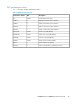


DescriptionUnit
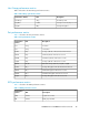
Performance
metrics
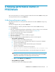
For an XP disk array, Max% indicates the maximum CPU
utilization on PCB [%].
For a P9000 disk array, Max% indicates the maximum
processor utilization on an MP blade. In Figure 21 the Max%
indicates the utilization of MP0.
%Max%
For an XP disk array, Avg% indicates the average CPU util-
ization on PCB [%].
For a P9000 disk array, Avg% indicates the average
utilization of all MPs. In Figure 21 the Avg% indicates the
utilization of MP0, MP1, MP2, and MP3.
%Avg%
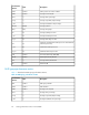
For an XP disk array, MP0 is the CHA PCB Busy Time for
CPU 0 (if installed).
For a P9000 disk array, MP0 is the MP busy time for CPU
0 (if installed).
numberMP0
For an XP disk array, MP1 is the CHA PCB Busy Time for
CPU 1 (if installed).
For a P9000 disk array, MP1 is the MP busy time for CPU
1 (if installed).
numberMP1
For an XP disk array, MP2 is the CHA PCB Busy Time for
CPU 2 (if installed).
For a P9000 disk array, MP1 is the MP busy time for CPU
2 (if installed).
numberMP2
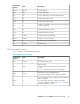
For an XP disk array, MP3 is the CHA PCB Busy Time for
CPU 3 (if installed).
For a P9000 disk array, MP3 is the MP busy time for CPU
3 (if installed).
numberMP3
For an XP disk array, MP4 is the CHA PCB Busy Time for
CPU 4 (if installed).
numberMP4
For an XP disk array, MP5 is the CHA PCB Busy Time for
CPU 5 (if installed).
numberMP5
For an XP disk array, MP6 is the CHA PCB Busy Time for
CPU 6 (if installed).
numberMP6
For an XP disk array, MP7 is the CHA PCB Busy Time for
CPU 7 (if installed).
numberMP7
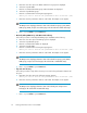
NOTE:
For P9000 disk arrays, MP4 to MP7 will always display a 0 as shown in Figure 21.
Viewing performance metrics in P9000Watch48