
HP XP P9500 Site Preparation Guide (AV400-96609, January 2014)


Four rack configuration (right module)
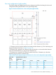
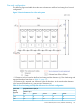
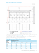
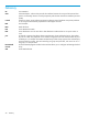
The following figure and table shows the service clearances and floor load rating for a four-rack
configuration (Setting Up DKC-RACK in the right Configuration).
Figure 10 Service clearances for a four rack system (right module)
*1 Clearance (a+b) is based on the floor load rating and the clearance (c). Floor load rating and
required clearances are shown in Table 20 (page 31).
*2 Clearance (d) is required over 300mm to open the front door. In the case that the clearance
(d) is less tan the clearance (a), give priority to clearance (a).
*3 Clearance (e) is required over 200mm to open the rear door. If clearance (e) is less than
clearance (b), give priority to clearance (b).
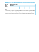
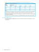
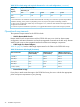
Table 20 Floor load rating and required clearances for a four rack configuration (right module)
Required Clearance (a+b) mFloor Load
Rating
Clearance (c) m
(kg/m2)
C=0.6C=0.6C=0.4C=0.2C=0
00000.1500
000.10.30.5450
0 .10.40.60.81.1400
0.61.01.21.51.8350
Service clearance, floor cutout, and floor load rating 31