
HP XP P9500 Site Preparation Guide (AV400-96609, January 2014)
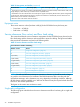
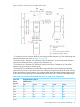
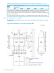
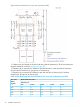
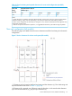
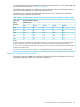
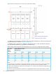

Figure 4 Service clearances for a single rack system
*1 Clearance (a+b) is based on the floor load rating and the clearance (c). Floor load rating and
required clearances are shown in Table 14 (page 23).
*2 Clearance (d) is required over 300mm to open the front door. In the case that the clearance
(d) is less tan the clearance (a), give priority to clearance (a).
*3 Clearance (e) is required over 200mm to open the rear door. If clearance (e) is less than
clearance (b), give priority to clearance (b).
*4 Dimensions in parentheses show allowable range of the front cutout dimensions. Basically,
position the floor cutout in the center of the rack. However, the position may be off center as long
as the cutout allows smooth entrance of an external cable (check the relation between the positions
of the cutout and the opening on the bottom plate of the rack) and is within the allowable range.
Table 14 Floor load rating and required clearances for single rack configuration
Required Clearance (a+b) mFloor Load
Rating
Clearance (c) m
(kg/m2)
C=0.6C=0.6C=0.4C=0.2C=0
00010.500
000.10.10.2450
0.10.10.20.30.3400
0.20.30.40.40.5350
0.40.60.70.80.9300
Notes:
Service clearance, floor cutout, and floor load rating 23