
HP XP P9500 Site Preparation Guide (AV400-96609, January 2014)
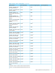
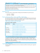
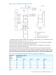
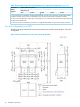
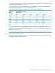
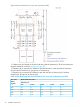
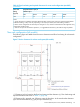
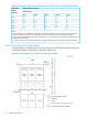
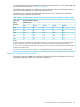
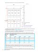

Table 12 Heat, power, and airflow (continued)
Air Flow (M3/min)Power Consumption (kVA)Heat Output (kW)Model Number
3
Actual values at a typical I/O condition. (Random Read and Write, 50 IOPSs for HDD, 2500 IOPSs for SSD, Data
Length: 8Kbytes). These values may increase for future compatible drives.
5
AV411B Base 2.5in Drive Chassis does not include power supplies consequently demands zero (0) kVA and generates
no (0) kW heat. When AV459A/AU DKU Pow supplies are installed in an AV411B/BU, then the chassis fans will
demand same power and heat as AV412B/BU.
6
Maximum values with all fans rotate at maximum.
Equipment noise
The acoustic emission values [loudness in dB (A)] for the P9500 disk array disk array are:
• Front/rear = 65 dB (A)
• Both sides = 65 dB (A)
Service clearance, floor cutout, and floor load rating
This section describes the service clearance requirements for the P9500 disk array, based on the
floor load rating and the clearance and required floor cutouts for cabling. The figures and tables
that provide this information are listed in the following table.
Table 13 Service clearance and floor load ratings
Service Clearance and Floor Load Rating
SectionNumber of racks
“Single rack configuration” (page 22)1
“Two rack configuration (one DKC)” (page 24)2
“Two rack configuration (two DKC)” (page 25)2 (two DKC)
“Three rack configuration (left module)” (page 27)3 (left module)
“Three rack configuration (right module)” (page 28)3 (right module)
“Four rack configuration (left module)” (page 29)4 (left module)
“Four rack configuration (right module)” (page 31)4 (right module)
“Five rack configuration” (page 33)5
“Six rack configuration” (page 34)6
NOTE: For safe and efficient maintenance operations, clearance (c) should be made as large
as possible. Actual clearances for installation should be determined after consulting with the
site/facilities manager, as the clearances can vary, depending on building conditions. Although
all disk chassis come pre-installed, up to 1420 mm of clearance may be required at both front and
back for a disk chassis replacement.
The figures in this section are not drawn to scale.
Single rack configuration
The following figure and table show the service clearances and floor load rating for a single rack
configuration.
22 Installation requirements