HP XP P9500 Site Preparation Guide Abstract This guide describes the site preparation for HP XP P9500 disk arrays. The intended audience is a storage system administrator or authorized service provider with independent knowledge of the HP XP P9500 and Remote Web Console.
© Copyright 2010, 2014 Hewlett-Packard Development Company, L.P. Confidential computer software. Valid license from HP required for possession, use or copying. Consistent with FAR 12.211 and 12.212, Commercial Computer Software, Computer Software Documentation, and Technical Data for Commercial Items are licensed to the U.S. Government under vendor's standard commercial license. The information contained herein is subject to change without notice.
Contents 1 Planning for installation...............................................................................5 Responsibilities.........................................................................................................................5 User responsibilities..............................................................................................................5 HP responsibilities........................................................................................................
Typographic conventions.........................................................................................................38 Glossary....................................................................................................40 Index.........................................................................................................
1 Planning for installation Unless otherwise specified, the term P9000 in this guide refers to the following disk array: • P9500 Disk Array The GUI illustrations in this guide were created using a Windows computer with the Internet Explorer browser. Actual windows may differ depending on the operating system and browser used. GUI contents also vary with licensed program products, storage system models, and firmware versions.
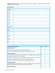
Location: The specific location in the data center (area or “footprint” on the floor) where the P9500 disk array will be installed. User Information Company . Address . Contact . Phone . Mobile . Email . Contact . Phone . Mobile . Email . HP Information 6 Contact . Phone . Mobile . Email . Contact . Phone . Mobile . Email . Notes . . . Installation Planning Checklist Yes No Safety Requirements . .
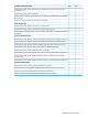
Installation Planning Checklist Yes No Does the data center provide appropriate fire protection for computer equipment such as P9500 disk arrays? . . Does the data center have a raised floor? . . Does the location meet the requirements for service clearance and cable routing (for example, . floor cutouts)? . Does the location meet the floor load rating requirements? . . Power Requirements . . Does the data center meet the AC input power requirements? . .
2 Safety requirements General safety guidelines Observe the following general site guidelines: • General Requirements: The data center must comply with all applicable safety regulations, standards, and requirements for installing and operating industrial computer equipment similar to a P9500 disk array. • Fire protection: The data center must have an operational fire protection system appropriate for use with computer and electrical equipment.
and ramps to a raised computer room floor. Move the cabinet slowly and deliberately, and make sure that the floor is free from foreign objects and cables that the cabinet could roll over. WARNING! To avoid injury, wear protective footwear when moving equipment. Warning about moving parts Even though customers do not install or maintain equipment, these guidelines are provided to prevent possible injury when working with authorized service personnel.
3 Installation requirements Safety requirements Safety requirements and guidelines are covered in “Safety requirements” (page 8). General site requirements The customer site must accommodate the delivery and movement of the equipment from the receiving dock to the installation location in the data center. Equipment clearances Receiving area: The receiving dock, storage area, and receiving area must be large enough to allow movement of and access to crated or packed equipment.
Equipment weight The floors, elevators, and ramps must be able to support the weight of the delivered equipment as it is moved to the installation location. Spreader plates may be required to distribute the load and protect the floor as the equipment is moved from the receiving area to the installation location. Consult the system bill of materials to establish the anticipated summary weights. The weight of the equipment depends on the disk array configuration.
Table 5 Data communication requirements (continued) Column Head Column Head infrastructure, including your choice of router configurations, a supported CMS management server, and access to SMTP server (optional) and DNS servers, in order to support reliable file transfer and serve the overall objectives of the remote support solution. An HP representative will configure C-Track , see “C-Track” (page 12) or contact your HP representative. A twisted pair (Cat 5) cable.
Table 6 P9500 disk array remote support products (continued) HP Product Description Application new P9500 installations, to ensure the optimal support model and highest TCE. AE242A HP XP/P9500 no Remote Device Access Support For customers that commit to utilize Internet and Insight Remote Support connectivity for P9500 Remote Device Monitoring but will not allow for Remote Device Access to the P9500 array from HP for proactive and critical support processes.
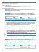
Mechanical specifications The following table lists the mechanical specifications of the P9500 disk array. Table 7 P9500 mechanical specifications Dimension One Rack Two Racks Three Racks Four Racks Five Racks Six Racks Width 24.0 inches 47.6 inches 71.3 inches 95 inches 118.
NOTE: Each Rack is 600mm wide without side covers. Add 5mm to each end of entire assembly for each side cover. Figure 2 Example P9500 disk array configurations Electrical specifications “System heat and power specifications” (page 15) and “System components heat and power specifications ” (page 15) list the heat and power specifications for the P9500 disk array and components. Table 8 System heat and power specifications DKC Module-1 DKU Rack Full Array (DKC-0 plus DKC-1 plus DKU x4) Max Power 5.
Table 9 System components heat and power specifications (continued) Component Product Number HP XP P9500 Disk Array Component Power Consumption Heat Output (kW)1 (kVA)1 AV411B Base 2.5in Drive Chassis see note 5 see note 5 AV412B Complete 2.5in Drive Chassis 0.57 0.600 AV413A Drive Chassis SAS Switch Kit 0.120 0.103 AV423A, AV423B 8-port 2-8 Gbps FC CHA 0.072 0.076 AV424A, AV424B 16-port 2-8 Gbps FC CHA 0.072 0.076 AV425A 16p 1-4 Gbps SW FICON CHA 0.118 0.
Table 9 System components heat and power specifications (continued) Power Consumption Heat Output (kW)1 (kVA)1 Component Product Number HP XP P9500 Disk Array Component 2 Power is consumed during the battery back-up time only. 3 Actual values at a typical I/O condition. (Random Read and Write, 50 IOPSs for HDD, 2500 IOPSs for SSD, Data Length: 8 KB). These values may increase for future compatible drives. 4 Maximum values with all fans rotate at maximum. 5 AV411B Base 2.
Table 10 P9500 AC PDU Options (continued) Product Number Local Power Branch circuit Number of requirements PDU per Rack1 per PDU Plug Type Facility receptacle needed Notes Distribution System AV405A AV405AU 3 phase (5 wire) 2 380-415V, 3Ø, 5-wire, 16A IEC60309 4 pole, 5-wire 380-415VAC, 16A IEC60309 4 pole, 5-wire, 380-415 VAC, 16A For customers with 380 - 415 VAC, Three-Phase, 5-Wire Wye Power Distribution System AV406A AV406AU single phase NEMA 4 200-240V, 1Ø, NEMA L6-30P NEMA L6-30R For c
Environmental specifications Table 11 (page 19)provides the environmental specifications and requirements for the P9500 disk array. Table 11 P9500 environmental specifications Item Operating Not Operating In Storage Temperature 60.8 - 80.9 ºF -18 - 109.4 ºF / (-10 to 43 ºC) -45 - 140ºF (16 to 32 ºC) -18 - 95 ºF / (-10 to 35 ºC)8 (-25 to 60 ºC) Relative Humidity 20 to 80 %2 8 to 90 % 2 5 to 95 % Max. Wet Bulb 78.8 ºF (26ºC) 80.6 ºF (27 ºC) 84.
Table 12 Heat, power, and airflow 20 Model Number Heat Output (kW) Power Consumption (kVA) Air Flow (M3/min) AV375A HP XP P9500 Flash Module Chassis 0.6006 0.6406 - AV392A HP XP P9500 1.6TB 0.0173 Flash Module 0.0183 - AV393A HP XP P9500 3.2TB 0.0173 Flash Module 0.0183 - AV400A - HP P9500 Disk Array DKC Module-0 Rack 1.881 1.971 25 AV400B - HP P9500 Disk Array DKC Module-0 Rack 0.86 0.90 - AV401A - HP P9500 DKC Module-1 Rack 1.831 1.931 25 AV401B - HP P9500 DKC Module-1 Rack 0.
Table 12 Heat, power, and airflow (continued) Model Number Heat Output (kW) Power Consumption (kVA) Air Flow (M3/min) AV443A - HP P9500 2nd SVP High Reliability Kit 0.052 0.055 - AV444A - HP P9500 Cache Memory Adapter 0.068 0.072 - AV447A, AV447B - HP 0.019 P9500 16GB Cache Memory Module 0.020 - AV448A, AV448B - HP 0.019 P9500 32GB Cache Memory Module 0.020 - AV451A - HP P9500 64GB Cache Backup Memory Module 0.0052 0.0052 - AV452A - HP P9500 128GB Cache Backup Memory Module 0.0052 0.
Table 12 Heat, power, and airflow (continued) Model Number Heat Output (kW) Power Consumption (kVA) Air Flow (M3/min) 3 Actual values at a typical I/O condition. (Random Read and Write, 50 IOPSs for HDD, 2500 IOPSs for SSD, Data Length: 8Kbytes). These values may increase for future compatible drives. 5 AV411B Base 2.5in Drive Chassis does not include power supplies consequently demands zero (0) kVA and generates no (0) kW heat.
Figure 4 Service clearances for a single rack system *1 Clearance (a+b) is based on the floor load rating and the clearance (c). Floor load rating and required clearances are shown in Table 14 (page 23). *2 Clearance (d) is required over 300mm to open the front door. In the case that the clearance (d) is less tan the clearance (a), give priority to clearance (a). *3 Clearance (e) is required over 200mm to open the rear door. If clearance (e) is less than clearance (b), give priority to clearance (b).
Table 14 Floor load rating and required clearances for single rack configuration (continued) Floor Load Required Clearance (a+b) m Rating Clearance (c) m (kg/m2) C=0 C=0.2 C=0.4 C=0.6 C=0.6 1. Actual clearances for installation should be determined after consulting with construction specialist responsible for installation building, as they could vary depending on the size/layout of the system and building conditions. 2.
*1 Clearance (a+b) is based on the floor load rating and the clearance (c). Floor load rating and required clearances are shown in Table 15 (page 25). *2 Clearance (d) is required over 300mm to open the front door. In the case that the clearance (d) is less tan the clearance (a), give priority to clearance (a). Table 15 Floor load rating and required clearances for two rack configuration Floor Load Required Clearance (a+b) m Rating Clearance (c) m (kg/m2) C=0 C=0.2 C=0.4 C=0.6 C=0.6 500 0.
Figure 6 Service clearances for a two rack system (two DKC) *1 Clearance (a+b) is based on the floor load rating and the clearance (c). Floor load rating and required clearances are shown in Table 16 (page 26). *2 Clearance (d) is required over 300mm to open the front door. In the case that the clearance (d) is less tan the clearance (a), give priority to clearance (a). *3 Clearance (e) is required over 200mm to open the rear door.
Table 16 Floor load rating and required clearances for a two rack configuration (two DKC) (continued) Floor Load Required Clearance (a+b) m Rating Clearance (c) m (kg/m2) 300 C=0 C=0.2 C=0.4 C=0.6 C=0.6 1.5 1.3 1.2 1.0 0.8 Notes: 1. Actual clearances for installation should be determined after consulting with construction specialist responsible for installation building, as they could vary depending on the size/layout of the system and building conditions. 2.
Table 17 Floor load rating and required clearances for a three rack configuration (left module) Floor Load Required Clearance (a+b) m Rating Clearance (c) m (kg/m2) C=0 C=0.2 C=0.4 C=0.6 C=0.6 500 0.1 0 0 0 0 450 0.4 0.2 0.1 0 0 400 0.8 0.6 0.4 0.3 0 350 1.3 1.1 0.9 0.7 0.4 300 2.3 1.9 1.7 1.5 1.1 Notes: 1.
*1 Clearance (a+b) is based on the floor load rating and the clearance (c). Floor load rating and required clearances are shown in Table 18 (page 29). *2 Clearance (d) is required over 300mm to open the front door. In the case that the clearance (d) is less tan the clearance (a), give priority to clearance (a). *3 Clearance (e) is required over 200mm to open the rear door. If clearance (e) is less than clearance (b), give priority to clearance (b).
Figure 9 Service clearances for a four rack system (left module) *1 Clearance (a+b) is based on the floor load rating and the clearance (c). Floor load rating and required clearances are shown in Table 19 (page 30). *2 Clearance (d) is required over 300mm to open the front door. In the case that the clearance (d) is less tan the clearance (a), give priority to clearance (a).
Four rack configuration (right module) The following figure and table shows the service clearances and floor load rating for a four-rack configuration (Setting Up DKC-RACK in the right Configuration). Figure 10 Service clearances for a four rack system (right module) *1 Clearance (a+b) is based on the floor load rating and the clearance (c). Floor load rating and required clearances are shown in Table 20 (page 31). *2 Clearance (d) is required over 300mm to open the front door.
Table 20 Floor load rating and required clearances for a four rack configuration (right module) (continued) Floor Load Required Clearance (a+b) m Rating Clearance (c) m (kg/m2) 300 C=0 C=0.2 C=0.4 C=0.6 C=0.6 3.0 2.6 2.3 2.0 1.5 Notes: 1. Actual clearances for installation should be determined after consulting with construction specialist responsible for installation building, as they could vary depending on the size/layout of the system and building conditions. 2.
Five rack configuration This following figure and table shows the service clearances and floor load rating for a five-rack configuration. Figure 11 Service clearances for a five rack system *1 Clearance (a+b) is based on the floor load rating and the clearance (c). Floor load rating and required clearances are shown in Table 21 (page 33). *2 Clearance (d) is required over 300mm to open the front door. In the case that the clearance (d) is less tan the clearance (a), give priority to clearance (a).
Table 21 Floor load rating and required clearances for a five rack configuration (continued) Floor Load Required Clearance (a+b) m Rating Clearance (c) m (kg/m2) C=0 C=0.2 C=0.4 C=0.6 C=0.6 400 1.3 1.0 0.7 0.4 0 .1 350 2.2 1.8 1.5 1.2 0.7 300 3.7 3.2 2.8 2.4 1.8 Notes: 1.
Figure 12 Service clearances for a six rack system *1 Clearance (a+b) is based on the floor load rating and the clearance (c). Floor load rating and required clearances are shown in Table 22 (page 35). *2 Clearance (d) is required over 300mm to open the front door. In the case that the clearance (d) is less tan the clearance (a), give priority to clearance (a).
Table 22 Floor load rating and required clearances for a six rack configuration (continued) Floor Load Required Clearance (a+b) m Rating Clearance (c) m (kg/m2) 300 C=0 C=0.2 C=0.4 C=0.6 C=0.6 4.4 3.8 3.3 2.9 2.1 Notes: 1. Actual clearances for installation should be determined after consulting with construction specialist responsible for installation building, as they could vary depending on the size/layout of the system and building conditions. 2.
4 Support and other resources Contacting HP For worldwide technical support information, see the HP support website: http://www.hp.
Conventions for storage capacity values P9000 disk arrays use the following values to calculate physical storage capacity values (hard disk drives): • 1 KB (kilobyte) = 1,000 bytes • 1 MB (megabyte) = 1,0002 bytes • 1 GB (gigabyte) = 1,0003 bytes • 1 TB (terabyte) = 1,0004 bytes • 1 PB (petabyte) = 1,0005 bytes • 1 EB (exabyte) = 1,0006 bytes P9000 disk arrays use the following values to calculate logical storage capacity values (logical devices): • 1 KB (kilobyte) = 1,024 bytes • 1 MB (megab
CAUTION: IMPORTANT: NOTE: TIP: Indicates that failure to follow directions could result in damage to equipment or data. Provides clarifying information or specific instructions. Provides additional information. Provides helpful hints and shortcuts.
Glossary CB Circuit Breaker. CHA Channel adapter. A device that provides the interface between the array and the external host system. Occasionally, this term is used synonymously with the term channel host interface processor (CHIP). C-Track Continuous Track. An HP software program that detects internal hardware component problems on an array and automatically reports them to HP Support Services. DKC Disk controller. HDD Hard disk drive. PDP Power Distribution Panels.
Index C checklist, 5 clearances, equipment, 10 contacting HP, 37 conventions document, 38 storage capacity values, 38 text symbols, 38 D disk arrays supported models, 5 document conventions, 38 documentation HP website, 37 providing feedback, 37 E equipment clearances, 10 equipment weight, 11 G guidelines access by authorized personnel, 8 cabling, 8 earthquake safety, 8 electrical safety, 9 equipment modifications, 8 fire protection, 8 hazards, 8 loose clothing, 8 moving equipment, 8 operating in storms,