HP StorageWorks P9000 Mainframe Host Attachment and Operations Guide P9500 Disk Array Abstract This guide provides requirements and procedures for connecting a P9000 disk array to a mainframe host system, and for configuring the disk array for use with the mainframe operating system. This document is intended for system administrators, HP representatives, and authorized service providers who are involved in installing, configuring, and operating the HP P9000 storage systems.
© Copyright 2010, 2011 Hewlett-Packard Development Company, L.P. Confidential computer software. Valid license from HP required for possession, use or copying. Consistent with FAR 12.211 and 12.212, Commercial Computer Software, Computer Software Documentation, and Technical Data for Commercial Items are licensed to the U.S. Government under vendor's standard commercial license. The information contained herein is subject to change without notice.
Contents 1 Overview of mainframe operations...............................................................5 Mainframe compatibility and functionality...................................................................................5 Connectivity.............................................................................................................................5 Program products for mainframe.................................................................................................
Setting up storage units for zSeries hosts running Linux............................................................34 Setting up a Linux system to use FCP protocol devices on zSeries hosts......................................35 Adding permanent devices for zSeries hosts running Linux.......................................................36 5 Troubleshooting........................................................................................38 Troubleshooting............................................
1 Overview of mainframe operations This chapter provides an overview of mainframe host attachment issues, functions, and operations.
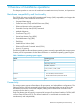
The FICON/zHPF and fibre-channel CHA features are available in shortwave (multimode) and longwave (single-mode) versions. • FICON/zHPF: The same FICON CHAs are used for FICON and FICON/zHPF. The FICON CHAs provide data transfer speeds of up to 800 MB/sec (8 Gbps) and have 16 ports per feature (pair of boards). The CHPID must be set as the FC type in the hardware configuration definition.
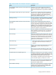
Table 2 Remote Web Console-based software for mainframe users Name Description HP StorageWorks P9000 Continuous Access Synchronous Enables the user to perform remote copy operations for Mainframe between storage systems in different locations. Provides synchronous and asynchronous copy modes for mainframe data. HP StorageWorks P9000 Business Copy for Mainframe Allows the user to create internal copies of volumes for purposes such as application testing and offline backup.
Table 3 Host/Server-Based Software for Mainframe Users 8 Name Description Business Continuity Manager Provides control and monitoring of mainframe-based replication products that support automation of application testing, scheduled site switching activities, and disaster recovery for business continuance. Data Exchange Enables users to transfer data between mainframe and open-system platforms using the FICON channels, for high-speed data transfer without requiring network communication links or tape.
2 FICON/zHPF host attachment This chapter describes and provides general instructions for attaching the storage system to a mainframe host using a FICON/zHPF CHA. For details on FICON/zHPF connectivity, FICON/Open intermix configurations, and supported HBAs, switches, and directors, contact your HP representative. FICON/zHPF for zSeries hosts This section describes some things you should consider before you configure your system with FICON/zHPF adapters for zSeries hosts.
Table 4 FICON/zHPF physical specifications (continued) Item Cable FICON/zHPF Single Mode/9um Multi Mode/50 or 62.5um Distance Long wave Single Mode/9um 10 km, 20 km (with RPQ) Short wave Multi Mode/ 62.
Table 6 Operating environment required for FICON/zHPF Items CPU Specification z9, z10, zEnterprise FICON Express FICON Express2 FICON Express4 FICON Express8 (not supported by z9) z900 Native FICON FICON Express z990 FICON Express G5/G6 Native FICON z800, zSeries Operating system OS/390 Rev. 2.6 and later released For FICON: Z-OS R1.V1 and later released For FICON/zHPF: z/OS V1.7 with the IBM Lifecycle Extension for z/OS V1.7 (5637-A01) z/OS V1.8, V1.9 with PTFs z10, zEnterprise VM/ESA 2.4.
Figure 3 zHPF protocol read/write sequence Hardware specifications For details on FICON/zHPF connectivity, FICON/Open intermix configurations, and supported HBAs, switches, and directors for the storage array, contact your HP representative. FICON CHAs The CHAs contain the microprocessors that process the channel commands from the host(s) and manage host access to cache.
Figure 4 Mainframe Logical Paths (Example 1) Figure 5 Mainframe logical paths (example 2) The FICON /zHPF CHAs provide logical path bindings that map user-defined FICON/zHPF logical paths. Specifically: • Each CU port can access 255 CU images (all CU images of logical storage system). • To the CU port, each logical host path (LPn) connected to the CU port is defined as a channel image number and a channel port address.
Figure 6 FICON/zHPF channel adapter support for logical paths (example 1) The following figure shows another example of logical paths. Instead of being controlled by physical ports, LPns on the storage system are controlled by CU images. Separating LPns from hardware provides flexibility that allows CU ports to share logical path resources as needed. Specifically: • Maximum number of LPn/CU images per storage system is 2048. • Maximum number of CU images per storage system is 64.
Figure 8 Example of a point-to-point topology Switched point-to-point topology A FICON channel in FICON native mode connects one or more processor images to a Fibre Channel link, which connects to a Fibre Channel switch, and then dynamically to one or more FC switch ports (internally within the switch). From the switch ports, another Fibre Channel link to FICON CU ports interconnects with one or more control units and/or images (logical control units).
Figure 9 Example of a switched point-to-point topology Cascaded FICON topology A FICON channel in FICON native (FC) mode connects one or more processor images to a Fibre Channel link, which connects to a Fibre Channel switch, and then dynamically through one or more FC switch ports (internally within the switch) to a second FC switch in a remote site via FC link(s).
In a Cascaded FICON topology, one Fibre Channel link is attached to the FICON channel. From the switch, the FICON channel communicates with a number of FICON CUs on different switch ports. At the control unit, the control unit and device-addressing capability is the same as the point-to-point topology.
Figure 12 Required high-integrity features for cascaded topologies Physical host connection specifications The following table lists the physical specifications associated with host connections.
Figure 13 Logical host connections (FICON/zHPF) Enabling for Compatible High Perf FICON connectivity software (zHPF) operations Activating the zHPF program product The zHPF PP license is required to activate zHPF on the storage system.
To install the zHPF function in cascading switch configurations, perform either Option (1) or Option (2): • Option (1): Vary the channel path in the switch cascading configuration used for zHPF offline with the CF CHP(Channel path 1-Channel path n),OFFLINE command, and then vary it online with the CF CHP(Channel path 1-Channel path n),ONLINE command. If you always keep the alternate path in the same path group when placing the channel path offline, you can enable zHPF without stopping host access.
3 Mainframe operations This chapter discusses the operations available for mainframe hosts. Mainframe configuration The first step in configuring the storage system is to define the storage system to the mainframe host(s).
defines a CU image by its control unit address, which can be 00 to FE for FICON/zHPF connectivity. FICON/zHPF connectivity can be used with CU types 2105 (2105-F20 or later) and 2107. CAUTION: The following are cautions when using IOCP or HCD: • When multiple LPARs/mainframes can access the volumes, use FEATURE=SHARE for the devices. • Up to 16,384 addresses per physical interface are allowed by MVS with FICON/zHPF channels.
The following HCD steps correspond to the 2105 IOCP definition shown in the previous example. IMPORTANT: The HCD PAV definitions must match the configurations in the storage system. If not, error messages are issued when the Hosts are IPL'd or the devices are varied online. 1. From an ISPF/PDF primary options menu, select the HCD option to display the basic HCD panel. On this panel you must verify the name of the IODF or IODF.WORK I/O definition file to be used. San Diego OS/390 R2.
| F1=Help F2=Split F3=Exit F9=Swap F12=Cancel | '-----------------------------------------------------------------------' 4. On the Control Unit List panel, if a 2105 type of control unit already exists, then an “Add like” operation can be used by inputting an A next to the 2105 type control unit and pressing Enter. Otherwise, press F11 to add a new control unit.
| | | F1=Help F2=Split F3=Exit F4=Prompt F5=Reset | | F6=Previous F7=Backward F8=Forward F9=Swap F12=Cancel | '-----------------------------------------------------------------------------' | F6=Previous F7=Backward F8=Forward F9=Swap F12=Cancel | '-----------------------------------------------------------------------------' 7.
10. On the I/O Device List panel, press F11 to add new devices. Goto Filter Backup Query Help -------------------------------------------------------------------------I/O Device List Command ===> ___________________________________________ Scroll ===> PAGE Select one or more devices, then press Enter. Control unit number : 8000 To add, use F11. Control unit type .
| | | Specify or revise the following values. | | | | Device number . : 8000 Number of devices . . . . : 128 | | Device type . . : 3390B | | Processor ID . . : PROD | | | | Unit address . . . . . . . . . . 00 + (Only necessary when different from | | the last 2 digits of device number) | | Time-Out . . . . . . . . . . . . No (Yes or No) | | STADET . . . . . . . . . . . . . Yes (Yes or No) | | | | Preferred CHPID . . . . . . . . __ + | | Explicit device candidate list .
| LOCANY No UCB can reside in 31 bit storage | | WLMPAV Yes Device supports work load manager | | SHARED Yes Device shared with other systems | | SHAREDUP No Shared when system physically partitioned | | ***************************** Bottom of data ****************************** | | | | | | F1=Help F2=Split F3=Exit F4=Prompt F5=Reset | | F7=Backward F8=Forward F9=Swap F12=Cancel | '-----------------------------------------------------------------------------' 17.
OWNERID(ZZZZZZZ) /* XXXX = physical install address, YYYYYY = new volume ID, ZZZZZZZ = volume ID owner. Device operations: ICKDSF The storage system supports the ICKDSF media maintenance utility. The ICKDSF utility can also be used to perform service functions, error detection, and media maintenance. Because the P9000 disk array is a RAID device, there are only a few differences in operation from conventional DASD or other RAID devices.
Table 10 ICKDSF Commands for P9000 Disk Array Contrasted to RAMAC (continued) Command REVAL Argument REFRESH DATA, NODATA CONTROL INIT REFORMAT CPVOLUME Storage System Return Code P9000 disk array CC = 0 RAMAC CC = 12 Device not supported for the specified function. P9000 disk array CC = 12, F/M = 04 (EC=66BB) Error, not a data check. Processing terminated. RAMAC CC = 0, Data/Nodata parameter not allowed. P9000 disk array CC=0 RAMAC CC = 0, ALT information not displayed.
LISTDATA LISTDATA /* • COUNTS COUNTS VOLUME(VOL128) VOLUME(VOL192) UNIT(3390) UNIT(3390) SUBSYSTEM SUBSYSTEM Subsystem counter reports. The cache statistics reflect the logical caching status of the volumes. For the storage system, HP recommends that you set the nonvolatile storage (NVS) ON and the DASD fast write (DFW) ON for all logical volumes. This will not affect the way the storage system caches data for the logical volumes.
zVM (VM/ESA) Cache operations When the storage system is managed under VM/ESA, the following SET CACHE commands are effective across multiple SSIDs: • SET CACHE SUBSYSTEM ON|OFF • SET NVS SUBSYSTEM ON|OFF • SET CACHEFW SUBSYSTEM ON|OFF • DESTAGE SUBSYSTEM zVSE (VSE/ESA) Cache operations When using VSE/ESA to manage the storage system, the following CACHE commands are effective across multiple SSIDs: • CACHE SUBSYS=cuu,ON|OFF|STATUS • CACHE SUBSYS=cuu,FAST,ON|OFF • CACHE SUBSYS=cuu,NVS,ON|OFF •
4 Linux operations This chapter describes storage system operations in a Linux host environment. Overview of zLinux operations The storage system supports attachment to the following mainframe Linux operating systems: • Red Hat Linux for S/390 and zSeries • SuSE Linux Enterprise Server for IBM zSeries For information on supported versions, Linux kernel levels, and other details, contact your HP representative.
Linux for S/390 (31-bit) Linux for S/390 is a 31-bit version of Linux. It also runs on zSeries models in 31-bit mode. The 31-bit limitation limits the addressable main storage to 2 GB. Linux for zSeries (64-bit) Linux on zSeries supports the 64-bit architecture on all zSeries models. The 64-bit support eliminates the 31-bit storage limitation of 2 GB. FCP support Linux for zSeries can access FCP and FICON/zHPF controllers and devices with the appropriate I/O driver support.
3. From the General host information panel, complete the following fields for each Fibre Channel host adapter: • Host type • Nickname • Description When you are finished, click OK. 4. 5. 6. 7. From the Define host ports panel, specify the host ports for this host. Click Add to add each host port to the defined host ports table. From the Define host WWPN panel, specify the worldwide port names for the selected hosts. When finished, click Next.
• zfcp: provides FCP support for zSeries Linux • sd_mod: SCSI disk support1 Load the modules in the order shown. Use the modprobe command to load all modules. Except for the zfcp module, you can load all modules without parameters. The zfcp module requires parameters to map the FCP devices on the storage unit.
4. • Create as many logical volumes as you need using the following command: lvcreate --size 16G fcpvg • Enable the alternate paths to the physical volumes using the pvpath command: pvpath --path0 --enable y /dev/sda1 pvpath --path1 --enable y /dev/sda1. If both paths are set to a weight of 0, they will load balance. These configurations yield the SCSI device /dev/sda - /dev/sdc, This device is accessible on the first path and the SCSI device /dev/sdd - /dev/sdf accessed on the second path.
5 Troubleshooting This chapter provides error codes, troubleshooting guidelines and customer support contact information. Troubleshooting For troubleshooting information on the storage system, see the HP StorageWorks P9000 Owner Guide. For troubleshooting information on Remote Web Console, see the HP StorageWorks P9000 Remote Web Console User Guide .. If you are unable to resolve an error condition, contact your HP support representative.
6 Support and Other Resources Contacting HP For worldwide technical support information, see the HP support website: http://www.hp.
• 1 GB (gigabyte) = 1,0003 bytes • 1 TB (terabyte) = 1,0004 bytes • 1 PB (petabyte) = 1,0005 bytes • 1 EB (exabyte) = 10006 bytes HP P9000 storage systems use the following values to calculate logical storage capacity values (logical devices): • 1 block = 512 bytes • 1 KB (kilobyte) = 1,024 (210) bytes • 1 MB (megabyte) = 1,0242 bytes • 1 GB (gigabyte) = 1,0243 bytes • 1 TB (terabyte) = 1,0244 bytes • 1 PB (petabyte) = 1,0245 bytes • 1 EB (exabyte) = 10246 bytes HP product documentatio
Glossary AL-PA Arbitrated loop physical address. CHA Channel Adapters. CHPID Channel path ID. command device A volume on the disk array that accepts HP StorageWorks Continuous Access or HP StorageWorks Business Copy control operations which are then executed by the array. CU Control Unit. Contains LDEVs and is approximately equivalent to SCSI Target ID. CVS Custom volume size.
PA Physical address. path A path is created by associating a port, a target, and a LUN ID with one or more LDEVs. Also known as a LUN. PiT Point-in-time. port A physical connection that allows data to pass between a host and a disk array. PP Program product. R-SIM Remote service information message. RAMAC IBM computer with moving head hard disk. RSCN Registered state-change notification. SAN Storage area network. A network of storage devices available to one or more servers.
Index A algorithms dynamic cache mgmt, 30 alias address range, 22 C wlmpav, 27 R related documentation, 39 reports erep sim, 32 cache loading mode, 31 statistics, 30 commands cache, 32 idcams setcache, 31 listdata, 30 listdata status, 31 contacting HP, 39 conventions storage capacity values, 39 conversion fba to ckd, 5 copy functions dasd on RAID, 8 S D U data sequential access pattern , 31 data transfer max speed, 6 document related documentation, 39 documentation HP website, 39 providing feedback,