
HP XC System Software Hardware Preparation Guide Version 4.0

instructed to perform the task just after the discover command discovers the IP addresses of
the console ports.
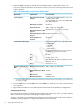
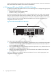
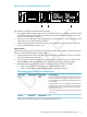
Figure 4-13 shows a rear view of the HP ProLiant DL165 G5 server and the appropriate port
assignments for an HP XC system.
Figure 4-13 HP ProLiant DL165 G5 Server Rear View
3 1 2
The callouts in the figure enumerate the following:
1. This port is used for the connection to the Administration Switch (branch or root). On the
rear of the node, this port is marked as NIC1.
2. If a Gigabit Ethernet (GigE) interconnect is configured, this port is used for the interconnect
connection. Otherwise, it is used for an external connection. On the rear of the node, this
port is marked as NIC2.
3. The port labeled LO100i is used for the connection to the Console Switch.
Setup Procedure
Perform the following procedure for each HP ProLiant DL165 G5 node in the HP XC system.
Change only the values that are described in this procedure; do not change any factory-set values
unless you are instructed to do so.
1. Use the instructions in the accompanying hardware documentation to connect a monitor,
mouse, and keyboard to the node.
2. Turn on power to the node. Watch the screen carefully during the power-on self-test, and
press the F10 key when prompted to access the BIOS Setup Utility. You configure the
Lights-Out 100i (LO-100i) console management device using this utility.
The BIOS Setup Utility displays the following information about the node:
BIOS ROM ID:
BIOS Version:
BIOS Build Date:
Record this information for future reference.
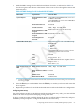
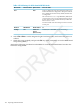
3. Make the following BIOS settings as provided in Table 4-23.
Table 4-23 BIOS Settings for HP ProLiant DL165 G5 Nodes
Set to This ValueOption NameSubmenu NameMenu Name
Disabled
Bootup Num-LockBoot Settings ConfigurationMain
3F8
Embedded Serial Port IRQ:I/O Device ConfigurationAdvanced
IRQ 4
Interrupt:
S-ATA
S-ATA ModeS-ATA Configuration
Enabled
INT13 support
IRQ [3F8h,4]
Base AddressRemote Access
Configuration
115200 8,n,1
Serial Port Mode
4.7 Preparing the Hardware for CP4000 (AMD Opteron) Systems 91