
HP XC System Software Hardware Preparation Guide Version 4.0
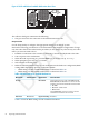
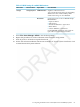
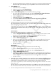

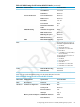
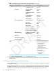

Figure 4-12 HP ProLiant DL145 G3 Server Rear View
3 1 2
The callouts in the figure enumerate the following:
1. This port is used for the connection to the Administration Switch (branch or root). On the
rear of the node, this port is marked as NIC1.
2. If a Gigabit Ethernet (GigE) interconnect is configured, this port is used for the interconnect
connection. Otherwise, it is used for an external connection. On the rear of the node, this
port is marked as NIC2.
3. The port labeled LO100i is used for the connection to the Console Switch.
Setup Procedure
Perform the following procedure for each HP ProLiant DL145 G2 and DL145 G3 node in the HP
XC system. Change only the values that are described in this procedure; do not change any
factory-set values unless you are instructed to do so.
1. Use the instructions in the accompanying hardware documentation to connect a monitor,
mouse, and keyboard to the node.
2. Turn on power to the node. Watch the screen carefully during the power-on self-test, and
press the F10 key when prompted to access the BIOS Setup Utility. You configure the
Lights-Out 100i (LO-100i) console management device using this utility.
The BIOS Setup Utility displays the following information about the node:
BIOS ROM ID:
BIOS Version:
BIOS Build Date:
Record this information for future reference.
3. Table 4-21 provides the BIOS settings for ProLiant DL145 G2 nodes.•
• provides the BIOS settings for ProLiant DL145 G3 nodes.
Table 4-21 BIOS Settings for HP ProLiant DL145 G2 Nodes
Set to This ValueOption NameSubmenu NameMenu Name
Off
NumlockBoot OptionsMain
Disabled
MCFG TableAdvanced
Dedicated NIC
NIC Option
Enabled
Disable Jitter bitHammer Configuration
Disabled
page Directory Cache
Enabled
DevicePCI Configuration/Ethernet
On Board (for Ethernet 1 and
2)
Enabled
Option ROM Scan
40h
Latency timer
BMC COM Port
Serial PortI/O Device Configuration
88 Preparing Individual Nodes